Heat Transfer Analysis for Endothermic Reacting Fluids
Hiroyuki Kimura
*Division of Production and Information Systems Engineering, Muroran Institute of Technology 27-1, Mizumoto, Muroran, Hokkaido 050-8585, Japan
[email protected]
Keywords: Endothermic Fuels, Regenerative Cooling, Convective Heat Transfer Abstract
Endothermic fuels are known as a probable fuel for hypersonic atmospheric flight vehicles and advanced propulsion systems, as well as cryogenic fuels.
Especially, from the standpoint of the advanced regenerative cooling use, they are quite useful as a coolant fuel because of their large heat sink due to their chemical decompositions; so-called endothermic cooling effect. However, no heat transfer equations have been proposed taking into account such endothermic reactive behaviors concretely. This paper describes an analytical method for evaluation of the heat transfer rates between endothermic reacting coolant fuel and coolant-side wall in the regenerative cooling passages. Heat transfer mechanism is indicated based on a classical transport- phenomenological approach. A new relational expression of Nusselt number ratio for forced- convective heat transfer with such endothermic reactions is also proposed by theoretical approaches using some classical hypotheses. Its applicability is assessed provisionally by comparison with confirmed results of heated tube tests for supercritical JP-7 fuel carried out at NASA Lewis Research Center, using its heat sink characteristics evaluated by United Technologies Research Center (UTRC). As a result, it has been suggested that the proposed relational equation is applicable to the evaluation of enhancement of Nusselt numbers due to such reactions in developed turbulent flows such as in the regenerative cooling passages.
Introduction
To achieve the practical use of hypersonic atmospheric flight vehicles and advanced propulsion systems for them, it is necessary to develop effective cooling technologies against some associated thermal issues; e.g. aerodynamic heating on the body surface, high heat load inside the combustion chamber.
Endothermic fuels—storable hydrocarbon fuels, such as JP-7, JP-8+100, methylcyclohexane etc.—are known as a probable fuel for such vehicle systems as well as cryogenic fuels. They can augment their heat sink capabilities due to decompositions of the fuel molecules at high-temperatures generally over 900 K
1)-5).
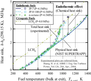
Figure 1 shows some confirmed enhanced total heat sink capabilities of typical hydrocarbon fuels evaluated by Huang et al. at UTRC
6). Physical (i.e.
sensible) heat sink curves, namely without chemical heat sink effects, of the hydrocarbon fuels and cryogenic LCH
4were estimated using NIST SUPERTRAPP
7). Figure 1 indicates also that the enhanced total heat sink capabilities of the hydrocarbon fuels due to their chemical decompositions are comparable to that of the cryogenic LCH
4.
One of the problems, to be solved for a practical use of such endothermic fuels into the advanced regenerative cooling system technologies, is to investigate their heat transfer characteristics enhanced due to their large heat sink effects. However, currently, no heat transfer equations have been proposed taking into account their chemical decomposition behaviors concretely; except experimental correlation methods such as property ratio method, reference temperature method
8)-10), etc. for some particular jet or rocket fuels.
In this paper, an analytical method is proposed for evaluation of the improved heat transfer rates between endothermic reacting coolant fuel and coolant-side wall such as in the regenerative cooling passages for advanced future hypersonic propulsions. Heat transfer mechanisms which involved endothermic reactive behaviors are described based on a classical transport- phenomenological approach. In this theoretical approach, a new state-variable—extent of reaction—is introduced for the description of chemically-related insensible heats. A new rational expression equation of Nusselt number ratio is derived; it denotes the ratio
* Doctoral student.
Fig. 1 Heat sink capabilities of endothermic fuels (JP-7, JP-8+100, and n-octane); comparing to the sensible heat sick capability of cryogenic LCH
4.
5
4
3
2
1
0 Heat sink, h-h0 (298.15 K), MJ/kg
1400 1200 1000 800 600 400 200
Fuel temperature (bulk at exit), Tb,exit, K
Endothemic fuels , JP-7 (P=4.1MPa) , JP-8+100 (P=4.1MPa) , n-octane (P=4.1MPa) Cryogenic Fuels
LCH4 (P=8.0 MPa)
Experimental plots are referred from:
Huang, H. et al, ASME J. Eng. Gas T urbines Power, Vol.126, 284, Apr., 2004.
Total heat sink (experimental)
Physical heat sink (NIST SUPERTRAPP)
Endothermic effect (Chemical heat sink)
LCH4
of heat fluxes (or ratio of heat transfer coefficients) with to without endothermic reactions.
A Theory for Heat Transfer Related to Endothermic Reactions
For the regenerative cooling use of endothermic cooling effect as mentioned above, chemical decompositions are induced due to high heat loads from the high temperature combustor walls. Then, it is considered the reaction which occurs in the coolant passage as heterogeneous reaction; not uniformly- reacting homogeneous reaction. Therefore, hereinafter, the reactions are treated as the former.
Reaction Model: Introduction of the Extent of Reaction
Consider a generalized overall reaction equation for an arbitrary chemical decomposition reaction of mixtures as follows:
∑
∑ →
j j j i
i
i
R
P,P
R,
ν
ν , (1) where, R
iis reactant component, P
iis product component which is decomposed due to advancement of the reaction. Then, ν
R,iand ν
P,jare stoichiometric coefficients of the corresponding reactant and product components respectively. According to Hess’s law, amount of the heat of reaction in Eq. (1) is not depends on its reaction paths or its intermediate products. Particularly, if the reactant is one- component, Eq. (1) can be written as:
∑
→
j j j
P
R
P,R
ν
ν . (1)’
For the chemical reaction as denoted in Eq. (1), the stoichiometric relation expression is defined as:
n n i
i
dN
dN dN
d dN
R, R, R,
R, 2
R, 2 R, 1 R,
1 R,
ν ν
ν ξ ν
= −
− =
=
− =
− =
≡ L L
m m j
j
dN
dN dN dN
P, P, P,
P, P,2
P,2 P,1
P,1
ν ν
ν
ν = = = =
= L L , (2)
where, dN
R,iand dN
P,jare amount of change in number of moles of the corresponding reactants and products, respectively. Then dξ is the amount of change in the extent of reaction for the overall reaction; a state variable for chemically reacting systems defined by de Donder. The extent of reaction dξ represents the amount of changes in number of moles of the all components which participates in the chemical reaction
11).
Due to introduction of the extent of reaction ξ as above, specific enthalpy for chemically reacting fluid is represented as a function of its temperature Τ and ξ, as h = h(T, ξ) in a constant pressure system. Therefore, amount of change in the specific enthalpy of the fluid due to advancement of chemical reaction is proportional to the amount of change in the extent of reaction as dh
chem= h
p,Tdξ. Here, h
p,Tis chemical specific heat, defined as h
p,T≡ (∂h/∂ξ)
p,T11)for a constant pressure and temperature system. It denotes the rate of change in chemical enthalpy—i.e. the heat of reaction—per unit extent of reaction for a constant
pressure and temperature system. As well as physical specific heat c
p,ξ—a rate of change in physical enthalpy per unit temperature—is defined as c
p,ξ≡ (∂h/∂T)
p,ξin a partial differential form for a constant pressure and extent of reaction system. The specific heats h
p,Tand c
p,ξdenote also the enthalpy/energy densities due to their definitions. The extent of reaction ξ denotes a degree of change in insensible chemical heat of reaction; as well as the temperature denotes a degree of sensible physical heat which is measurable by using such as thermometers.
Definition of the Nusselt Number Ratio
According to previously reported results of heated tube tests using some hydrocarbon fuels, e.g. the tests carried out at NASA Lewis Research Center using JP- 7
12)etc., it has been confirmed that the overall heat flux which convected into the fuels from high- temperature wall is enlarged due to their chemical decompositions.
First of all, consider a forced-convective flow along a high-temperature wall as shown in Fig. 2. Here, for the description of the enhanced overall heat flux, increment of heat flux related to the decomposition of the fuels is defined as q
ychem; it is allowed due to the above-mentioned confirmed fact. Then, the overall heat flux q
ytotalis expressed as:
chem total
y
y
q
y
q T +
∂
− ∂
= λ , (3) where, first part of the right-hand-side is the local heat flux convected into the fuels as a thermally-related heat flux q
yphys; it is denoted by the Fourier’s law of heat conduction. Here, λ is molecular thermal conductivity of the fuel, and ∂T/∂y is the temperature gradient in the direction of the heat flow.
Fig. 2 Overall heat fluxes convected into the endothermically-reacting flow along a high- temperature wall.
high-temperature wall q
A
total =
endothermically-reacting flow
y = 0
y qphys
y = 0
y + qchem
y = 0 y
heat flux at the wall surface heat flux at an arbitrary position y
qytotal=qphysy + qychem
A
velocity profile u(y) temperature profile T(y)
u(y)
Tw u
y
A
T(y)
T y
y
x
From the definition of the Nusselt number—the ratio of the convective heat flux at the wall surface to the molecular heat conduction of the fluid—, Nusselt number ratio Nu
*= Nu
total/Nu
physwhich denotes the ratio of convective flows with to without decompositions is described as:
0 phys
0 chem
0 phys
0 total
phys total phys total
*
1
Nu Nu Nu
=
=
=
=
= +
=
=
=
y y y y
y y y y
q q q
q α
α (4)
where, α
totaland α
physare heat transfer coefficients with and without the decompositions respectively.
Here, they are defined as due to the Newton’s law of cooling:
q
ytotal= α
totalΔ T
w, (5) q
yphys= α
physΔ T
w, (6) where, ΔT
wis a temperature difference between the wall temperature T
wand the reference temperature T
refof the fluid. Eq. (4) denotes that the non- dimensionalized Nusselt number Nu
*equals to the ratio of heat transfer coefficients α
totalto α
physas well as to the ratio of heat fluxes at the wall surface q
ytotal|
y=0to q
yphys|
y=0.
A Description of the Enhanced Local Heat Flux due to Endothermic reactions
According to the transition-state theory—or the extremum principle for thermodynamic potentials—, advancement of chemical reaction requires the addition of energy from external energy source, as well as its temperature rise also requires that. In other words, substances at equilibrium in an adiabatic system do not advance the reactions or not raise the temperature by themselves.
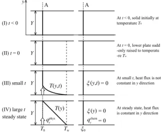
For the description of the enhanced heat flux due to endothermic reaction, here consider a thin slab of solid material of area A located between two parallel plates as shown in Figure 3; based on the description of the Fourier’s law of heat conduction by Bird et al.
13)Here, it is assumed that the upper plate is adiabatic wall.
Figure 3 (a) shows the development process of the profiles of the temperature T and the extent of reaction ξ without any chemical reactions. In this case, due to chemical reactions are not advanced, the extent of reaction profiles is not created; that is, ξ = 0 constantly.
Hence, the heat flux through the slab in this case is described by Fourier’s law of heat conduction; that is, q
ychem= 0 in Eq. (3).
Then, Fig. 3 (b) shows the development process of the profiles of the temperature T and the extent of reaction ξ with endothermic reactions. Imagine that:
(I) Initially, for time t < 0, the slab is at temperature T
0and at extent of reaction ξ
0= 0 throughout.
(II) At t = 0, the lower plate is suddenly brought to a slightly higher temperature T
wand maintained at that temperature constantly. At the same time, the slab temperature at y = 0—the position that the slab molecules contact with the lower plate—is brought to the temperature T
w. Furthermore, if the temperature T
wexceeds the reactive transition-state temperature of the slab molecules, the extent of reaction is also brought
to the extent of reaction ξ
w; an attainable extent of reaction which is determined by the lower plate temperature T
w.
(III) As time proceeds, the profiles of temperature T and extent of reaction ξ in the slab changes. The extent of reaction ξ(y) at an arbitrary y position is also determined by the temperature T(y) at the correspondent position.
(IV) Ultimately, linear steady-state distributions of temperature T(y) and extent of reaction ξ(y) are attained, as shown in Fig. 3 (b).
When this steady-state condition has been reached, constant rates of heat flow Q
yphysand Q
ychemthrough the slab is required to maintain the temperature difference ΔT = T
w–T
0and the extent of reaction distance Δξ = ξ
w–ξ
0. It is found then that for sufficiently small values of ΔT and Δξ, the following relation holds:
Fig. 3 Development processes of the temperature profile and extent of reaction profile for a solid substance between two parallel plates; adiabatic and non-adiabatic walls.
qphys
y qchem
y
A
Tw
T(y) Y
Y Y Y
A
(I) t < 0
(II) t = 0
(III) small t
(IV) large t
T0 ξ0
T(y,t) ξ(y,t)
steady state ξ(y)
= 0
= 0
= 0 At steady state, heat flux is constant in y direction At small t, heat flux is not constant in y direction At t < 0, solid initially at temperature T0
At t = 0, lower plate sudd -enly raised to temperatu -re Tw
y
(a) Profiles without any chemical reactions.
qphys
y qchem
y
A
Tw
T(y) Y
Y Y Y
A
(I) t < 0
(II) t = 0
(III) small t
(IV) large t
T0 ξ0 ξw
T(y,t) ξ(y,t)
ξ(y) steady state
At steady state, heat flux -es are constant in y direc -tion
At small t, heat fluxes are not constant in y direction At t < 0, solid initially at temperature T0 and at ext -ent of reactionξ0
At t = 0, lower plate sudd -enly raised to temperatu -re Tw and to extent of rea -ctionξw
y
(b) Profiles with endothermic reactions.
Y T A
Q
yphys= λ ⋅ Δ , (7)
Y A
Q
ychem= κ ⋅ Δ ξ , (8) that is, the rates of heat flow per unit area A are proportional to the temperature decrease and the extent of reaction decrease over the distance Y. Here, a new constant of proportionality κ is defined as thermal conductivity of the slab related to the advancement of endothermic reactions. The total heat flow through the stab Q
ytotalis sum of the heat flows Q
yphysand Q
ychem. For description of the limiting form of Eq. (7) and (8), it is assumed that the slab thickness approaches zero.
That is, the local rates of heat flow per unit area—
namely, heat fluxes—in the positive y direction are described as:
y q
yT
∂
⋅ ∂
−
= λ
phys
, (9)
q
yy
∂
⋅ ∂
−
= κ ξ
chem
, (10) therefore, the overall heat flux q
ytotal, sum of the heat fluxes of q
yphysand q
ychem, is described as:
y y
q
yT
∂
⋅ ∂
∂ −
⋅ ∂
−
= λ κ ξ
total
, (11)
where, the second part of the right-hand-side denotes the chemical heat flux related to the development of extent of reaction profile; as well as the first part of that is the physical heat flux related to the development of temperature profile as denoted by Fourier’s law of heat conduction. That is, it is the heat flux related to endothermic chemical decompositions.
In above description, for the derivation of steady- state heat flow mechanisms, it is assumed that the local reaction rate of the slab molecules is infinity
∂ξ/∂t → ∞; i.e. slab molecules at arbitrary positions are in local equilibrium. It is also assumed that the extent of reaction ξ(y) is a proportional function of temperature T(y).
Important: Temperature gradient/profile is induced due to heat flux from the external heat/energy source;
not the heat flux is induced due to temperature gradient. In other words, temperature gradient is not formed without the heat flow in the steady-state condition. Hence, it is also that extent of reaction gradient is induced due to heat flux from the external heat source; i.e. from the high-temperature wall in this case. Additionally, in a convective boundary layer, temperature and extent of reaction gradients are induced due to heat flux from the external heat source and/or due to the convective flow which reduces the heat of fluid by convection.
Derivation of the Nusselt Number Ratio for General Forced-Convective Flows with Endothermic Reactions
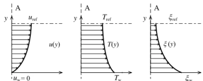
Consider a general forced-convective flow with endothermic reaction due to its chemical decompositions, with three profiles of state-variables as shown in Figure 4. Here, the following assumptions
are introduced: Fluid pressure p is constant in the y direction. Specific heats of the fluid, c
p,ξand h
p,T, are constant in the y direction. Transport properties of the fluid, μ, λ, and κ, are constant in the y direction.
According to Eq. (11), the total heat flux through the fluid in the y direction is written as:
y T q
yT
∂
⋅ ∂
⎟ ⋅
⎠
⎜ ⎞
⎝
⎛
∂
⋅ ∂ +
−
= ξ λ
λ 1 κ
total
, (12)
where, ∂ξ/∂T denotes the ratio of the extent of reaction gradient to the temperature gradient at an arbitrary position y.
For the derivation of the Nusselt number ratio, it is to know is the heat flux at the wall surface (y = 0); due to definition of the Nusselt number. From the Eq. (12) and (9), the heat fluxes at the wall surface with and without chemical decompositions are written as:
0 0 0
total
1
= =
=
∂
⋅ ∂
⎟ ⋅
⎟
⎠
⎞
⎜ ⎜
⎝
⎛
∂
⋅ ∂ +
−
=
y y y y
y T
q T ξ λ
λ
κ , (13)
0 0 phys
=
∂
=⋅ ∂
−
=
y y y
y
q λ T , (14) substituting Eq. (13) and (14) into Eq. (4), then the Nusselt number ratio Nu
*is derived as:
0
*
1
Nu
∂
=⋅ ∂ +
=
T
yξ λ
κ , (15)
where, the second part of the right-hand-side denotes the enhancement of the Nusselt number related to endothermic reactions.
When non-dimensional temperature T
*and non- dimensional extent of reaction ξ
*are defined as:
ref w
ref
w
T T
T T T T T
−
= − Δ
≡ Δ
∗
, (16)
ref w
ref
w
ξ ξ
ξ ξ ξ ξ ξ
−
= − Δ
≡ Δ
∗
, (17) then, from the description of Eq. (15), the relation expression of the Nusselt number ratio for general forced-convective flow with endothermic reaction is derived as:
w phys,
w chem,
Ki
01 Pr
Nu h
h
T
yΔ
⋅ Δ
∂
⋅ ∂ +
=
=
∗
∗
ξ
∗, (18)
where, Pr is molecular Prandtl number. Then, Ki is tentative non-dimensional number defined as Ki ≡
Fig. 4 General profiles of velocity u(y), temperature T(y), and extent of reaction ξ(y) in laminar forced- convective flow with endothermic reactions along a high-temperature wall.
T(y) A y
Tw
Tref
ξw
ξref
(y) A y
ξ u(y)
A y
uw
uref
= 0
μ/(κ/h
p,T); the latter denotes the ratio of kinetic viscosity coefficient v (≡ μ/ρ) to chemico-thermal diffusivity a
κ(≡ κ/ρh
p,T), as well as Prandtl number Pr denotes the ratio of kinetic viscosity coefficient ν to physico-thermal diffusivity a
λ(≡ λ/ρc
p,ξ). (Or, it should be named as chemical Prandtl number Pr
chem).
Then, ∂ξ
*/∂T
*|
y=0is the ratio of non-dimensional gradient of extent of reaction ∂ξ
*/∂y
*to gradient of temperature ∂T
*/∂y
*at the wall surface. Δh
chem,w= h
p,TΔξ
wis difference of the chemical enthalpy between the extent of reaction at the wall (of wall temperature T
w) and the extent of reaction at the reference position (main stream, bulk, or center-line), as well as Δh
phys,w= c
p,ξΔΤ
wis difference of the physical enthalpy between the temperature at the wall and the temperature at the reference position (main stream, bulk, or center-line).
From the definitions of non-dimensionalized enthalpy such as:
ref w
ref
w
h h
h h h h h
−
= − Δ
≡ Δ
∗
, (19) then, Eq. (18) is also described as follows:
p
T
y⋅ Γ
∂
⋅ ∂ +
=
=
∗
∗ ∗
Ki
01 Pr
Nu ξ , (20)
where, Γ
pis the ratio of non-dimensionalized specific heats h
p,T*to c
p,ξ*with constant pressure; it also denotes the ratio of the differences of chemical enthalpy Δh
chem,wto physical enthalpy Δh
phys,w. So the definition of Γ
pby the author is:
( )
( )
ξ( ( ) )
ξξ
ξ
w , phys,
w , chem, ,
, ,
,
p T p p
T p p
T p
p
h
h T
h h c
h
Δ
= Δ
∂
∂
∂
= ∂
≡
Γ
∗ ∗∗
∗
∗
∗
. (21)
On the other hand, the ratio of specific heat γ
ξof constant pressure c
p,ξto constant volume c
v,ξis also defined as:
( )
( )
ξξξ ξ
γ
ξ, , ,
,
v p v
p
T h
T h c
c
∂
∂
∂
= ∂
≡
( )
( ) ( )
( )
ξξ ξξ ξ ξ
ξ
≡ Γ
Δ
= Δ
∂
∂
∂
= ∂
=
∗ ∗∗
∗
∗
∗
w , phys,
w , phys, ,
, ,
,
v p v
p v
p
h h T
h T h c
c , (22)
from this expression of definition of specific ratio of γ
ξ, it can be denoted as therefore the ratio of non- dimensional specific heats with constant extent of reaction.
The relational expression of Eq. (20) may be generally applicable to any forced-convective flow geometries with endothermic reactions; such as flow on a flat plate and flow in a tube, etc. But it should be verified.
Derivation of the Nusselt Number Ratio for Fully Developed Turbulent Forced-Convective Flows with Endothermic Reactions
Fig. 5 shows general profiles of state-variables of velocity u(y), temperature T(y), and extent of reaction ξ(y) in developed turbulent forced-convective flow along a high-temperature wall. In such flow, by analogy with Boussinesq’s hypothesis for turbulent
viscosity, the heat flux with endothermic reacting turbulent flow at an arbitrary y position is described as:
v T y c
q
yT +
p′ ′
∂
− ∂
= λ ρ
,ξphys
, (23)
v y h
q
y+
pT′ ′
∂
− ∂
= κ ξ ρ
,ξ
chem
, (24) hence,
( )
y q
yT
∂ + ∂
−
=
turbphys
λ λ , (25)
( )
q
yy
∂ + ∂
−
= κ κ
turbξ
chem
, (26) or,
( )
y a T a c
q
y p∂ + ∂
−
=
, turbphys
ρ
ξ λ λ, (25)’
( )
a y a h
q
y pT∂ + ∂
−
= ρ
, κ κturbξ
chem
, (26)’
so, from the Eqs. (25) and (26), the total heat flux is described as:
( ) ( )
y y
q
yT
∂ + ∂
∂ − + ∂
−
= λ λ
turbκ κ
turbξ
total
, (27)
where, the second parts of the right-hand-side of Eqs.
(23) and (24) are given by the derived energy equation for turbulent flow with endothermic reaction. For derivation of the energy equation for turbulent flow with endothermic reaction, velocity v, temperature T, and extent of reaction ξ are written as v = v + v’, T = T + T’, ξ = ξ +ξ’; v , T , and ξ are time averages of velocity, temperature, and extent of reaction, respectively. Then v’, T’, and ξ’ are turbulent fluctuations of velocity, temperature, and extent of reaction, respectively. For Eqs. (25) and (26), λ and λ
turbare the coefficient of molar and turbulent physico-thermal conductivity respectively, then κ and κ
turbare the coefficient of molar and turbulent chemico-thermal conductivity respectively. For Eqs.
(25)’ and (26)’, a
λand a
λturbare the coefficient of molar and turbulent physico-thermal diffusivity;
defined as λ/(ρc
p,ξ) and λ
turb/(ρc
p,ξ) respectively. Then, a
κand a
κturbare the coefficient of molar and turbulent chemico-thermal diffusivity; defined as κ/(ρh
p,T) and κ
turb/(ρh
p,T) respectively. Detailed descriptions about Fig. 5 General profiles of velocity u(y), temperature T(y), and extent of reaction ξ(y) in developed turbulent forced-convective flow with endothermic reactions along a high-temperature wall.
T(y) A y
Tw
Tref
ξw
ξref
(y) A y
u(y) ξ A
y
uw
uref
= 0
the derivation of the turbulent energy equation in y direction and the turbulent heat flux in an arbitrary y position are omitted in this paper.
As mentioned above, for the derivation of Nusselt number ratio, it is to know is the heat flux at the wall surface due to definition of the Nusselt number. Hence, it is not necessary to know the behavior of reacting fluid in the turbulent layer which is away from the wall surface. From this reason, first, consider the behaviors in near-wall layer of the fluid; so-called laminar sub-layer.
To describe the Nusselt number ratio in a simple form, introductions of some hypothesis for fully developed turbulent forced-convective heat transfer are described in what follows.
(i) Introduction of Hypothesis in the Prandtl’s Analogy
According to hypothesis in the Prandtl’s analogy, the heat flux through the laminar sub-layer near the wall is constant; That is, the temperature T is proportional to y coordinate in the layer as shown in Fig. 6 (a). Introducing this hypothesis to the extent of reaction, namely, it can be assumed that the extent of reaction ξ is also proportional to y coordinate in the layer. Then, considering the non-dimensional profiles of temperature T and extent of reaction ξ, as shown in Fig.6 (b), it can be allowable that the introduction of a hypothesis as:
1
0
∂ ≅
∂
=
∗
∗
T
yξ , (28)
hence, the Nusselt number ratio denoted in Eq. (20) is
approximated as:
Γ
p⋅ +
≅
∗
Ki 1 Pr
Nu , (29)
(ii) Introduction of Hypothesis in the Reynolds’s Analogy
According to the hypothesis in the Reynolds’s analogy that excludes the existence of laminar sub- layer; that is, all region is takes without the laminar sub-layer. In other words, it is assumed that the whole region is the turbulent layer. Due to this hypothesis—
a
λ<< a
λturband a
κ<< a
κturbin the near-wall layer—
hence the molecular thermal diffusivity coefficients a
λand a
κin Eq. (25)’ and (26)’ are neglected. So the total heat flux at the wall surface with the Reynolds’s hypothesis is described as:
0 turb 0 turb 0 total
= =
=
∂
⋅ ∂
∂ −
⋅ ∂
−
=
y y y y
y y
q λ T κ ξ , (30)
hence, the Nusselt number ratio which introduced the Prandtl’s hypothesis denoted above is described as (dividing Eq. (30) by the turbulent heat flux without the reaction at y = 0):
Γ
p⋅ +
≅
∗
turb turb
Ki 1 Pr
Nu , (31) where, Pr
turband Ki
turbare defined as ν
turb/(λ
turb/(ρc
p,ξ)) and ν
turb/(κ
turb/(ρh
p,T)), respectively; ν
turbis turbulent kinematic viscosity defined as μ
turb/ρ.
In addition, due to the other hypothesis in the Reynolds’s analogy—ν
turb≈ a
λturbin turbulent region—it can also be assumed as v
turb≈ a
κturb; that is, a
λturb≈ a
κturb, hence Pr
turb≈ Ki
turb. Therefore, the following approximation is allowed:
Ki 1 Pr
turb
turb
≅ . (32) As a result of introductions of hypothesis in the Prandtl’s and Reynolds’s analogies, ultimately the Nusselt number ratio is approximated as follows:
Γ
p+
≅
∗
1
Nu . (33) This relational expression of Nu
*and Γ
pis simple for practical use; it is also in a special case Pr/Ki = 1 in Eq. (29) for turbulent flow with laminar sub-layer.
This relation for fluids with low-scale Γ
pis indicated in Fig. 7 (a). This expression denotes also Nu
*is approximately equal to Γ
p, i.e. Nu
*≈ Γ
p, for fluids with high-scale Γ
pas shown in Fig. (b).
The relation expression of Eq. (29) and (33) may be applicable to any flow, because the Nusselt number depends on only the ratio of heat flux at the wall surface due to its definition. Additionally, it may be also applicable to boiling heat transfer; Fig.7 (b) shows also the tentatively predicted Γ
pfor a H
2O boiling heat transfer rate.
Description of the Non-Dimensional Specific Heat Ratio Γ
pThe specific heat ratio Γ
pin Eq. (29) and Eq. (33) is considered as a function of reactant fluid and catalytic Fig. 6 Dimensional and non-dimensional profiles of
the temperature and extent of reaction in a fully developed turbulent forced-convective flow near the wall surface with endothermic reactions.
laminar sublayer
T(y) A y
Tw
Tref ξref ξw
(y) A y
ξ
qphys
y = 0
y qchem
y = 0 y
turbulent layer
(a) Dimensional profiles.
(b) Non-dimensionalized profiles.
laminar sublayer
T (y) A
y
Tw ξw
(y) A
y
ξ
qphys
y = 0
y qchem
y = 0 y
turbulent layer
*
* *
0 *
0 = 1 = 1
substance of the solid wall as follows:
( Reactant , Catalyst )
p p
= Γ
Γ , (34)
where, when the endothermic reaction proceeds, Γ
pdenotes positive value (Γ
p> 0) due to its positive heat of reaction. In contrast, when the exothermic reaction proceeds, Γ
pdenotes negative value (Γ
p< 0) due to its negative heat of reaction; based on the definition of Γ
pin Eq. (21). Then, when no reaction proceeds, Γ
pdenotes zero (Γ
p= 0) due to zero heat of reaction;
therefore Nu
*= 1.
Predicted orders of Γ
pvalue for some hydrocarbon fuels are tabulated in Table 1. Figure 7 (a) and (b) shows the relations of Nusselt number ratio Nu
*and non-dimensional specific heat Γ
pin some Pr/Ki ratio cases.
Description of Nusselt Number Equation
For fully developed turbulent flow in smooth tubes, the following relation is recommended by Dittus and
Boelter
14):
4 . 0 8 . 0
DB
0 . 023 Re Pr
Nu = ; for heating (35)
For example, in a case of that the normal Nusselt number—normal denotes with no chemical reaction—
of turbulent forced-convective flow is predictable from Dittus-Boelter’s correlation equation, the description of enhanced Nusselt number related to the endothermic reaction of the fluid is available as:
( + Γp)
= Nu 1
Nu
total DB( + Γp)
= 0 . 023 Re
0.8Pr
0.41 , (36) here, Re is the diameter-based Reynolds number.
Meanwhile, Pr is molecular Prandtl number denoted above. All properties in Re and Pr are evaluated at the fluid bulk temperature.
Evaluations of Validity and Applicability of the Proposed Relational Expression
To assess the validity and applicability of the proposed relational expression of Eq. (33)—in a special case of Pr/Ki = 1 in Eq. (29)—, comparisons of Nusselt numbers with previously confirmed experimental results are discussed in what follows.
For the comparison, the heated tube test results using supercritical JP-7 fuel carried out by Linne et al. (TM- 107485
12)) at NASA Lewis Research Center is referred. The tests were conducted for the purpose of correcting data concerning the endothermic cooling use of JP-7 fuels for a hypersonic propulsion system;
the report anticipates that coolant-side wall temperature may reach approximately 1,250 K in such propulsion system.
(i) Overview of the Heated Tube Tests at NASA (TM-107485)
According to the report TM-107485
12), the tests was conducted in NASA LRC Heated Tube facility
15)using electrically heated metallic alloy tubes which has 0.095 in. (0.24 cm) of inner diameter, 14 in. (35.5 cm) of heated section length. Operating pressure is 6.9 MPa (Critical pressure and temperature of JP-7 are approximately 1.8 MPa and 677 K respectively). Heat flux is controlled electrically to increase in steps until the desired wall temperature are achieved as shown in Fig. 8. Due to the report, Reynolds number at tube inlet (at ambient temperature) is 5275, and typical Reynolds number at tube exit during a test was 1.4×10
5. In the two test sections of Section 4 and Table 1 Predicted orders of non-dimensional specific heat ratio of Γ
p.
n (m) substance specific heat ratio, Γp
0 (2) H2 0 (w/o dissociation)
1 (4) CH4 ≈ 0
small n CnHm small Γp
large n CnHm large Γp
n ≈ 12 JP-7 ~ 0.9 (approx., see below) n = carbon number.
m = hydrogen number.
1
2 4 6 8
10
2 4 6 8
100
Nusselt ratio, Nu*
0.1 2 4 6 81 2 4 6 810 2 4 6 8100 Specific heat ratio, Γp
for endothermic reactions Γp > 0
Pr/Ki = 1 Pr/Ki = 2
Pr/Ki = 0.5
Supercritical JP-7 Predicted area for a H2O Boiling
(b) For wide-scale specific heat ratio of Γ
p. Fig. 7 Relations between Nusselt number ratio Nu
*and specific heat ratio of Γ
pin some Pr/Ki ratio cases.
(a) For low-scale specific heat ratio of Γ
p.
4.0
3.5
3.0
2.5
2.0
1.5
1.0
Nusselt ratio, Nu*
2.0 1.5
1.0 0.5
0.0
Specific heat ratio, Γp
Pr/Ki = 1
Pr/Ki = 0.5 Pr/Ki = 2 for endothermic reactions
Γp > 0
Section 5—shown below in Fig.11 (a) to (c), and Fig.
12, respectively—, target coolant-side wall temperatures are 1,030 to 1,145 K, and 1,170 to 1,280 K respectively. Maximum heat fluxed in each test sections are 6.5 MW/m
2and 7.4 MW/m
2respectively.
See the report TM-107485
12)for the other details about the tests.
(ii) Evaluation of Specific Heat Ratio Γ
pand Nusselt Number Ratio Nu
*for supercritical JP-7 fuel
For evaluation of ratio of specific heat Γ
pdefined as in Eq. (21), the temperature dependence of chemical heat sink characteristics of supercritical JP-7 evaluated (at a pressure of 4.1 MPa) by Huang et al.
6)at United Technologies Research Center. Figure 9 shows it as a function of fluid bulk temperature T
b, corresponding to the physical heat sink (i.e. sensible heat sink) characteristics estimated by NIST SUPERTRAPP.
5
4
3
2
1
0 Heat sink, h-h0 (298.15 K), MJ/kg
1400 1200 1000 800 600 400 200
Bulk temperature, Tb, K
Endothemic fuels , JP-7 (P=4.1MPa) , JP-8+100 (P=4.1MPa) , n-octane (P=4.1MPa)
Physical heat sink (NIST SUPERTRAPP)
Endothermic effect (Chemical heat sink)
Experimental plots are referred from:
Huang, H. et al, ASME J. Eng. Gas T urbines Power, Vol.126, 284, Apr., 2004.
Fig. 9 Evaluated relations between the physical and chemical heat sinks for typical hydrocarbon fuels at supercritical pressure of 4.1 MPa
6).
Fig. 8 Histories of temperatures and a heat flux at the heated tube test using endothermic JP-7 fuel (TM-107485
12)); Test Section 4.
1400 1200 1000 800 600 400 200
Temperature, T , K
1000 800 600 400 200 0
Operating time, t, sec
12 10 8 6 4 2 0
Heat flux, q, MW/m 2
Coolant-side wall Temp. (at 2 in.) Coolant Temp. (outlet) Heat flux
298.15 K line Section 4 ; referred to TM-107485
Operating Press. = 6.9 MPa time range 533 - 903 sec (370 sec) Tw at 2 in. = 1033 - 1144 K Max. carbon dep. = 900 μg/cm^2
Table 2 Predicted values of Γ
pand Nu
*for supercritical JP-7 fuel using the results in TM- 107485
12).
(a) For near-inlet conditions.
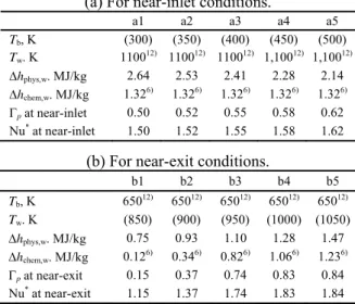
a1 a2 a3 a4 a5 Tb, K (300) (350) (400) (450) (500) Tw. K 110012) 110012) 110012) 1,10012) 1,10012)
Δhphys,w. MJ/kg 2.64 2.53 2.41 2.28 2.14
Δhchem,w. MJ/kg 1.326) 1.326) 1.326) 1.326) 1.326) Γp at near-inlet 0.50 0.52 0.55 0.58 0.62 Nu* at near-inlet 1.50 1.52 1.55 1.58 1.62
(b) For near-exit conditions.
b1 b2 b3 b4 b5 Tb, K 65012) 65012) 65012) 65012) 65012) Tw. K (850) (900) (950) (1000) (1050)
Δhphys,w. MJ/kg 0.75 0.93 1.10 1.28 1.47
Δhchem,w. MJ/kg 0.126) 0.346) 0.826) 1.066) 1.236) Γp at near-exit 0.15 0.37 0.74 0.83 0.84 Nu*at near-exit 1.15 1.37 1.74 1.83 1.84 Parenthetic values are presumed unknown values.
Tb
=
Mean fluid temperature.Tw
=
Coolant-side wall temperature.Δhphys,w = Physical heat sink.
Δhchem,w = Chemical heat sink.
Fig. 10 Predicted values of Γ
pand Nu
*of supercritical JP-7 fuel using the reported experimental results of heated tests of TM-107485
12). (a) For the near-inlet condition (at 1 in.); as a fuction of unknown fluid temperature of T
b.
2.0 1.8 1.6 1.4 1.2 1.0 0.8 0.6 0.4 0.2 0.0
Γp, Nu*
1200 1000 800 600 400 200
Bulk temperature, Tb, K Evaluated values of Γp and Nu*
for near-inlet conditions (at 1 in.; TM-107485) - Tw =1,100 K - Tb = unknown Nu*
Γp
2.0 1.8 1.6 1.4 1.2 1.0 0.8 0.6 0.4 0.2 0.0
Γp, Nu*
1200 1000 800 600 400 200
Wall temperature, Tw, K Evaluated values of Γp and Nu*
for near-exit conditions (at 13 in.; TM-107485) - Tw = unknown - Tb = 650 K
Nu*
Γp
(b) For the near-exit condition (at 13 in.); as a
function of unknown wall temperature T
w.
The values of Γ
pand Nu
*evaluated due to near inlet (at 1 in. of total heated length of 14 in.) conditions are tabulated in Table 2 (a). Here, the fluid bulk temperature data is not available in TM-107485.
Hence the Γ
pand Nu
*values are indicated as a function of the unknown fluid bulk temperature of T
b, as shown in Fig. 10 (a). On the other hand, the values of Γ
pand Nu
*evaluated due to near-exit (at 13 in. of total heated length of 14 in.) conditions are tabulated in Table 2 (b). Here, the wall temperature data is not available in TM-107485. Hence the Γ
pand Nu
*values are indicated as a function of the unknown wall temperature of T
w, as shown in Fig. 10 (b). The near- inlet condition, which indicates a large difference between the wall and fluid bulk temperature, denotes stable Γ
pvalues of 0.50 to 0.62. On the other hand, the near-exit condition, which indicates a relatively small difference between the wall and fluid bulk temperature, denotes unstable Γ
pvalues of 0.15 to 0.74 at lower wall temperature. However, it denotes stable Γ
pvalues of 0.74 to 0.84 at higher wall temperature over 950 K.
(iii) Evaluation and Comparison of the Enhanced Nusselt Numbers
According to TM-107485
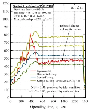
12), a consistent feature was determined that the experimental Nusselt numbers in the beginnig—without chemical decompositions due to low heat fluxes—of every test most closely resembled the Dittus-Boelter’s correlation of Eq. (35).
It is confirmed also in the following Figs. 11 (a) to (c) and 12; before 160 sec of operating time of the test Section 4 as shown in Fig. 11 (a) to (c); before 60 sec
of operating time of the test Section 5 as shown in Fig.
12. That is, this fact represent that Nusselt numbers of supercritical JP-7 fuel without chemical decompositions can be predicted by the Dittus- Boelter’s correlation equation with comparatively high accuracy. Therefore, this fact allows that the Nu
physis substituted by the Nusselt number Nu
DBin Eq. (33)—
as denoted in Eq. (36)—for evaluation of Nu
totalvalues.
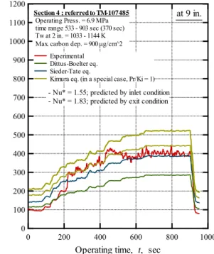
Figure 11 and 12 indicates the comparison results of Nusselt numbers; evaluated by experimental, Dittus- Boelter’s correlation, Sieder-Tate’s correlation, and the proposed correlation (Nu
total= Nu
DB(1+Γ
p) denoted in Eq. (36) due to confirmed consistent features mentioned above). Corresponding temperature histories and heat flux history (at the beginning of chemical decomposition) of Section 4 are indicated above in Fig. 8 for reference. In these figures, fluctuation of experimental Nusselt number curves are not reproduced strictly; mean values are plotted in these figures. See TM-107485 for original experimental curve with fluctuations due to chemical decompositions.
Fig. 11 (a) indicates the Nusselt number curves at 1 in. (near-inlet) of total heated length of 14 in. in Section 4. From these curves, it is confirmed that after the decomposition occurs at 160 sec, the Nusselt number curve which evaluated by the proposed relation due to near-inlet condition (Nu
*= 1.55) well accorded with the experimental Nusselt number curve from beginning to end, as well as Sieder-Tate’s correlation curve.
Fig. 11 (b) indicates the curves at 9 in. of total heated length in Section 4. These curves represents
Fig. 11 (b) The comparison result of overall Nusselt numbers between experimental value (TM- 107485
12)) and some correlated equation values; Test Section 4: Haynes 230, at 9 in. of total heat length of 13 in.
1200 1100 1000 900 800 700 600 500 400 300 200 100 0
Nu
1000 800
600 400
200 0
Operating time, t, sec
at 9 in.
Section 4 ; referred to TM-107485 Operating Press. = 6.9 MPa time range 533 - 903 sec (370 sec) Tw at 2 in. = 1033 - 1144 K Max. carbon dep. = 900 μg/cm^2
Experimental Dittus-Boelter eq.
Sieder-Tate eq.
Kimura eq. (in a special case, Pr/Ki = 1) - Nu* = 1.55; predicted by inlet condition - Nu* = 1.83; predicted by exit condition
Fig. 11 (a) The comparison result of overall Nusselt numbers between experimental value (TM- 107485
12)) and some correlated equation values; Test Section 4: Haynes 230, at 1 in. (near inlet) of total heat length of 13 in.
1000
900
800
700
600
500
400
300
200
100
0
Nu
1000 800
600 400
200 0
Operating time, t, sec
- Nu* = 1.55; predicted by inlet condition - Nu* = 1.83; predicted by exit condition Section 4 ; referred to TM-107485
Operating Press. = 6.9 MPa time range 533 - 903 sec (370 sec) Tw at 2 in. = 1033 - 1144 K Max. carbon dep. = 900 μg/cm^2
at 1 in.
Experimental Dittus-Boelter eq.
Sieder-Tate eq.
Kimura eq. (in a special case, Pr/Ki = 1)