http://dx.doi.org/10.7839/ksfc.2013.10.1.029
SimMechanics SimHydraulic을 이용한 가상 굴삭기 개발
Development of a Virtual Excavator using SimMechanics and SimHydraulic
레광환
1․정영만
1․웬치탄
1․양순용
2*Q. H. Le, Y. M. Jeong, C. T. Nguyen and S. Y. Yang
Received: 16 Nov. 2012, Revised: 25 Feb. 2013, Accepted: 27 Feb. 2013
Key Words:Hydraulic System (유압 시스템), Virtual Excavator (가상 굴삭기), Control(제어), Dynamics (동역
학), Simulation (시뮬레이션)
Abstract: Excavation is an important work in mining, earth removal and general earthworks. Nowadays,
automation in excavator has been studied by several researchers. In the excavator research methods, simulation is one of the low cost methods for applied to test safely. In this paper, designed a virtual hydraulic excavator that with the control and the dynamic. At first, the simulation of hydraulic system for excavator’s attachment such as boom, arm and bucket using Matlab/Simhydraulic is presented. Second, the dynamic model of excavator is distributed to combine with the hydraulic system. For controlling this system, electric joysticks are used to operate the orifice open areas in Main Control Valve. The simulation result is described to analysis the performance of this virtual excavator.
* Corresponding author: [email protected]
1 Department Mechanical Automotive Engineering Graduate School of University of Ulsan, Ulsan, 680-749, Korea
2 Department of Mechanical and Automotive Engineering, University of Ulsan, Korea.
Copyright Ⓒ 2013, KSFC
This is an Open-Access article distributed under the terms of the Creative Commons Attribution Non-Commercial License (http://
creativecommons.org/licenses/by-nc/3.0) which permits unrestricted non-commercial use, distribution, and reproduction in any medium, provided the original work is properly cited.
기호 설명
θ θ
θ
θ
θ
: measured joint angles D
α(θ) : inertia
C
α(θ, ) : Coriolis and centripetal effects G
α(θ) : gravity forces
B
α( ) : friction
τ : corresponding input matrix
τ
α=[ τ
1τ
2τ
3τ
4]
Τ: specifies the torques acting on the shafts
F
L: interactive torques between the bucket
and the environment during the digging operation
1. Introduction
In the construction, mining, agriculture and wasted disposal fields, no other tool has been more versatile than the excavator.
A large amount of these machines, whose design has remained hugely unchanged for decades, are currently in service worldwide.
Simplicity and reliability are key factors
contributing to success of this design. However,
contrary to this expected increase in equipment
demand, the abundance of skilled operators is
declining because it usually requires 3~5 years of
handling experience to become a skilled excavator
operator and the working conditions at
construction sites are poor. To solve these
problems, much research on automating excavator
operations is being conducted [1‐4]. In addition to
automation of the hydraulic excavator, there is also research being conducted on its modeling. A dynamic model of the excavator can be used for development of an automation algorithm and the subsequent testing of this algorithm without incurring high costs [2, 5]. The model can also be applied to various situations such as simulation training for excavator operators [6] or estimation and analysis of systems’ characteristics. However, these studies [1‐6] have not been progressed considerably. Specially, the model combined hydraulic system and mechanical system of the excavator. In this paper, a virtual excavator included the hydraulic system and dynamic model was contributed and developed using SimMechanics and SimHydraulic of Matlab/
Simulink software. In this study, the performance of the virtual excavator’s attachment such as boom and arm and bucket will be described. In addition, user can visualize and verify dynamic system behavior of virtual excavator in a virtual reality environment through the user interface.
2. Virtual Excavator
The virtual excavator can be considered as a subsystem that includes dynamic system and hydraulic system. Also the virtual excavator includes the operation signal and 3D graphics monitor interface. In this study, the system is modeled to approach of the 1.5 tons excavator class of D company such as mechanical parameters, hydraulic circuit and components etc.
Fig. 1 Structure of virtual excavator
The structure of the virtual excavator is shown in figure 1. The dynamic system and the
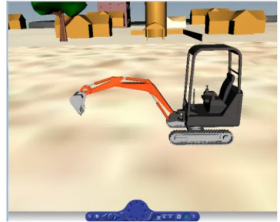
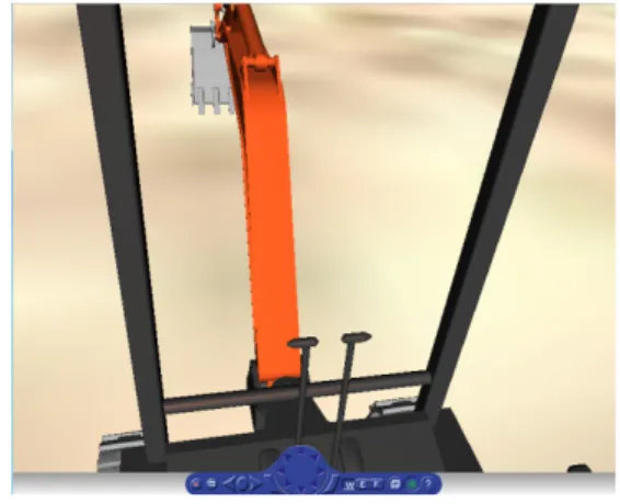
hydraulic system are modeled by using the Simcapse toolbox of Matlab/Simulink software. In addition, 3D graphics for monitor interface shown in figure 2 is contributed by using 3D animation toolbox. These toolboxes are from Matlab/
Simulink software so it is very compatible and convenient to connect and collect data between the subsystems.
Fig. 2 3D graphics for monitor interface
3. Dynamic model of virtual excavator
The dynamic model of excavator can be expressed concisely using the form of the well‐
known rigid‐link manipulator equations of motion:
αθθ̈
αα
θθ̇
αθ
αθ̇ Γτ
α
(1)
In this paper, the dynamic model of the excavator is designed by using the SimMechanics software. At first, the 3D CAD model is created by Solidworks software. Second, the SimMechanics model is built by translate from the 3D CAD model.
3.1 3D CAD model of excavator
The 3D model of 1.5 ton excavator class of D
company is distributed by using CAD software is
shown in figure 3. In this model, the parameters
applied real excavator parameters such as mass
and the length of parts and inertia moment. And
revolute joints are used to connect of each module
such as lower‐base and upper‐base and boom and
arm and bucket.
Fig. 3 3D model of excavator
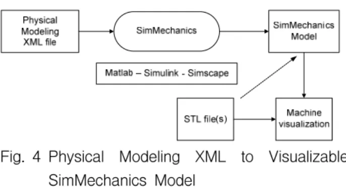
3.2 3D CAD model of SimMechanics model The first translation step is to use the SimMechanics link exporter to create an intermediate physical modeling XML file from a CAD assembly. The second translation step is to import the physical modeling XML to generate the SimMechanics model then use that model together with the body geometry graphics files to simulate and visualize the original mechanical system. The process is described in figure 4.
Fig. 4 Physical Modeling XML to Visualizable SimMechanics Model
When the model is imported completely, the Simechanics model will appear in the Simulink windows.
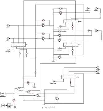
Fig. 5 SimMechanics model of excavator
The figure 5 is shown the result of excavator model. In this excavator, the kinds of joint are
revolute joint and prismatic joint. The revolute joints connect the upper‐base, lower‐base, boom system, arm system and bucket system likely an arm robot. The prismatic joints represent the connection of between the rod and the tube of each cylinder attached to boom arm and bucket.
4. Hydraulic model of the virtual excavator using SimHydraulic
4.1 Main Control Valve (MCV)
The MCV consists of various valves for boom, arm, bucket, travel motor, dozer and swing etc.
Only the valves of boom, arm and bucket are considered in this paper. These valves are 6 ports 3 position types including bypass circuits. An example of modeling for boom 6/3 directional valve is presented below.
The figure 6 is shown a circuit diagram of a boom valve. When spool is in neutral, the bypass line is completely open. If pilot pressure act to one side of a valve selectively, spool is moved in accordance with the pressure. Then the open‐area shows a non‐linear relation with spool displacement as same to the figure 7.
Fig. 6 Circuit diagram of the boom valve
Fig. 7 Stroke‐Open area characteristics of the
boom valve
The boom valve is designed in order to include the direction of spool and non‐linear open‐area using the SimHydraulic as shown in figure 8.
Fig. 8 Model of the boom valve using SimHydraulic
4.2 Pump
An applied field robot has got three hydraulic pumps. The pump is used to control pilot pressure. The orders are fixed capacity type each flowing out 5.1cc/rev. A pump mainly takes charge of the movement of the arm. And a pump 2 usually concern with motion of boom and bucket. When the cylinder need much flow rate, pump 2 can concern with the operation through a check valve.
4.3 Cylinder
Attachment is moved by stroke variation of three cylinders. The specification of cylinders is shown in the Table 1. In this study, the weight of cylinders has been ignored.
Table 1 Specification of cylinders Cylinder
Boom Arm Bucket
Piston
diameter 55mm 55mm 55mm
Rod diameter 30mm 30mm 30mm
Length of
stroke 250mm 390mm 245mm
4.4 Modeling of the hydraulic system
The hydraulic system is made completely and described in figure 9. The hydraulic simulator system for field robot is completed by assembly of each component. The models of the attachment and valves are setting up to each separate super component.
Fig. 9 The hydraulic system Model
This simulator system works according to input signals having range of ‐7 mm to 7 mm which they move valve spools. Relief valves set up the maximum pressure in the system to 210 bar. Two pumps turn to the same speed because they are connected with the only engine. And the flow rates are also same.
5. The performance of the virtual excavator
The virtual excavator is built the hydraulic and
dynamics system completely is described in the
previous chapters. In this chapter, the performance
of the virtual excavator is presented with some
simulation result. The modeling of the system
includes the control; hydraulic and dynamics
subsystem was shown in figure 10.
Fig. 10 The modeling of the system
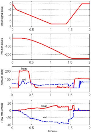
In this simulation, the performance of the virtual excavator is verified through analysis the flow rate and the pressure of cylinders. Besides, there is only consisting the movement of the attachment so the collaborative between the hydraulic system and dynamic model would be concentrated to verify the operating of virtual excavator. In addition, this study ignores the joint friction and the interactive force between the bucket and the soil ground so the elements include inertia and Coriolis and centripetal effects and gravity forces are considered during the operating of the virtual excavator. Therefore, for testing this system, the task design is not a complex movement of attachment for common excavator working as digging or lifting etc. In this case, the task is only designed to test the hydraulic system under the effects of the dynamic system. Specifically, a task which cylinder runs full length of stroke from the initial position to finally position to verify the state as start and moving and stop should be designed. At first, the input signals of the joysticks are set to operate the orifice open areas in MCV. Second, the stroke cylinder position and pressure and flow rate of the head and rod of cylinder are verified that the responds of them are suitable or not from the change of MCV.
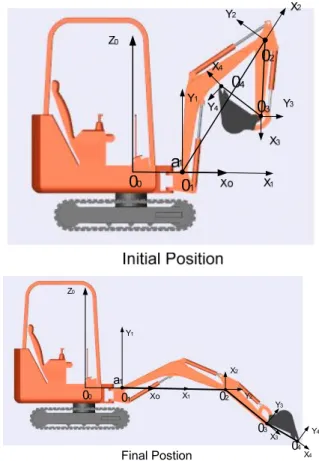
A simulation is designed with the input value that has set from 0 mm to ‐7 mm. This value means the stroke's displacement of MCV and the displacement set from 0 mm to 7mm and the direction movement which marks by minus symbol. This means cylinder retraction. The cylinders of boom, arm and bucket retracted completely from the maximum extended positions shown in figure 11. This means the cylinders
move full length of their stroke displacement.
Final Postion a1
Xo X1
X4
Y1
Y3
Y4
01 02
04
Z0
X3
Y2
03
00
X2