RVR에 의한 자율주행로봇의 정밀제어에 관한연구
A Study on Precise Control of Autonomous Travelling Robot Based on RVR
심병균
1*
, Nguyen Huu Cong2
, 김종수3
, 하언태4
Byoung-Kyun Shim, Nguyen Huu Cong, Jong-Soo Kim, Eun-Tae Ha
<Abstract>
Robust voice recognition (RVR) is essential for a robot to communicate with people.
One of the main problems with RVR for robots is that robots inevitably real environment noises. The noise is captured with strong power by the microphones, because the noise sources are closed to the microphones. The signal-to-noise ratio of input voice becomes quite low. However, it is possible to estimate the noise by using information on the robot’s own motions and postures, because a type of motion/gesture produces almost the same pattern of noise every time it is performed.
In this paper, we propose an RVR system which can robustly recognize voice by adults and children in noisy environments. We evaluate the RVR system in a communication robot placed in a real noisy environment. Voice is captured using a wireless microphone. Navigation Strategy is shown Obstacle detection and local map, Design of Goal-seeking Behavior and Avoidance Behavior, Fuzzy Decision Maker and Lower level controller. The final hypothesis is selected based on posterior probability.
We then select the task in the motion task library. In the motion control, we also integrate the obstacle avoidance control using ultrasonic sensors. Those are powerful for detecting obstacle with simple algorithm
Keywords : Robust voice recognition, Navigation Stratgy
1*정회원, 교신저자, 경남대학교 첨단공학과, E-mail:[email protected]
2정회원, 미쉐린베트남(주)
3정회원, 한국소방안전협회, 교수, 工博
4정회원, 미래기술연구소, 연구소장
*Corresponding Author, Dept. of Advanced Engineering, Kyungnam University.
2Michelin Vietnam Co., Ltd.
3Prof., Korea Fire Safety Association, Ph. D.
4Director, Future Technology Institute Co., Ltd.
1. INTRODUCTION
To make human-robot communication natural, it is necessary for the robot to recognize voice even while it is moving and performing gestures. For example, a robot’s gesture is considered to play a crucial role in natural human-robot communication1)-8). In addition, robots are expected to perform tasks by physical actions to make a presentation. If the robot can recognize human interruption voice while it is executing physical actions or making a presentation with gestures, it would make the robot more useful.
Each kind of robot motion or gesture produces almost the same noises every time it is performed. By recording the motion and gesture noises in advance, the noises are easily estimated. By using this, we introduce a new method for RVR under robot motor noise. Our method is based on three techniques, namely, multi-condition training, maximum-likelihood linear regression (MLLR), and missing feature theory(MFT).
These methods can utilize pre-recorded noises as described later. Since each of these techniques has advantages and disadvantages, whether it is effective depends on the types of motion and gesture. Thus, just combining these three techniques would not be effective for voice recognition under noises of all types of motion and gestures. The result of an
experiment of isolated word recognition under a variety of motion and gesture noises suggested the effectiveness of this approach. In what follows, Section 3 discusses the design of voice recognition system, and Section 2 explains our method for avoid the obstacles by navigation strategy. Section 4 describes the recognition, navigation experiments, and the results, before conclusion and mentioning future work in Section 5.
2. VOICE RECOGNITION SYSTEM
2.1. Overview
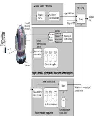
Accounting for the two problems (caused by noisy environments and differences on speaker age) described in Section 1, we developed an RVR system to be robust to both background noise and speakers of different ages. Fig. 1 shows the structure of our RVR system. It consists of three major blocks.
The first block is a front-end processing. It contains a microphone wireless transmitter.
The real-time wireless microphone system for
suppressing interference and noise and for
attenuating reverberation consists of an
outlier-r obust generalized side-lobe canceller
(RGSC) and feature-space noise suppression
(MMSE).
Fig. 1. The structure of the RVR system robust to noise and speakers.
MMSE noise suppression is applied after RGSC to reduce the residual noise at the RGSC output. After that, the voice activity period detected by the GMM-based end- point detection (GMM-EPD) is transferred to the second block. In the second block, there are two decoders depending on the age of the speaker (adult or child); each decoder works using gender-dependent acoustic models.
Noise- suppressed voice at the first block is recognized using these two decoders, and one hypothesis is selected based on posterior probability. The following sub-sections describe each module of our RVR system.
2.2. Eliminating disturbance & noise of robust voice recognition
So far, t his sect i on dis cuss es whi ch techniques are suitable for RVR under robot tasks that make some disturbances and noises to the quality of voice. A common technique is multi-condition training. It trains the acoustic
Fig. 2. Block diagram of the proposed method.
model on voice data to which disturbances and noises are added. This technique improves RVR performance when an input signal includes the disturbances and noises added in training the acoustic model. This has a characteristic that it is easy to cope with stationary disturbances and noises rather than non-stationary ones.
So, we expect that this is effective for
voice recognition in performing a motion or a
gesture that produces stationary disturbances
and noises. MLLR also improves the robustness
of RVR by using an adaptation technique with
the affine transform. MLLR adaptation for a
multi-condition acoustic model is more
effective in voice recognition than that for an
acoustic model trained on clean voice, because the performance of voice recognition using the multi-condition acoustic model is originally higher. Actually, we confirmed this through a preliminary experiment. Preparing multi-condition acoustic models for all kinds of task disturbances and noises without using MLLR would be time-consuming. In addition, it might suffer from over-fitting. Missing Feature Theory (MFT) is proposed to cope with noisy voice input. When there are disturbances and noises, some areas in the spectro-temporal space of voice are unreliable as acoustic features.
MFT-based methods show high noise-robustness against both stationary and non-stationary disturbances and noises when the reliability of acoustic features is estimated correctly. One of the main issues in applying them to RVR is how to estimate the reliability of input acoustic features correctly. Because the signal-to-noise ratio (SNR) and the distortion of input acoustic features are usually unknown, the reliability of the input acoustic features cannot be estimated.
So, the Sonar Sensers-based method is not suitable for the robot. In addition, the size of a total system tends to be large. This means that the number of parameters for the system increases and more computational power is required by the system. Because the room and computational power a robot can use are limited, they are hard problems when being applied to a robot. Therefore, we focus on single channel approaches in this paper.
Consequently, we use multi- condition acoustic model training, MLLR, and MFT.
3. NAVIGATION STRATEGY
3.1. Obstacle detection and local map
As shown in Fig. 3: the RVR robot has three wheels; two driven wheels fixed at both sides of the mobile robot and onecastor attached at the front and rear side of the robot. The ultrasonic sensors are mounted around of the mobile robot in middle layer for the detection of obstacles with various heights. In this study, a sonar array composed of 12 ultrasonic sensors cannot be fired simultaneously due to cross talk.
Instead, we adopt a scheduled firing method where sensors are activated in sequence of {s1, s12, s2, s11 …}. Fig. 3 shows the arrangement of the ultrasonic sensors in upper layer and the sensors are marked as dots in the figure.
The distances ( j = 1, 2,…12) from the origin of the robot frame {R} to obstacles detected by the sensor , can be defined as . Here, Rr is the radius of the robot and the , is the range value measured by the sensor .
A local map is introduced to record the
sensory information provided by the 12
sonar sensors with respect to the mobile
robot frame {R}. As shown in Fig. 3, a
sector map defined locally at the current
mobile robot frame is introduced. Then, the
obstacle position vector ′ with respect to
the frame {R}' can be calculated by
Fig. 3. The local map defined at the frame {R}.
ú ú ú ú
û ù
ê ê ê ê
ë é
- -
-
=
1 0
0 0
0 1
0 0
/ ) cos 1 ( 0 cos sin
/ sin 0
sin cos
' p
p
Se j dq dq dq r
r dq dq
dq
(1) where sej denotes the obstacle position vector defined at the frame { R }. Hence, when the mobile robot is located at a point 0'. the distance value ′ ∥ ′ ∥
from the origin of the frame {R}' to the obstacle and angle ′can be calculated by Eq.(1) . Here, ||.|| denotes Euclidean norm.
The local map defined at the frame {R}' is newly constructed by using the previous local map defined at the frame (R} as follows:
Fig. 4. The coordinate transformation for updating the local map
N N j
INT s n Se
Se
n j j ; 1,2,..., ) 2( ,
'
' = + =
¬
j
j
(2)
Where ← and INT denote the updating operation and integer operation, respectively. Here, sen, denotes the distance value of n th sector and N represents the number of the sector. If the range values obtained by sensors when the mobile robot is located at a point o' are ( j = 1,2 ,...
12, the new local map is partially updated as follows :
sej ← ej, j = 1,2 .... 12. The maximum range of the sonar sensor is set to be
m ax m ax Any return range which is larger than is ignored.
3.2. Design of Goal-seeking Behavior and Avoidance Behavior
The primitive behaviors may be divided as
follows: goal-seeking behavior, ball-following
behavior, keep-away behavior, free space explorer and emergency stop, etc. The output of a primitive behavior is defined by the vector
T
T v t w t Tms
t t v t
u ( ) = ( ( ), D
q( )) = ( ( ), ( ), ) (3)
where t and Tms denote the time step and the sampling time, respectively. Here, T denotes the transpose and denotes the angular velocity of the robot.
We will divide the primitive behaviors into two basic: avoidance behavior and goal-seeking behavior.
The avoidance behavior is used to avoid the obstacles irrespective of the goal position, while the goal-seeking behavior is used to seek the goal position irrespective of obstacle location. Design of each behavior proceeds in following sequences;
(A) fuzzification of the input/output variables, (B) rule base construction through reinforcement learning, (C) reasoning process, (D) defuzzification of output variables.
In order for the mobile robot to arrive at the goal position without colliding with obstacles, we must control the mobile robot motion in consideration of the obstacle position Xoi, = (xoi, yoi ), the mobile robot position X = (x, y) and its heading angle with respect to the world coordinate frame {W} shown in Fig. 5.
In order to avoid the increase in the dimension of input space, the distance values ( i = 1.2,3,4 ) are defined by
Fig. 5. The coordinate frames and control variables
) , , min(
) , , min(
) , , min(
) , , min(
12 11 10 4
9 8 7 3
6 5 4 2
3 2 1 1
se se se d
se se se d
se se se d
se se se d
=
=
=
=
(4)
As shown in Fig. 5.∅ ≤ ∅ ≤ denotes the orientation of a sector with the shortest range. We choose the input variables for avoidance behavior as ∅ and
∥
∥ for goal- seeking behavior as heading angle difference
and distance to goal
∥
∥. The
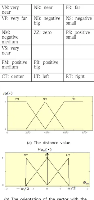
input linguistic variables ∅ and
are expressed by linguistic values (VN, NR,
FR), (NB, NM, NS, ZZ, PS, PM, PB), (LT, CT,
RT) and (VN, NR, FR, VF), respectively. Their
membership functions are expressed as
shown in Fig. 6 and the linguistic terms have
the following meanings.
VN: very
near NR: near FR: far
VF: very far NB: negative
big NS: negative
small NM:
negative medium
ZZ: zero PS: positive small VS: very
near
PM: positive
medium PB: positive big
CT: center LT: left RT: right
(a) The distance value
(b) The orientation of the sector with the shortest range value
(c) The distance to goal position
(d) The heading difference
(e) The linear velocity of mobile robot for the k-thbehavior
(f) The incremental steering angle for k-thbehavior
Fig. 6 The membership functions of the input-output variables
3.3. Fuzzy Decision Maker
New method of selecting an appropriate
behavior has been proposed among many
primitive behaviors by using a fuzzy
decision maker. Let be
a set of motion commands resulting from
the primitive behaviors and
a set of fuzzy goals by which the suitability of a behavior is judged. The j-th fuzzy goal is characterized by their membership functions
. In what follows, the tilde sign(~) representing the fuzzy sets will be dropped for notational simplicity. However, there are some cases where some goals are of greater importance than others. In such cases, fuzzy decision function D might be expressed as the intersection of the goals with the weighting coefficients reflecting the relative importance of the constituent terms. The problem is then to determine one of alternatives with the highest degree of suitability with respect to all relevant goals . To this end, the fuzzy set decision D in discrete space is defined by
{ }
{ }
ú û ù ê ë
é
=
= =
m j n i
w u
D u i G i j
...
2 , 1
; ...
2 , 1
).
( min
, m
(5) where
Here, the coefficient
denotes the importance of goal . The optimal motion command is defined as the output with the highest degree of membership in D.
When the mobile robot is located at O, as shown in Fig. 4, the repulsive and attractive potentials at the point can be calculated, respectively. Suppose that the mobile robot moves from a point O to a point O’ along the path shown in the
figure by the output vector of each behavior. The two potentials at a point O’
then can be calculated, respectively. Using the above potentials, the differences between potential values at O and O’ are calculated.
Thus, when the output of each behavior is applied to the mobile robot, the changes of the repulsive and attractive potentials can be calculated by ∆ and ∆ , respectively. Using the above values, we define three fuzzy goals as follows:
G1: the change in the repulsive potential
should be smaller than c1 G2: the change in the attractive potential
should be smaller than c2 Gi: the repulsive potential should
be smaller than E1
The c1, c2 and E1, are the constants determined by the simulations. The membership functions of the fuzzy goals are defined in the reference(7).
3.4. Lower level controller
The mobile robot posture is represented by three variables. The location of a point (x(t), y(t)) and the orientation taken counterclockwise from the X-axis of the world coordinate frame {W}. The mobile robot posture is defined by a vector.
(6)
The mobile robot kinematics can be expressed by a set of the following differential equations.
cos
sin
(7)
Where,
,
(8)
The robot motion is controlled by its linear velocity and rotational velocity . In order to control the mobile robot, the reference posture and the current posture shown in Fig. 7 are used. The reference posture is calculated by the reference velocity which is determined by the
Fig. 7. The mobile robot postures and error posture
output of a behavior selected by fuzzy decision maker. If the output of the selected behavior is ∆ , the velocity
is defined as ∆ . In order for mobile robot to have the reference velocity at the reference position, the velocities of two wheels must be controlled.
The purpose of this tracking controller is to make the error posture converge to 0. To achieve this, target velocities are calculated by using the error posture and reference velocities.
4. EXPERIMENTS AND RESULT
4.1. Experimental conditions
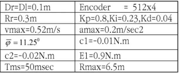
All the parameters used in the navigation experiments are given in Table 1. The mobile robot has the maximum travel speed of 0.52 m/s and the maximum steering rate of 1.854 rad/sec. Experiments are performed in an indoor with the first experiment for voice recognition without objects and second experiment for both of them: voice recognition and obstacles avoidance.
Dr=Dl=0.1m Encoder = 512x4 Rr=0.3m Kp=0.8,Ki=0.23,Kd=0.04 vmax=0.52m/s amax=0.2m/sec2
25 0
. 11
j = c1=-0.01N.m
c2=-0.02N.m E1=0.9N.m
Tms=50msec Rmax=6.5m
Table 1. The parameter values
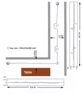
The first experimental space is approxi- mately 9.4m by 1.475m wide, and the second experimental space is approximately 14.2m by 2.5m wide. Fig. 8 shows a sketch of the top view of the room with the object drew in the box shape. Since this environment is too simple to test the performance of the overall system, several polygon obstacles were randomly placed in the path of the mobile robot navigation. The mobile robot was initially located at the origin of the world coordinate frame {W} and the goal of the first experiment was that robot goes straight until someone speaks “turn left”.
Then, the second experiment was active, respectively.
4.2. Experimental results
Fig. 8 shows the location of obstacles, the robot trajectory and its heading angle with respect to world coordinate frame when the robot travels from start position to goal position. The mobile robot trajectory and heading angle shown in the figure were calculated by the dead reckoning system. The navigation results are shown when the polygon obstacles are located in the course of the mobile robot navigation. From the beginning, the robot moves towards according to the voice “forward” of the speaker. The r obo t ’ s p os i t i o n i s ca l cul at ed by t he trajectory-seeking behavior. Then, robot turns left according to the voice “turn left” of speaker. The second experience is robot
moves toward by the voice “forward”. the voice “turn left” of speaker. The second experience is robot moves toward by the voice “forward”. If the robot encounters the obstacles, it avoids the obstacles by using the avoidance behavior. The behavior to be used
(a) Indoor environment
(b) Voice recognition interface
(C) Obstacle detection using ultrasonic sensors
(D) Experimental results
Fig 8. The indoor environment for voice recognition and navigation experiments
at the present situation is selected by fuzzy decision maker. As can be seen from the figure, the robot can successfully navigate in unknown environments even if the environments are not used for constructing the rule bases of the two behaviors in the simulations. This means that the robot can adapt to new environments.
Through a series of the navigation experiments, it was observed that the
heading angle error is a serious problem to mobile robot navigation relying on dead reckoning The large heading angle error almost resulted from the wheels’ slippage when the mobile robot changes its direction Even if the wheel slippage occurs, the true position and heading angle of the mobile robot could be updated by two beacon pairs and consequently the mobile robot could arrive at the given goal position while avoiding the obstacles.
5. CONCLUSIONS
We have proposed the integration of robust
voice recognition and navigation system
capable of performing autonomous navigation
in unknown environments. In order to
evaluate the performance of the overall
system, a number of experiments have been
undertaken in various environments. The
experimental results show that the mobile
robot with the complete voice recognition
and navigation system can arrive at the goal
position according to the desire of speaker
even if the wheel slip occurs. From the
developed of voice recognition and navigation
system, it was observed that the mobile robot
can successfully arrive at the desired position
through the unknown environments without
colliding with obstacles.
REFERENCES
1) S. Kim, K. Seo, and Y. Cho, “A Trajectory Tracking Control of Wheeled Mobile Robot Using a Model Reference adaptive Fuzzy Controller” Journal of institute of Control, Robotics and Systems(in Korean), vol.15, no.7, pp.711-719, (2009)
2) M. Blanchet, J. Boudy, and P.
Lockwood, “Environment adaptation for speech recognition in noise,” in Proc.
of EUSIPCO-92, vol. VI, pp.391–394, (1992)
3) J. Barker, M. Cooke, and P. Green,
“Robust asr based on clean speech models: An evaluation of missing data techniques for connected digit recognition in noise,” in Proc. of Eurospeech-2001. ESCA, pp.213–216, (2001)
4) J.S. Lee and C.H. Park “Constructing a Noise-Robust Speech Recognition System using Acoustic and Visual Information” IJCAS vol.13 no.8 pp.719-725 (2007)
5) H.S. Cho, M.G. Park, H.J. Lee, and M.C.
Lee “Development of Autonomous Mobile Robot with Speech Teaching Command Recognition System Based on Hidden Markov Model” IJCAS vol.13 no.8 pp.726-734 (2007)
6) C.H. Park and K.B. Sim “The Pattern Recognition Methods for Emotion Recognition with Speech Signal” IJCAS vol.12 no.3 pp.284-288 (2006)
7) G.S. Kim and D.I. Kang “Precision Control of a Torque Standard Machine Using Fuzzy Controller” JMST vol.17 no.7 pp.46-52 (2001)
(접수:2014.03.10, 수정:2014.04.04, 개제확정:2014.04.25)