• 검색 결과가 없습니다.

Application of Reliability Centered Maintenance Strategy to Safety Injection System for APR1400

N/A
N/A
Protected

Academic year: 2021

Share "Application of Reliability Centered Maintenance Strategy to Safety Injection System for APR1400"

Copied!
18
0
0

로드 중.... (전체 텍스트 보기)

전체 글

(1)

Application of Reliability Centered Maintenance Strategy to Safety Injection System for APR1400

Osama Rezk

*

, JaeCheon Jung, YongKwan Lee

*

KEPCO International Nuclear Graduate School (KINGS), Ulsan, South Korea

Abstract : Reliability Centered Maintenance (RCM) introduces a systematic method and decision logic tree for utilizing previous operating experience focused on reliability and optimization of maintenance activities. In this paper RCM methodology is applied on safety injection system for APR-1400. Functional Failure Mode Effects and Criticality Analysis (FME&CA) are applied to evaluate the failure modes and the effect on the component, system and plant. Logic Tree Analysis (LTA) is used to determine the optimum maintenance tasks. The results show that increasing the condition based maintenance will reduce component failure and improve reliability and availability of the system. Also the extension of the surveillance test interval of Safety Injection Pumps (SIPs) would lead to an improved pump’s availability, eliminate the unnecessary maintenance tasks and this will optimize maintenance activities.

Key Words : KEYWORDS: Reliability Centered Maintenance, Safety Injection System, APR-1400

Received: November 27, 2015 / Revised: April 20, 2016 / Accepted: May 10, 2016

* 교신저자 : Osama Rezk, YongKwan Lee, [email protected]

This is an Open-Access article distributed under the terms of the Creative Commons Attribution Non-Commercial

License(http://creativecommons.org/licenses/by-nc/3.0) which permits unrestricted non-commercial use, distribution,

and reproduction in any medium, provided the original work is properly cited.

(2)

1. Introduction

Reliability-Centered Maintenance is the meth- odology of determining the most effective maintenance plan. It employs Preventive Main- tenance, Predictive Maintenance, Real-time Monitoring, Run-to-Failure and Proactive Maintenance techniques independently and in an integrated manner to increase the probability that a component will function in the required manner over its operation life cycle with a minimum of maintenance activities [1].

1.1 Basis of RCM process

Reliability centered maintenance is defined as a systematic evaluation approach for developing or optimizing a maintenance programme. RCM utilizes a decision logic tree to identify the maintenance requirements of equipment according to the safety and operational consequences of each failure and the degradation mechanism responsible for the failures, focus on the system functions only [2]. The RCM process involves:

∙ System selection and system boundary.

∙ Identify the possible failure modes that could lead to the failure of the system to fulfill its functions.

∙ Perform failure mode effects (FME).

∙ Perform criticality analysis to calculate the severity of each failure mode with respect to safety, availability, and maintenance cost.

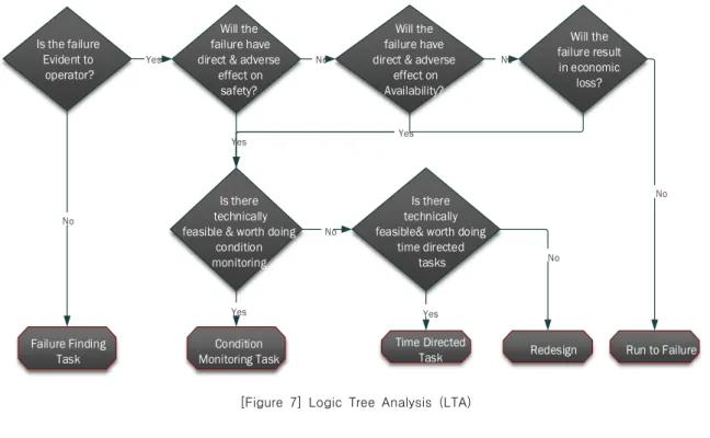
∙ Selection of the maintenance task using Logic Tree Analysis (LTA).

∙ Compare the new tasks with the current tasks and implementation of the process [2].

1.2 Objectives of the study

In this study RCM implementation process will be applied on the safety injection system for APR1400, the techniques of Functional Failure Mode Effects and Criticality Analysis (FME&CA) is applied to evaluate the different possible failure modes and the effect on com- ponent, system, and plant overall. Logic Tree Analysis (LTA) is used to determine the optimum maintenance tasks suitable for each failures modes according to the criticality class of each possible failure mode for the critical component.

2. Safety injection system

Safety Injection System is one of the engineered safety features (ESF) systems which provide protection in the highly unlikely event of an accidental release of radioactive fission products from the Reactor Coolant System (RCS), par- ticularly as the result of a Loss Of Coolant Accident (LOCA). The safety features function to localize, control, mitigate, and terminate such incidents and to hold exposure levels below applicable limits [3].

The safety injection system is comprised of four independent mechanical trains without any tie line among the injection paths and two electrical divisions. Each train has one active Safety Injection Pump (SIP) and one passive Safety Injection Tank (SIT) equipped with a Fluidic Device (FD). Figure 1 shows system arrangement, each train provides 50% of the minimum injection flow rate for breaks larger than the size of a direct vessel injection line.

For breaks equal to or smaller than the size of

a direct vessel injection line, each train has

100% of the required capacity. The low pressure

(3)

RCP: Reactor Coolant Pump, S/G: Steam Generator

RV: Reactor Vessel, IRWST: In containment Refueling Water Storage Tank

[Figure 1] Safety Injection system arrangement

injection pumps with common header installed in the conventional design are eliminated, and the functions for safety injection and shutdown cooling are separated [3-4].

3. Systems engineering process

Systems engineering process is a structured way of thinking about and defining a system.

The systems engineering process is an iterative approach to technical management, acquisition and supply, system design, product realization, and technical evaluation at each level of the system, beginning at the top (the system level) and propagating those processes through a series of steps which eventually lead to a preferred system solution [5].

3.1 Problem definition

The role of systems engineering is to define the problem correctly before seeking for solutions.

The functions of safety related systems should be maintained so that in the event of design

basis accidents, the provision of the mitigating functions would be assured. In preventive maintenance the failures are still likely to occur, the component may be over maintained, this leads to increase the interfaces with the component, in such unneeded maintenance there are chances of components incidental damage.

3.2 Problem solution

To increase the availability of the components and systems, the reliability centered maintenance is effective.

Because Condition Based Maintenance (CBM), focuses in system functions and use operation experience to analyze the failure modes effect and criticality analysis (FME&CA) techniques.

RCM can increase the condition monitoring tasks and reduce the system maintenance activities and interfaces to increase the availability and reliability of the system [2].

3.3 V-Model

V-model will be used in the Study execution because it ensures a maximum transparency for both project parties. It is a systematic approach to understand project requirements of the client and maps these requirements to process definitions. The V-model also performs reviews on multiple levels tracing all customer requirements through the entire project life cycle so as to ensure clear and unambiguous requirements. Figure 2 shows the V-Model that shall be used in the study [5].

3.3.1 Concept of Operation

In this step, stakeholders prepare the main-

tenance methodology that maintains the reliability

(4)

[Figure 2] the V-Model

of Safety Injection System (SIS). They reach a shared understanding of the system to be developed and how it will be operated and maintained. The concept of operations is documented to provide a foundation for more detailed analyses that will follow. It will be the basis for the system requirements that are developed in the next step.

3.3.2 System Operational Requirements The objectives of this step is to develop a validated set of requirements that meet the stakeholders’ needs, use of traditional time directed maintenance did not focus in the critical tasks and some important tasks have been ignored, the maintenance strategy re- quirements are:

∙ The maintenance strategy should increase the Mean Time To Failure (MTTF).

∙ The maintenance strategy should reduce the component failure rate.

∙ The maintenance strategy should maintain inherent component reliability.

∙ The maintenance strategy should increase components and systems availability.

∙ The maintenance strategy should reduce the maintenance cost.

∙ The maintenance strategy should increase the surveillance testing intervals.

∙ The maintenance strategy should reduce the system interfaces.

The operational requirements are evaluated

with control of the technical specifications of

the system of interest. The output is a set of

refined operational requirements which are

complete and consistent.

(5)

3.3.3 Functional Analysis

In this step, the possibility of developing a strategy that fulfills the operational objectives is evaluated. The systems engineers can use RCM studies and applications on the system of interest as a basis of evaluating the functions to be performed. Maintaining the plant safety is the most important factor to this process.

The operational objectives are translated into functional requirements. The functional requirements to be performed by RCM are:

∙ The maintenance strategy should maintain plant’s general safety.

∙ The maintenance strategy should optimize the maintenance activities.

∙ The maintenance strategy should maintain component and system reliability and availability when demanded.

∙ The maintenance strategy should achieve cost effectiveness.

3.3.4 System Design

In this step, system design is created based on the system requirements including a high- level design that defines the overall framework for the system. Subsystems of the system are identified and decomposed further into com- ponents. Requirements are allocated to the system components, and interfaces are specified in detail, produce a high-level design that meets the system requirements and defines key interfaces, that facilitates development, integration, and future maintenance and upgrades.

Previous steps in “V-model” have all focused primarily on defining the problem to be solved.

The system design step is the first step where we focus on the solution. This is an important transitional step that links the system requirements

that were defined in the previous step with system implementation that will be performed in the next step. The objective is to produce a high-level design that meets the system requirements and defines key interfaces, that facilitates development, integration, and future maintenance and upgrades.

Figure 3 shows the RCM process designed for SIS. The Work Breakdown Structure (WBS) and activities to be done during each phase are shown in the figure.

3.3.5 System Integration

In this step, the preparation of the new maintenance tasks selected for the critical components in the system are done. The objectives of this step are:

∙ Increase availability, reliability and safety of the system.

∙ Optimize the maintenance program.

3.3.6 System Verification

In this step, after system design is de- veloped based on the system requirements, assemble the system components into a working level and verify the requirements, the objectives of this step are:

∙ Integrate and verify the system in accordance with the high-level design requirements, verification plans and procedures

∙ Confirm that all interfaces have been correctly implemented

∙ Confirm that all requirements and constraints have been satisfied

3.3.7 System Validation

In this step, after the system has passed

system verification and is installed in the

(6)

[Figure 3] RCM process steps

operational environment, a regional agency, or another entity, runs its own set of tests to make sure that the deployed system meets the original needs identified in the concept of operations. After that installed the system and trained the users, and the customer has suc- cessfully conducted acceptance tests and formally accepted the system. In systems engineering, we draw a distinction between verification and validation. Verification confirms that a product meets its specified requirements. Validation confirms that the product fulfills its intended use.

4. Applying RCM for SIS

4.1 Function of Safety Injection System

∙ Injects borated water into the reactor vessel to assure adequate shutdown margin.

∙ Provides long-term post-accident cooling.

∙ Limits fuel damage to maintain coolable

core geometry.

∙ Removes the energy generated in the core and maintains the core subcritical after LOCA.

∙ Provide inventory make up and boration for reactivity control during safe shutdown, prevent boron perception in RCS during a long -term mode of system operation.

∙ Provide feed flow for feed- and-bleed operation in conjunction with pressurizer Pilot Operated Safety Relieve Valve (POSRV) to remove core decay heat during total loss of feed water to the steam generator [3-4].

4.2 System boundary

Selection and scoping of SSCs for SIS is further broken down into the following com- ponents:

∙ Safety Injection pump (SIP),

∙ Motor Operated Valve (MOV),

(7)

[Figure 4] Safety Injection System boundary

[Figure 5] Safety significant determination flowchart

∙ Check Valve (CV) and,

∙ Safety Injection Tank (SIT).

4.3 Data collection

∙ Design specifications.

∙ Operating experience from the operations staff.

∙ Probabilistic Safety Assessment results from PSA experts.

∙ Review of INPO (Institute of Nuclear Power Operations) and EPRI (Electric Power Research Institute) documentation.

∙ Maintenance history from maintenance personnel.

4.4 Component importance determination Using software (SAREX, KEPCO E&C) data to determine the safety significance of each component and identify the critical component.

SAREX is the computer software that can

conduct reliability analyses or probabilistic safety

assessments of industrial facilities including

nuclear power plants. Figure 5 shows the

flowchart used to determine safety significance

events and the critical component using the

(8)

Selecting Component

Non-Critical Critical

Preventive Proactive Condition Based

Monitoring Reactive

Selecting Component

Classifying Component

Task Selection

[Figure 6] Selection of Critical Component

<Table 1> Criticality classes Category Measure of

Criticality Criteria Unit Weight E 4.0-3.0 Effect on

Safety S 50%

F 3.0-2.0 Effect on

Availability A 30%

G 2.0-1 Effect on Maintenance

costs

C 20%

following parameters:

∙ Risk Reduction Worth (RRW).

∙ Risk Achievement Worth (RAW).

∙ Core Damage Frequency Contribution (CDFC).

The data from SAREX software for RRW, RAW, and CDFC used to identify the High Safety Significance (HSS) events and Low Safety Significance (LSS) events [6-7].

4.5 Critical items selection

The objective of this step, to identify the analysis items that are potentially critical with respect to the function of the system identified.

We should also identify items with high failure rate, high repair costs, low maintainability, long lead time for spare parts, or items requiring external maintenance personnel [8]. Safety injection pump, check valve, motor operator valve, and safety injection tank are selected as critical items.

Appendix (A) shows the highest risk significant component according to the PSA data.

4.6 Failure Mode Effect &Criticality Analysis (FME&CA)

Failure Mode Effect Analysis (FMEA) is a technique used to identify the potential functional failures and effects of those failures modes on

component, system, and plant performance. The consequences of each failure mode determine the type of maintenance tasks applied to prevent any degradation that can lead to failure [9].

For each failure mode there may be several failure root causes.

The failure mode effect analysis for the critical component which has the highest risk significant based on the PSA output data shown in appendixes:

∙ Appendix (B) for SIP.

∙ Appendix (C) for MOV.

∙ Appendix (D) for CV.

∙ Appendix (E) for SIT.

4.7 Criticality Analysis (CA)

The criticality analysis is based on the effects of the failure mode on the plant’s safety, availability and maintenance cost. The class ranges from E to G in the criticality analysis table 1 shows the criticality class. Criticality analysis for each failure mode for the critical components in SIS shown in appendixes:

∙ Appendix (B) for SIP.

∙ Appendix (C) for MOV.

∙ Appendix (D) for CV.

∙ Appendix (E) for SIT.

(9)

Is the failure Evident to operator?

Will the failure have direct & adverse

effect on safety?

Will the failure have direct & adverse

effect on Availability?

Will the failure result in economic

loss?

Is there technically feasible & worth doing

condition monitoring

Is there technically feasible& worth doing

time directed tasks

Failure Finding Task

Condition

Monitoring Task Time Directed Redesign Run to Failure

Task

No

Yes No No

Yes Yes

No

No

Yes Yes

No

[Figure 7] Logic Tree Analysis (LTA)

4.8 Task Selection (LTA)

This is the stage of the RCM process that allocates maintenance tasks to various failure modes identified based on the criticality analysis using Logic Tree Analysis (LTA), the logic diagram considers five major criteria as follow:

∙ Whether the failure is evident to the operator in the control room.

∙ Whether the failure has a direct effect on public or plant’s safety.

∙ Whether the failure poses a threat to component availability.

∙ Whether the failure results in a major economic loss.

∙ Whether the maintenance task to be selected is technically feasible and worth doing.

The maintenance tasks available for con- sideration are:

∙ Failure finding tasks: whose failure modes are hidden and require functional tests to

detect.

∙ Condition based tasks: tasks that monitor the degradation levels of failure modes.

∙ Time directed task: maintenance tasks performed periodically as scheduled.

∙ Re-design: where there is neither feasible condition directed nor time directed tasks applicable, and

∙ Run to failure: is applied on less safety and economical failure modes. Their failures are tolerable and corrective action is applied after failure.

Figure 7 shows the logic tree analysis flowchart which summarizes the process, and the output of this step is classified as:

∙ Retain: the new tasks exactly match the existing Preventive Maintenance (PM) tasks.

∙ Modify: the new tasks differ slightly in

context or frequency from the existing PM

tasks and will make these tasks more

(10)

applicable and effective.

∙ Delete: the new tasks may be replaced by more applicable and effective tasks.

∙ Add: the new tasks intended to prevent or mitigate identified failures for the com- ponents whose existing tasks do not provide this appropriately. Add new tasks apply to all of those components for which there are no existing PM tasks but RCM has identified applicable and effective tasks.

The selected tasks for each failure root cause related to the critical component shown in appendixes:

∙ Appendix (B) for SIP.

∙ Appendix (C) for MOV.

∙ Appendix (D) for CV.

∙ Appendix (E) for SIT.

5. Improve SIP availability and reliability

Unavailability of SIP due to extension of Surveillance Test Interval (STI) calculated from equation (1) [10].

[1]

Where:

Qtm: SIP unavailability due to test and maintenance

T1: (Surveillance test+ Overhaul Test) F: Testing frequency

Cycle time: Tow refueling periods

T2: Corrective maintenance time = (Downtime frequency x total cycle time x MTTR)

= 8.42x10⁻⁵/hx36x30x24hsx20.9hrs

=45.61hrs

Mean Time To Repair (MTTR) = 20.9 hours.

Based on the historical record of the SI pump operation and performance, the MTTR of the SI pumps in Ulchin power plant units is 20.9 hours [11]. Unavailability of the pump after extending the STI to six months will be (Qtm) = 0.0020679.

The reliability of SIP calculated from the equation (2) [12].

[2]

Where:

R (t): Reliability of the pump Qtm: Unavailability of the pump R (t) = 1- 0.0020679 = 99.793

The reliability of safety injection pump will be 99.793 % in two refueling periods.

Condition based Maintenance increases the operational availability of the SIP because of the increasing in the Mean Time To Failure (MTTF), as availability calculated from the equation (3).

[3]

Where MTTR is the Mean Time To Repair.

Extending the surveillance test interval would lead to an improved pump’s availability, eliminate unnecessary maintenance tasks, and optimize maintenance activities; the new surveillance test interval will be sex months.

6. Conclusions

RCM methodology is an effective approach

(11)

to optimize the maintenance activities and increase the availability and reliability of the components and systems. According to PSA data SIP, MOV, CV and SIT, are the major components in the SIS. The FME&CA carried out in this study investigated the possible failure modes for the major components in the system.

Application of RCM maintenance concluded that many of the current task types and task frequencies required revision in order to maintain the optimum levels of both availability and reliability of SIS. In several cases, specific components within the SIS will benefit from a shift in maintenance strategy from fixed interval to a CBM strategy. Such a strategy will ensure close monitoring of system and component performance without compromising nuclear safety or availability. It is recommended that the current SIS maintenance activities be reviewed and new PM tasks detailed in the tables adapted. After applying the RCM process 62.7% of the potential failures can be detected and prevented by CBM, 28.9% of failure can be detected and prevented by time based maintenance, 4.2% needs to redesign, 4.2% for failure finding and no run to fail for any failure modes. The number of CBM task increased this will reduce components failure rates, improve reliability and reduce run to fail components.

For SIP which is the main component in the SIS and its unavailability has a great contribution to system unavailability, the surveillance test interval can be extended from three months to six months and this will lead to decrease pump unavailability and maintenance and test cost will reduced as well.

Acknowledgements

The research was supported by the 2015 Research Fund of the KEPCO International Nuclear Graduate School (KINGS), Republic of Korea.

References

1. IAEA-TECDOC-1590 Application of Reliability Centered Maintenance to Optimize Operation and Maintenance in Nuclear Power Plants, May 2007.

2. Rausand M, Reliability centered maintenance Reliability Engineering and system Safety vol.60, pp2, 1998.

3. APR1400 Safety Analysis Report, (2004).

4. KHNP, “APR1400 Technical Specification”, (2010).

5. Alexander Kossiakoff, Systems Engineering Principles and practice 2nd Edition, John Willey& Sons Publishers, 57-159, 2011.

6. INPO, Equipment Reliability Process De- scription, INPO AP-913, Rev. 3, 2011.

7. EPRI, Preventive Maintenance Basis Database (PMBD), Ver. 5.1.1, 2004.

8. EPRI, Critical Component Identification Process - Licensee Examples, TR-1007935, 2003.

9. The basic concepts of failure analysis, Marvin Rausand & Knut Oien, Reliability Engineering and System Safety 53, January 1996.

10. Kim, Y. "Risk Informed Allowed Outage Time Change for Units 3&4" (2001).

11. KAERI/TR-1772, “Risk-Informed Allowed

Outage Time Change for Ulchin Units

3&4”, 2001.

(12)

12. Systems engineering approach to Reliability

Centered Maintenance of Containment Spray

Pump, Ohaga Eric Owino & Jung Jae Cheon,

and Lee Yong-Kwan. Journal of the Korea

Society of Systems Engineering vol.9,

June 2013.

(13)

<Appendix A> PSA Evaluation Results of SIS High Significant Components

Event

RAW RRW Failure probability

Significant RAW RAW >

2.00 RRW RRW >

1.005

Failure probability

90%

CDF

SICVWQ4V113/23/33/43 1.734E+03 Yes 1.024E+00 Yes 1.346E-05 No High

SIMVWQ4616/26/36/46 1.221E+02 Yes 1.022E+00 Yes 1.781E-04 No High

SISPP-S 1.593E+03 Yes 1.020E+00 Yes 1.250E-05 No High

SIOPH-S-HLI 3.679E+01 Yes 1.010E+00 Yes 2.760E-04 No High

SIMVWD2-321/331 3.679E+01 Yes 1.007E+00 Yes 2.044E-04 No High

SIMPWQ4-CSP1A/B/SCP1A/B 1.505E+01 Yes 1.002E+00 No 1.138E-04 No High

SIMVT1A-644 5.348E+00 Yes 1.001E+00 No 1.478E-04 No High

SICVO1A-V245 5.348E+00 Yes 1.001E+00 No 1.170E-04 No High

SICVO1B-V215 5.348E+00 Yes 1.001E+00 No 1.170E-04 No High

SIMPKQ2PP02C/D 3.699E+01 Yes 1.000E+00 No 5.793E-06 No High

SICVWQ3V540/41/43 5.226E+01 Yes 1.000E+00 No 2.855E-06 No High

SIMPWQ2PP02A/B 3.686E+01 Yes 1.000E+00 No 3.680E-06 No High

SICVWQ3V217/37/47 2.237E+01 Yes 1.000E+00 No 2.855E-06 No High

SICVWQ2-V434/46 3.695E+01 Yes 1.000E+00 No 1.685E-06 No High

SICVWQ4V215/25/35/45 5.348E+00 Yes 1.000E+00 No 1.346E-05 No High

SICVWQ3-V424/26/48 4.279E+01 Yes 1.000E+00 No 1.127E-06 No High

SIMPWQ3PP02A/B/D 4.278E+01 Yes 1.000E+00 No 1.067E-06 No High

SICVWQ3V113/23/33 1.464E+01 Yes 1.000E+00 No 2.855E-06 No High

SICVWQ4V568/569/1001/1002 1.494E+01 Yes 1.000E+00 No 2.621E-06 No High

SICVWQ2-V424/26 3.682E+01 Yes 1.000E+00 No 9.980E-07 No High

SICVWQ3V215/35/45 5.347E+00 Yes 1.000E+00 No 2.855E-06 No High

SITKB1A-SIT01A 5.347E+00 Yes 1.000E+00 No 2.042E-06 No High

SITKB1B-SIT01D 5.347E+00 Yes 1.000E+00 No 2.042E-06 No High

(14)

<Appendix B> Safety Injection Pump (FME&CA and task selection) [12]

Item Failure Root Cause Effect on system Criticality

class maintenance tasks

(proposed) Monitoring parameter

Bearing

Wear-fatigue-

age Loss of

Redundancy E Condition directed [vibration

analysis] Bearing casing vibration Wear-fatigue-

misalignment Low system flow E Condition directed [vibration analysis+ Airborne acoustic analysis]

Pressure Vibration Noise level Wear-fatigue-

excessive loading Loss of

Redundancy E Condition directed [vibration

analysis] Vibration

Flow Measurement Wear-fatigue-

personnel error Loss of

Redundancy E Failure Finding Check Personnel

training level Wear incorrect

lubricant Loss of

Redundancy E Condition directed

[Lubrication analysis] Measure oil bearing quality

Seal

Worn out seals Loss of

Redundancy E Condition directed [Airborne

acoustic analysis] Pressure Flow Wear of rotor

erosion Loss of

Redundancy E Condition directed [vibration

analysis] Measure loading+

vibration

Cracked Low system flow E

Condition directed [Vibration analysis+

Airborne acoustics, operator rounds]

Measure vibration acoustics

Shaft

Cracked Loss of

Redundancy E

Condition directed [Vibration analysis+

Airborne acoustics, operator rounds]

Measure vibration acoustics

Shaft wear Loss of

Redundancy E Condition directed [Vibration analysis+

Airborne Acoustics]

Measure vibration acoustics

Bend shaft Loss of

Redundancy E

Condition directed [Vibration analysis+

Airborne acoustics, operator rounds]

Measure vibration acoustics

Impeller

Vane thinning Low system flow E Condition directed [Vibration

analysis] Measure pump head

Wear vortexing Low system flow E Condition directed [Vibration

analysis] Measure impeller

vibration Loose or failed

key Loss of

Redundancy E Condition directed [Vibration

analysis Measure vibration

acoustics Damage by debris Loss of Redundancy E Re-design install strainer

Wear-cavitation Low system flow E Condition directed [Vibration

analysis] Measure pump flow

rate Face/shroud

rubbing Low system flow E Condition directed [Airborne

acoustic analysis] Measure impeller acoustic level

Cracked Blade Loss of

Redundancy E Condition directed[Vibration analysis+ Airborne

acoustics, operator rounds] Measure flow and head

(15)

<Appendix B> Continued.

Item Failure Root Cause Effect on system Criticality

class maintenance tasks

(proposed) Monitoring parameter

Motor Rotor

Loose lamination Low system flow E Condition directed [Infrared-Thermography+

Motor current signature]

Measure winding temperature

Failed rotor band/shorting rings

Loss of

Redundancy E Condition directed [Infrared-thermography+m

otor current signature]

Measure circuit resistance

Rotor/stator mechanical interface problem

Low system flow

E Condition directed [Infrared-thermography+vi

bration analysis]

Measure vibration acoustics

Loose retaining

rings Low system flow E Time directed [Scheduled restoration, general

inspection, Replace rings] Replace ring

Loose rotor cage Low system flow E Time directed [scheduled tightening, partial

disassembly, Replace cages] Replace cages Contaminated

laminations Low system flow E Failure Finding Flow

Winding insulation

degradation Loss of

Redundancy E Time directed [insulation diagnosis, partial

disassembly]

Measure winding temperature+ PI level Winding insulation

degradation from corona

Loss of

Redundancy E Time directed [insulation diagnosis, partial

disassembly]

Measure winding temperature

Loose blocking &

bracing Loss of

Redundancy E Time directed [Partial disassembly, general

inspection] Appearance

(16)

<Appendix C> Motor Operated Valve (FME&CA and task selection) Sub-comp

onent Failure mode Failure effect Criticality

Class maintenance tasks (proposed) Monitoring parameter Stem Stiffness of

stem movement

Does not close E Condition directed

[Infrared-Thermography + motor circuit analysis]

Monitoring of motor power and stem forces

Does not close E Time directed [Scheduled inspection and functional test, partial

disassembly, Scheduled cleaning and lubrication of stem]

Measure Stem Torque

Does not close E Condition directed [vibration analysis] Measurement of stem forces

Does not close E Condition directed [Lubrication

analysis] Measure oil quality

Breaking of

stem nut Does not close E Condition Monitoring

[Infrared-Thermography + motor circuit analysis]

Monitoring of stem forces and motor power

Does not close E Time directed [Scheduled inspection and functional test, partial

disassembly, Replacement of stem]

Measurement of stem forces

Torque

switch Wrong adjustment/set

ting

Does not close E Time directed [Scheduled inspection and functional test, partial

disassembly, Adjustment of torque switch]

Monitoring of torque switch tripping

Wrong operation Torque switch

Does not close E Condition directed [Vibration

analysis+ Airborne acoustics] Measurement of stem force

Does not close E Condition directed [vibration analysis] Monitoring of limit switch tripping.

Does not close E Redesign Change location

Limit

switch Wrong setting Does not close E Time directed [Scheduled inspection and functional test, partial

disassembly]

measurement and monitoring of limit switch tripping

Wear Does not close E Condition directed [vibration

analysis+ Airborne acoustic analysis] Measure loading+

vibration

Human factors Does not close E Failure finding Check personnel training level

Micro switch

Stiffness of

mechanism Does not open E Time directed [Scheduled inspection and functional test, partial

disassembly]

The measurement and monitoring of motor power Dirtiness of

contacts Does not open E Condition directed [Scheduled

cleaning, partial disassembly] Measurement of stem forces

Hand

drive Breaking of declutch lever

key

Does not open E Redesign Change declutch lever key

location Contactors Dirtiness and

oxidation of contacts

Does not open E Time directed [Scheduled servicing,

partial disassembly of contactors] Measure temperature of connections

Does not open E Condition directed

[Infrared-thermography] Measure circuit resistance Contactors Dirtiness and

oxidation of contacts

Does not open E Time directed [Scheduled servicing,

partial disassembly of contactors] Measure temperature of connections

Does not open E Condition directed

[Infrared-thermography] Measure circuit resistance Circuit

board for contactor relays

Electric component

fault

Does not open E Time directed [Scheduled inspection and functional test, partial

disassembly]

Measure temperature of connections

Does not open E Condition directed

[Infrared-thermography] Replacement if necessary

(17)

<Appendix D> Check Valve (FME&CA and task selection) Sub-compon

ent Failure mode Failure

Effect Criticality

Class Proposed Maintenance Task

(proposed) Monitoring Parameters Hanger pin Hanger pin

wear Does not

open E Condition directed [Radiography] Dimensions, Appearance and Roughness

Corrosion Does not

open E Time Directed [Scheduled inspection and functional test, lubrication Disassembly]

Dimensions, Appearance and Roughness

Fracture Does not

open E Time Directed Disassembly

Replacement] Dimensions, Appearance and

Roughness Hanger Pin

bearing Does not

close E Time Directed [Scheduled inspection and functional test, lubrication disassembly]

Dimensions, Appearance and Roughness

Wear Does not

close E Condition directed [Radiography] Dimensions, Appearance and Roughness

Seals External

Leakage Loss of

Function E Time Directed [Scheduled

inspection and Replacement] Appearance, Packing gland fitting

Oburator Wear Loss of

Function E Condition directed [Eddy Current

Magnetics] Dimensions Cracking,

Obturator-movement, Corrosion Loss of

Function E Time Directed [Scheduled

inspection and Replacement] Appearance Roughness Force or Torque

Hanger Wear Loss of

Function E Condition directed [Radiography] Dimensions, Appearance Corrosion Loss of

Function E Time Directed [Scheduled

inspection and Replacement] Appearance, Roughness Force or Torque Fracture Loss of

Function E Time Directed [Scheduled inspection and Replacement and functional test, disassembly, replace]

Appearance Roughness Cracking Spiral wound

Gasket Leaking Loss of

Function E Condition directed[Leak

monitoring] Appearance, Noise, packing

gland fitting

Cap Wear Loss of

Function E Condition directed [Leak

monitoring] Appearance, Dimension

Seat Wear Loss of

Function E Condition Monitoring [Back Flow

Test Ultrasonic Testing] Dimensions Appearance Roughness

Corrosion External

leakage F Time Directed [Scheduled

inspection and Replacement] Appearance, Roughness, Force or Torque Foreign

Materials External

leakage F Condition directed [Acoustics,

eddy Current] Appearance

(18)

<Appendix E> Safety Injection Tank (FME&CA and task selection) [3]

Item Failure

Mechanism Root Cause Effect on system Criticality

Class Maintenance task

(proposed) Monitoring parameter SIT

Discharge Isolation

Valves

Fails to Open Elect.

malfunction , mech. binding, contamination

No impact on performance of safety function

F Condition directed [vibration analysis+

Airborne acoustic analysis]

Valve position indicator

Fails to close Elect.

Malfunction, mech. binding, operator. error

Loss of flow from

one SIT

E Condition directed [Infrared Thermography +

motor circuit analysis]

Valve position indicator;

Periodic testing

SIT Fill and Drain Isolation

(Valves designed to fail

closed and is normally

closed)

Fails Open or fails To close

on SIAS

Elect.

Malfunction, seat failure, contamination

None F Condition directed

[vibration analysis+

Airborne acoustic analysis]

Valve position indicator

Fails

closed Airline separated from operator;

mech. binding

No impact on performance of safety function

E Condition directed [vibration analysis+

Airborne acoustic analysis]

Valve position indicator; SI

tank level SIT Fill Line

Isolation Valve normally closed and is designed to fail

closed

Fails open Or fails To close On SIAS

Elect.

malfunction, seat failure, contamination

None F Condition directed

[vibration analysis+

Airborne acoustic analysis]

Valve position indicator

Fails

closed Mech. binding, airline separates

from operator

No impact on performance of safety function

F Condition directed [vibration analysis+

Airborne acoustic analysis]

Valve position indicator; SI tank level indicator Nitrogen

Supply Valves (Valve is designed fail

closed)

Fails

closed Mech. binding, airline separated

from operator.

Cannot repressurize one

SI tank when required

E Condition directed [Vibration analysis, system engineer

walk down]

Valve position indicator.

Fails open Mech. binding, seat erosion,

Elect.

Malfunction.

None F Condition directed

[InfraredThermograp hy+ Motor current

signature]

Valve position indicator

SIT Wide range Level

indication Narrow(Provid e high and low

level alarms)

Fails to indicate correctly

Elect.

Malfunction, mech. failure

Inconsistent level indication between

SIT level indicators

F Condition directed [Vibration analysis, system engineer

walk down]

Level indicators in control room

SIT Wide Range Pressure Indicator(Provi

de high and low level

alarms)

Fails To indicate correctly

Elect.

malfunction Inconsistent level indication between

SIT level indicators

F Condition directed [Vibration analysis, system engineer

walk down]

Pressure indicators

control room in

수치

Figure  7  shows  the  logic  tree  analysis  flowchart  which  summarizes  the  process,  and  the  output  of  this  step  is  classified  as:

참조

관련 문서

The objective of this research is to propose a method for evaluating service reliability based on service processes using fuzzy failure mode effects analysis (FMEA) and grey

The objective of the present study is to determine the relationship between the types of children's character according to Murphy-Meisgeier Type Indicator

The study derived the problems according to results of field-centered synthetic analysis on yellow croakers of fishery system currently used in Chujado, Korea

In this way, it is possible to shorten the time of accident restoration and maintenance by minimizing the expression error of the high-strength facial

– A system or plant equipment list or P&amp;ID, knowledge of equipment function and failure modes, knowledge of system or plant function and response to equipment

□ The least-upper-bound property (sometimes called completeness or supremum property) is a fundamental property of the real number system. The least-upper-bound

To pray for the safety of each fisherman, the shaman walks around the edge of the boat, and offers sacrificial offerings to all the invited gods. The reason she walks around the

The “Asset Allocation” portfolio assumes the following weights: 25% in the S&amp;P 500, 10% in the Russell 2000, 15% in the MSCI EAFE, 5% in the MSCI EME, 25% in the