논문 15-41-01-04
The Journal of Korean Institute of Communications and Information Sciences '16-01 Vol.41 No.01 http://dx.doi.org/10.7840/kics.2015.41.1.37
이미지 센서 및 가시광 통신 기반 위치 추정 기술
Nam-Tuan Le
, Md. Shareef Ifthekhar
*, Ratan Kumar Mondal
*, Yeong Min Jang
°Localization Techniques Based on Image Sensor and Visible Light Communication
ABSTRACT
Localization is one of the key issues of demandable applications, especially smart services. Beside the traditional GPS based localization technique, the localization issue by visible light communications is promising market because of possibility of combining visible light communications with positioning technique for a high accurate, especially indoor localization service. This paper provides the overview and new image sensor scheme for localization issue based on visible light communication. The survey is introduced from core techniques to enhancement issues of localization. We hope these will be the essential references for the impact selection method in implementation and standardization issues.
Key Words : Visible light communication, Localization, AOA, TOA, RSSI, Cell-ID
※ This work was supported by Institute for Information &communications Technology Promotion (IITP) grant funded by the Korea Government (MSIP) (No. R0127-15-1025, Development of Optical Wireless Communications (OWC) Standardization).
First Author : Department of Electronics Engineering, Kookmin University, Seoul, Korea, [email protected], 학생회원
° Corresponding Author : Department of Electronics Engineering, Kookmin University, Seoul, Korea, [email protected], 종신회원
* Kookmin University, Seoul, Korea
논문번호:KICS2014-11-470, Received November 24, 2014; Revised December 6, 2015; Accepted January 15, 2016
Ⅰ. Introduction
There has been much research conducted on indoor localization technique during last several decades due to the possibility of diverse services for indoor navigation such as autonomous guided vehicles, specific product location in a shopping mall, car parking navigation system etc. For indoor localization, the research on localization utilizing visible light fixtures as positioning anchors has been considered strongly. This issue is a merger of visible light communication and positioning technique. It can be called as visible light communication positioning (VLCP). VLCP falls under the general category of indoor positioning systems (IPS) which is complementary to existing positioning technologies such as Wi-Fi, RFID, UWB and ultrasound. Typical
service cases include indoor navigation, tracking, autonomous robotics, mobile gaming, security, and location-based services (LBS).
It is commonly agree that the future wireless positioning systems will not be based upon a single technology; rather, these systems will encompass a number of different complementary technologies for hight accuracy. The core architecture behind VLCP is the overhead lighting fixtures as transmitters and the user‘s smart devices with camera or VLC interface as the receiver for the lightwave signal.
The main contribution of this paper shows the possibilities and characteristics of VLCP techniques for implementation properties. They include time of arrival (TOA), angle of arrival (AOA), time difference of arrival (TDOA), received signal strength indication (RSSI), cell identification
(Cell-ID) and a proposed technique based on image sensor.
The remaining of paper is structured as follows. In section II, published localization techniques and considerations are detail in VLCP implementation.
Section III presents a new issue of localization based image sensor. And section IV is the conclusion.
Ⅱ. Core Localization Techniques
Several types of localization techniques are being used for various location based services in different kinds of wireless networks[1]. For outdoor service, it is mostly based on GPS. However for indoor, GPS operates poorly. VLCP is a new solution for in door localization which operates as GPS system by using constellation of lights for the constellation of orbiting satellites. The technical classification for localization can be considered by the calculation, reference coordinator or signal transmission. However for critical consideration, it is the impact between one-way positioning and two-way positioning. A well-known one-way positioning technique is GPS.
The coordinate is processed locally by the GPS receiver device. In this technique the GPS receiver does not “talk back”. Another localization technique for one-way positioning is reference estimation technique. The estimation distance two targets is determined the relative to a given reference node.
RSSI is an typical example of this technique. With two-way positioning technique, it requires the interaction between reference node and target. It has limits system capacity and requires a supporting protocol; but can also provide hight accuracy. IEEE 802.15.4a is example of this technique. The synchronization packets are exchanged between devices in order to determine range.
2.1 Angle of Arrival (AOA) Method
In the AOA system, the location of the target can be determined by calculating the intersection of directional lines of bearing which formed within the spherical radius from a light’s transmitter to the mobile target in 3-D space. Each transmitter can self-transmit its position coordinates which allow the
receiver to interpret the source signal angle of arrival. The intersection of multiple signal source radials enables the receiver to estimate its position via triangulation. The advantage of AOA systems is no optical clock synchronization requirement between the light transmitters. So there is also no critical timing functions at the receiver. This technique is only really practical for VLCP when applying with an image sensor as typically associated with a camera. The disadvantage is poor accuracy when applying with high rates of mobility.
2.2 Time of Arrival (TOA) Method
The target estimation of TOA system based on the signal’s travel time. One of disadvantages of this technique is a completely network synchronization requirement. The distance from the object to a light transmitter is calculated by measuring the one-way propagation time. Geometrically, this distance defines a circular range around the transmitter light source. It requests at least three reference transmitters for determining the position which is given as the intersection of the range circles. As mentioned, the system has to be perfectly synchronized time stamp.
Then the receiver will ascertain the distance of the beacon signal which has traveled. With two-way round-trip methods, it can significantly reduce the error due to imperfect synchronization by transmitting an acknowledgement. TOA, when used with VLCP, will be difficult to implement due to the requirement of the relatively wide bandwidths to get sufficient time resolution, which are taxing for high brightness light sources.
2.3 Time Difference of Arrival (TDOA) Method
The TDOA approach is based on the relative position estimation of the user by monitoring the time difference at which the signals arrive from multiple light sources. It requests at least three lighting fixtures for 2-D positioning. The accuracy of method depends on the highly accurate clock synchronization between all light transmitters and the receiver. Similarly with TOA, the required bandwidths to achieve high accuracy will be the most
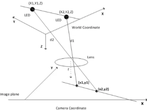
Fig. 1. Image sensor localization architecture
consideration because of high brightness condition oflight sources. Another approach which is related to TDOA is phase difference of arrival (PDOA). The multiple light sources are modulated with specific in-phase tones whose phase difference of arrival is detected at the receiver. Even though the required modulation bandwidth of the light source is relatively narrow, the operating frequencies for adequate performance are still charging the capabilities of a high brightness light.
2.4 RSSI-Based Method
RSSI (Received Signal Strength Indication) location estimation techniques measure the signal attenuation to calculate the signal propagation path loss, which is proportional to the distance between the user and transmitters. VLC RSSI positioning techniques require a line-of-sight propagation path to achieve high accuracy and the light transmitters must have a known radiance. There have several RSSI approaches such as path-loss model based algorithm, range-free algorithm, RSSI map-based algorithm, etc.
In general, RSSI techniques are difficult to implement with VLCP, partially because of angle of departure and angle of arrival dependent optical losses associated with the mobile device’s pose.
2.5 Cell-ID-Based Proximity Method
This is one of the simplest methods for estimating a object’s location. It works by using the proximity of a device with a given cell identification (Cell-ID).
In this method the position of the user is estimated based on the cell coverage information of the related overhead light transmitters. Each serving light transmits their own Cell-ID and the users infer their position by proximity. The accuracy of the positioning measurement depends on the serving cell coverage area. Cell-ID-based proximity can be thought of as a degenerate subset of AOA positioning.
2.6 Hybrid Methods
To improve the localization performance, methods may be combined to form hybrid methods. For example, the Cell-ID-based method may be combined
with other localization techniques to obtain more accurate positioning. When a mobile user gets a Cell-ID from two or more lights, a comparison of their signal strengths (i.e. RSSI method) can be made allowing the mobile user to decide which is the predominate serving cell. Another combination would be Cell-ID with AOA technique where each LED light transmitter can transmit its own coordinates through the ID and the receiver can use AOA techniques to calculate its actual coordinates.
Ⅲ. Imagine Sensor Localization
3.1 Architecture and Modeling
Beside traditional technique which based on signal processing issue, image sensor is another promising issue for localization in VLC system. By mapping image sensor coordinate with reference coordinate, we can estimate the location with high accuracy. The architecture of our scheme is shown by Figure 1.
This technique is a combination of visible light communication, camera communication, reference mapping technique and localization calculation.
The proposed system includes two steps. The first step is coordinate reference collection. Using camera communication technique[2] the receiver will define the coordinates of the reference light sources. Every LED will broadcast continuously its coordinates on optical channel. The architecture of transmitter is shown by Figure 2. Digital bit are modulated at different frequency which can pass the requirement
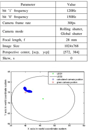
Parameter Value
bit '1' frequency 120Hz
bit '0' frequency 150Hz
Camera frame rate 30fps
Camera mode Rolling shutter,
Global shutter
Focal length, f 28 mm
Image Size 1024x768
Perspective center, [xcp, ycp] [572, 384]
Skew, s 0
Table 1. Implementation configuration
Fig. 3. Effect of Slope Angle
of eye frequency response[2]. The modulation is anoptional requirement, it can be OOK modulation.
However with indoor application it will be refer for a frequency shift OOK. The second step is coordinate estimation based on geometric and triangle calculation. The image sensor from camera captures the picture of the installed light source which is parallel to the both real coordinate XY plane and camera coordinate xy plane. From the reference coordinates information which is collected in first step, we can calculate the slope angle of connecting line from two LEDs and real plane coordinate system based on the information of focus lens. Similarly the slop angle of them on image plane also can calculate.
From these, we can establish a relationship between the angle difference between x axis of camera coordinate and X axis of real coordinate system by a linear rotation vector. The rotation vector and collinearity equation for location estimation are proven by mapping equation[3].
Fig. 2. CamCom architecture
3.2 Performance EvaluationThe performance evaluation of proposed system is based on simulation with various distance and
rotation angle. The system parameters are set up as following parameters in Table 1
As we have explained in theory that we calculate camera position according to the slope angle between two LEDs, so it is required to testified our algorithm for different slope of LEDs. Figure 3 shows the effect of slope angle. Here red circle represent the original camera position and blue one is calculated camera position. Green point indicates the position of LED 1 and we rotate the LED 2 position around the LED 1. Thus each position of LED 1 and LED 2 create different slope. And for each slope we calculated the camera position and blue one shows the result. According to the fig slop has some effect on our calculation as a result each time the calculated position is not exactly the same. However all calculated points for different slop are close to each other also close to the original camera position.
Hence the graphical representation of all calculated camera position for different slope create dense
butterfly like shape as shown in Figure 3.
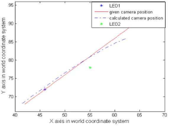
We also examine the effect of distance from two LEDs in Figure 4. Here blue and green point indicates the position of LED 1 and LED 2 respectively and we change the camera position describe in a path shown as red line. For each camera position we calculated the camera position according to our algorithm as shown in blue dotted one. According to the fig calculated camera position start deviate after passing LED 2.
Fig. 4. Effect of distance
Ⅳ. Conclusion
In this paper several positioning techniques were discussed for VLCP implementation. The survey can close the gap and foster the discussion on current status of localization technique in VLC.
References
[1] M. Yoshino, S. Haruyama, and M. Nakagawa,
“High-accuracy positioning system using visible LED lights and image sensor,” in Proc.
IEEE Radio and Wireless Symp., pp. 439-442,
Orlando, Florida, Jan. 2008.[2] R. D. Roberts, “Space-time forward error correction for dimmable undersampled frequency shift ON-OFF keying camera communications (CamCom),” ICUFN 2013, pp.
459-464, Da Nang, Jul. 2013.
[3] M. S. Ifthekhar, R. K. Mondal, N.-T. Le, and
Y. M. Jang, “Simple method for indoor localization in OCC using smart phone image sensor,” ICUFN 2014, pp. 55-58, Shanghai, Jul. 2014.