Journal of the Korea Institute of Building Construction, Vol. 12, No. 3
http://dx.doi.org/10.5345/JKIBC.2012.12.3.291 www.jkibc.org
Development of Efficient Curing Sheet
for Thermal‐Insulation Curing of Concrete in Cold Weather
Han, Cheon-Goo
1Son, Myung-Sik
2Choi, Hyun-Kyu
1*Department of Architectural Engineering, Cheongju University, Cheongju, 360-764, Korea
1Construction Headquarters, Samsung Medical Center, Gangnam-gu, Seoul, Korea 235-710, Korea
21)Abstract
For cold weather concreting, frost damage at early age is generated in the concrete, and problems such as delaying of setting and hardening and lowering of strength manifestation emerge due to the low outside air temperature at the early stage of pouring, making the selection of an effective curing method critically important. Unfortunately, the tent sheet currently used as the curing film for heating insulation at work sites, not only has the problems of inferior permeability and extremely deteriorated airtightness, but a phenomenon of continuous fracturing is also generated along the direction of fabric of the material itself, presenting difficult circumstances for maintaining adequate curing temperature. The aim of this study was to develop an improved bubble sheet type curing film for heating insulation of cold weather concrete by combining mesh-tarpaulin, which has excellent tension properties, with bubble sheet, which offers superior insulation performance. The analysis showed that the improved curing film in which BBS1 is stacked to MT was a suitable replacement for curing films currently in use, as it has better permeability, tension property, and insulation performance than the T type film used at work sites today.
Keywords : cold weather concrete, bubble sheet, mesh-tarpaulin, blue sheet, tensile strength, thermal conductivity
1. Introduction
With the number of high-rise, large and complex buildings on the rise, a great deal of time pressure is being placed on builders, and thus year-round methods of construction have been widely adopted, with a high level of interest emerging in cold weather concreting[1].
Cold weather concreting is when concrete is poured during cold weather, which brings the risk of freezing during curing. When concrete is placed in
Received : January 3, 2012 Revision received : March 8, 2012 Accepted : April 13, 2012
* Corresponding author : Choi, Hyun-Kyu
[Tel: 82-043-229-8480 E-mail : [email protected]]
ⓒ2012 The Korea Institute of Building Construction, All rights reserved.
cold weather, initial frost damage occurs to the concrete, and the strength development is affected by the retardation of concrete setting and hardening.
A combination of heating-insulation curing using a heater and insulation is recommended as the standard method.
Although the heating-insulation curing method is used on many construction sites because a tent is set outside the building to maintain the curing temperature using a heater, the tent material used as the curing insulation has a high heat loss coefficient, which means that its permeability is inferior and its air-tightness is deteriorated, and moreover the tent sheet is easily torn in the weave direction and a large amount of heat is also lost.
For these reasons, it is difficult to maintain the
curing room temperature at a certain level[2,3,4,5].
weather curing, and have suggested approaches such as the use of accelerators for freezing resistance, improvement of form performance, and a curing method using heating cables. There have been few previous studies on the sue of bubble sheet for curing for cold weather.
A thermal insulation curing film was thus developed using a combination of a bubble sheet with good insulation and Mesh-tarpaulin with good tension in order to replace the conventional tent material used as the thermal insulation curing film for cold weather curing on construction sites, and to verify its applicability, focusing on the development process and the test results.
2. Experimental plan and method
2.1 Experimental plan
The experimental plan for this study is shown in Table 1. It was designed for Series 1 to perform tensile and insulation tests on a total of 9 different specimens, including 3 types of blue sheets used for thermal insulation curing film in construction sites (tent sheet; hereinafter T), 1-, 2-, and 3-layered bubble sheets proven to be good for thermal insulation and keeping warm {bubble sheet: a material made to minimize the thermal conductivity ratio by forming an independent air foam layer for which air cap is combined with the PE film;
hereinafter BBS}, a Mesh-tarpaulin (hereinafter MT) made of polyethylene (hereinafter PE), a curing film made by combining one-layered bubble sheet with a sheet of MT (hereinafter MT+BBS1), and a curing film made by putting a one-layered bubble sheet between two sheets of MT (hereinafter MT+BBS1+MT).
When the curing film for thermal insulation and keeping warm in cold weather is used on a
Section Test level
Series 1
Factors Test
piece 9
· T
1)A, TB, TC
· MT
2)· BBS
3)1, BBS2, BBS3
· MT+BBS1
· MT+BBS1+MT Experiment 3 · Thickness-Weight
· Stress-strain curve
· Thermal conductivity
Series 2
Factors
piece Test 4
· MT · BBS1
· MT+BBS1
· MT+BBS1+MT Edge distance
(mm) 4 · 10, 15, 20, 25
Experiment 1 · Stress-strain curve 1) T : Blue sheets(Tent sheets)
2) MT : Mesh-tarpaulin 3) BBS : Bubble sheets
construction site, a certain level of tension at the connection part should be secured, since the entire structure should be cured at once. Therefore, in Series 2 the tension was tested depending on the edge distance for the specimens proven to be optimal in Series 1.
2.2 Experimental materials
As the thermal insulation curing film, three representative types of tent sheet, BBS made of PE resin and MT manufactured at Company J located in Chungju, Chungcheongbuk-do were used in the experiment.
2.3 Experimental Method
As the tensile test of this experiment is a
mechanical properties test, specimens were first
manufactured according to KS M 3001 to conduct a
tensile test as shown in Figure 1. The thermal
conductivity test is for the insulation material, and
the specimens were manufactured to be 300 mm ×
300 mm in size based on KS L 9016 as shown in
Figure 2, and then tested.
Journal of the Korea Institute of Building Construction, Vol. 12, No. 3
http://dx.doi.org/10.5345/JKIBC.2012.12.3.291 www.jkibc.org
Figure 1. Testing methods for mechanical characteristics of polyethylene film (KS M 3001)[8]
Figure 2. Testing methods for thermal transmission properties of thermal insulations (KS L 9016)[9]
1) Edge distance - 10 mm
2) Edge distance - 15 mm
3) Edge distance - 20 mm
4) Edge distance - 25 mm
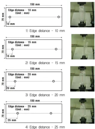
Figure 3. Method of tensile test depending on edge distance
In addition, a specimen with a size of 70 mm × 150 mm was manufactured for Series 2 as shown in Figure 3. The tensile test was performed at 4 different edge distances of eyelet, 10 mm, 15 mm, 20 mm and 35 mm.
3. Experimental results and analysis
3.1 Series 1
3.1.1 Properties characteristics of raw material of the curing film
Table 2 indicates the properties of the curing film measured using the specimen cut to 1,000 mm × 1,000 mm.
First, in terms of thickness, T type was measured as 0.18~0.22 mm thick, which is relatively thin, while MT was 0.55 mm thick. BBS type was measured to be 1.5~4.3 mm thick, while the MT+BBS1 and MT+BBS1+MT to be developed measured to be 2.03~2.05 mm thick, which is thicker than the existing T type. This result may be caused by the air in the independent air foam layer of BBS.
In terms of weight, T type was measured as 81.11~152.44 g/m 2 while BBS type was 80.56~232.22 g/m 2. However, MT+BBS1 and MT+BBS1+MT were measured as 268.33~349.44 g/m 2 , which is weightier than other specimens. From this it can be analyzed that the weight of MT was 189.00 g/m 2 , which is significantly heavier than the first, and as the MT was layered on the BBS1, the weight was proportionally increased.
Table 2. Physical properties of test piece
Test piece Size
(mm
2) Thickness
(mm) Weight
(g/m
2) Bubble size (mm) TA
1,000
× 1,000
0.22 152.44 -
TB 0.20 117.33 -
TC 0.18 81.11 -
BBS1 1.50 80.56 7
BBS2 2.90 159.67 7
BBS3 4.30 232.22 7
MT 0.55 189.00 -
MT+BBS1 2.03 268.33 7
MT+BBS1+MT 2.60 349.44 7
0 10 20 30 40 50 60 70 80 90 100 0
20 40 60 80 100 120 140 160 180 200 220 240
TA-1 TA-2 TA-3
Tensile stress (N)
Strain(mm)
0 10 20 30 40 50 60 70 80 90 100
0 20 40 60 80 100 120 140 160 180 200 220 240
TB-1 TB-2 TB-3
Tensile stress (N)
Strain(mm)
0 10 20 30 40 50 60 70 80 90 100
0 20 40 60 80 100 120 140 160 180 200 220 240
Strain(mm)
TC-1 TC-2 TC-3
Tensile stress (N)Tensile stress (N)
(a) TA (b) TB (c) TC
0 10 20 30 40 50 60 70 80 90 100
0 20 40 60 80 100 120 140 160 180 200 220 240
Strain(mm)
Tensile stress (N)
BBS1-1 BBS1-2 BBS1-3
0 10 20 30 40 50 60 70 80 90 100
0 20 40 60 80 100 120 140 160 180 200 220 240
Strain(mm)
Tensile stress (N)
BBS2-1 BBS2-2 BBS2-3
0 10 20 30 40 50 60 70 80 90 100
0 20 40 60 80 100 120 140 160 180 200 220 240
Tensile stress (N)
Strain(mm)
BBS3-1 BBS3-2 BBS3-3
(d) BBS1 (e) BBS2 (f) BBS3
0 10 20 30 40 50 60 70 80 90 100
0 20 40 60 80 100 120 140 160 180 200 220 240
Tensile stress (N)
MT-1 MT-2 MT-3
Strain(mm)
0 10 20 30 40 50 60 70 80 90 100
0 20 40 60 80 100 120 140 160 180 200 220 240
Strain(mm)
Tensile stress (N)
MT+BBS1-1 MT+BBS1-2 MT+BBS1-3
0 10 20 30 40 50 60 70 80 90 100
0 20 40 60 80 100 120 140 160 180 200 220 240
Tensile stress (N)
Strain(mm)
MT+BBS1+MT-1 MT+BBS1+MT-2 MT+BBS1+MT-3
(g) MT (h) MT+BBS1 (j) MT+BBS1+MT
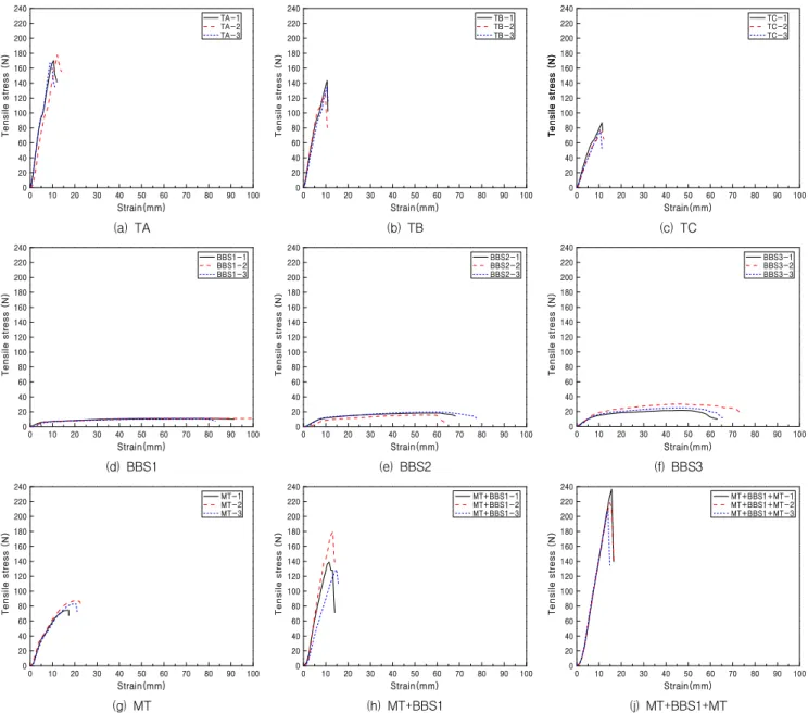
Figure 4. Stress-strain curve depending on basic raw materials
Figure 4 shows stress-strain curves from three tests of the raw materials for the thermal insulation curing film for cold weather. First, the ultimate tensile stress of TA was shown to be 170 N, which was also highest among T type, followed by 140 N to TB and 77 N to TC. The thicker the materials, the higher the tensile stress. The strain against the ultimate tensile stress of T was similarly shown at around 10 mm.
However, the ultimate tensile stress of the bubble
measured to be 11 N to BBS1, 18 N to BBS2 and
25 N to BBS3. Although they were thicker than T,
there were big differences in tensile stress
compared with those of T. It is believed that unlike
T made of PVC in the grid form, the tensile stress
of BBS was lower because it was made of PE resin,
and the space of the air foam layer may cause the
stress to be much lower. However, the strain of
BBS type was shown to be the highest in the entire
section due to its high malleability, as illustrated in
Journal of the Korea Institute of Building Construction, Vol. 12, No. 3
http://dx.doi.org/10.5345/JKIBC.2012.12.3.291 www.jkibc.org
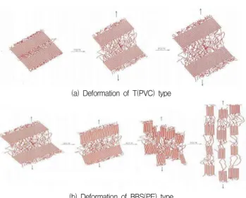
(a) Deformation of T(PVC) type
(b) Deformation of BBS(PE) type
Figure 5. Deformation of test piece (T type and BBS type)
Figure 5, PE resin consists of chains of high polymers. When tensile stress is applied, its chain axis becomes oriented parallel to the tensile axis, reinforcing the direction locally and causing resistance to prevent continual deformation. For this reason, it is analyzed that strain was increased when similar stress was put at the yield point.
The ultimate tensile stress of MT was measured to be 82 N, at which the strain was 20 mm. MT, though made of the same raw material with PE resin as BBS, had a higher tensile stress because it was reinforced by the grid form.
The ultimate tensile stress of MT+BBS1, the curing film being developed in this research, was measured to be 143 N, at which the strain was about 11 mm. The ultimate tensile stress of MT+
BBS1+MT was measured to be 220 N, the highest among the specimens, at which the strain was about 17 mm. The increase in the strain is believed to have been reinforced by MT with the grid form layered on BBS1.
Figure 6 indicates the ratio of the ultimate tensile strength to tensile strength by specimen. MT+
BBS1, the curing film to be developed in this research, was used as the standard for comparison.
First, the tensile stress ratio of MT+BBS1+MT was shown to be 58% and 22% higher than those
T1 T2 T3 BBS1 BBS2 BBS3 MT MT+BBS1 MT+BBS1+MT
0 20 40 60 80 100 120 140 160 180 200 220 240 260
Tensile force ratio (%)
Tensile force (N)
Test piece
0 20 40 60 80 100 120 140 160 180
Figure 6. Tensile strength ratio of basic raw materials
of MT+BBS1 and TA, respectively, which are currently evaluated as the best tent sheets. In addition, the tensile stress ratio of MT+BBS1 was 3% higher than that of TB, but was overall similar to that of TB. However, the tensile stress of the remaining specimens was shown to be lower than that of MT+BBS1.
3.1.3 Insulation performance
Figure 7 shows the thermal conductivity ratio to basic raw materials. The thermal conductivity of T type currently used as the curing film was 0.25-0.27 W/m・K, which is highest of all specimens. The thermal conductivity of BBS type was 0.07 W/m・K, which was relatively low.
On the other hand, the thermal conductivity of MT+BBS1 and MT+BBS1+MT to be developed in this research was shown to be 0.05 W/m・K, the lowest of all. It is believed that BBS, with the independent air foam layer, reduced thermal convention, and the thermal conductivity became the lowest.
T1 T2 T3 BBS1 BBS2 BBS3 MP MP+BBS1 MP+BBS1+MP
0.00 0.05 0.10 0.15 0.20 0.25 0.30
Thermal conductivity (W/m·K)
Test piece
0 100 200 300 400 500
Thermal conductivity ratio(%)
Figure 7. Thermal conductivity of basic raw materials
0 20 40 60 80 100 120 140 160 180 200 40
80 120 160 200 240 280 320
BBS1-1 BBS1-2 BBS1-3 Edge distance 10 mm
Tensile stress (N)
Strain(mm)
0 20 40 60 80 100 120 140 160 180 200 40
80 120 160 200 240 280 320
MT-1 MT-2 MT-3
Tensile stress (N)
Strain(mm)
Edge distance 10 mm
0 20 40 60 80 100 120 140 160 180 200 40
80 120 160 200 240 280 320
MT+BBS1-1 MT+BBS1-2 MT+BBS1-3
Tensile stress (N)
Strain(mm)
Edge distance 10 mm
0 20 40 60 80 100 120 140 160 180 200 40
80 120 160 200 240 280 320
MT+BBS1+MT-1 MT+BBS1+MT-2 MT+BBS1+MT-3
Tensile stress (N)
Strain(mm)
Edge distance 10 mm
1) BBS1 - 10 mm 2) MT - 10 mm 3) MT+BBS1 - 10 mm 4) MT+BBS1+MT - 10 mm
0 20 40 60 80 100 120 140 160 180 200 40
80 120 160 200 240 280 320
BBS1-1 BBS1-2 BBS1-3 Edge distance 15 mm
Tensile stress (N)
Strain(mm)
0 20 40 60 80 100 120 140 160 180 200 40
80 120 160 200 240 280 320
MT-1 MT-2 MT-3
Tensile stress (N)
Strain(mm)
Edge distance 15 mm
0 20 40 60 80 100 120 140 160 180 200 40
80 120 160 200 240 280 320
MT+BBS1-1 MT+BBS1-2 MT+BBS1-3
Tensile stress (N)
Strain(mm)
Edge distance 15 mm
0 20 40 60 80 100 120 140 160 180 200 40
80 120 160 200 240 280 320
MT+BBS1+MT-1 MT+BBS1+MT-2 MT+BBS1+MT-3
Tensile stress (N)
Strain(mm)
Edge distance 15 mm
5) BBS1-15 mm 6) MT - 15 mm 7) MT+BBS1 - 15 mm 8) MT+BBS1+MT - 15 mm
0 20 40 60 80 100 120 140 160 180 200 40
80 120 160 200 240 280 320
BBS1-1 BBS1-2 BBS1-3 Edge distance 20 mm
Tensile stress (N)
Strain(mm)
0 20 40 60 80 100 120 140 160 180 200 40
80 120 160 200 240 280 320
MT-1 MT-2 MT-3
Tensile stress (N)
Strain(mm)
Edge distance 20 mm
0 20 40 60 80 100 120 140 160 180 200 40
80 120 160 200 240 280 320
MT+BBS1-1 MT+BBS1-2 MT+BBS1-3
Tensile stress (N)
Strain(mm)
Edge distance 20 mm
0 20 40 60 80 100 120 140 160 180 200 40
80 120 160 200 240 280 320
MT+BBS1+MT-1 MT+BBS1+MT-2 MT+BBS1+MT-3
Tensile stress (N)
Strain(mm)
Edge distance 20 mm
9) BBS1-20 mm 10) MT - 20 mm 11) MT+BBS1 - 20 mm 12) MT+BBS1+MT - 20 mm
0 20 40 60 80 100 120 140 160 180 200 40
80 120 160 200 240 280 320
BBS1-1 BBS1-2 BBS1-3 Edge distance 25 mm
Tensile stress (N)
Strain(mm)
0 20 40 60 80 100 120 140 160 180 200 40
80 120 160 200 240 280 320
MT-1 MT-2 MT-3
Tensile stress (N)
Strain(mm)
Edge distance 25 mm
0 20 40 60 80 100 120 140 160 180 200 40
80 120 160 200 240 280 320
MT+BBS1-1 MT+BBS1-2 MT+BBS1-3
Tensile stress (N)
Strain(mm)
Edge distance 25 mm
0 20 40 60 80 100 120 140 160 180 200 40
80 120 160 200 240 280 320
MT+BBS1+MT-1 MT+BBS1+MT-2 MT+BBS1+MT-3
Tensile stress (N)
Strain(mm)
Edge distance 25 mm
13) BBS1-25 mm 14) MT - 25 mm 15) MT+BBS1 - 25 mm 16) MT+BBS1+MT - 25 mm
Figure 8. Stress-strain curve depending on edge distance
Journal of the Korea Institute of Building Construction, Vol. 12, No. 3
http://dx.doi.org/10.5345/JKIBC.2012.12.3.291 www.jkibc.org
3.2 Series 2
When the thermal insulation curing film is set in a construction site, the concrete should be placed after covering the entire section of the structure to be cured. For this reason, a certain level of tension of the curing film is required for connection, and the tensile strength depending on the edge distance was evaluated in Series 2. However, the analysis of the edge distance was only conducted for the raw material of curing film to be developed.
Figure 8 is the tensile strength ratio depending on edge distance of the eyelet measured from three tests, and Figure 9 is the ultimate tensile stress depending on edge distance by specimen.
It is a logical consequence that the farther the edge distance, the higher the tensile stress.
Meanwhile, the tensile stress of BBS1 was shown to be 39 N and 54N at 10 mm and 25 mm, respectively, which were lowest of all specimens.
The tensile stress of MT was measured as 118 N and 189 N at 10 mm and 25 mm, respectively, 3.5-4 times higher than that of BBS1. The tensile stress of MT+BBS1 to be developed was measured to be 127 N and 255 N at 10 mm and 25 mm, respectively, which was similar to but slightly higher than that of MT. The tensile stress of MT+BBS1+MT was measured to be 210 N and 295 N at 10 mm and 25 mm, respectively, which was highest of all. This is because of the high tensile stress reinforced by the grid form of MT.
As a result, it is revealed that when fixed to a neighboring curing film or a pipe scaffolding, MT+BBS1 and MT+BBS1+MT can secure the strength of the material if the edge distance is set to be higher than 15 mm. If the edge distance and interval are determined in consideration of weight including design wind velocity, the design may be proven as effective.
10 15 20 25
0 40 80 120 160 200 240 280
320 BBS1
MT MT+BBS1 MT+BBS1+MT