35
1) 전남대학교 에너지자원공학과 2) 두산건설 토목환경BG 설계팀 3) 한국광물자원공사 기술기획팀
* 교신저자: [email protected] 접수일 : 2018년 12월 4일 심사 완료일 : 2018년 12월 11일 게재 승인일 : 2018년 12월 26일
화약발파에서 폴리머 겔의 전색효과에 관한 실험적 및 수치해석적 연구
Khaqan Baluch, 김정규, 고영훈, 김승준,
정승원, 양형식
*, 김용기, 김종관
Abstract In this study, several concrete-block blast tests and AUTODYN numerical analyses were conducted to analyze the effects of different stemming and coupling materials on explosion results. Air, sand, and polymer gel were used as both the stemming and coupling materials. The stemming and coupling effects of these materials were compared with those of the full-charge condition. Soil-covered or buried concrete blocks were used for field crater tests. It was found from the concrete block tests and numerical analyses that both the crater size and the peak pressure around the blast hole were higher when the polymer gel was used than when the sand and the decoupling condition were used. The numerical analyses revealed the same trend as those of the field tests.
Pressure peaks in concrete block models were calculated to be 37, 30, and 16 MPa, respectively, for the cases of the polymer gel, sand, and no stemming and decoupling condition. The pressure peak was 52 MPa in the case of full-charge condition, which was the highest pressure. But the damage area for the case was smaller than that obtained from the use of polymer gel. Full-charge was also used as a reference test.
Key words AUTODYN, numerical analysis, coupling material, polymer gel, buried concrete block test 초 록 본 연구에서는 콘크리트 블록발파 실험과 AUTODYN 수치해석을 통해 몇 가지 전색제 및 충전재가 폭발결 과에 미치는 효과를 분석하였다. 전색제와 충전재는 공기, 모래, 폴리머 겔을 이용하였다. 이들 재료들의 전색효과 및 충전효과는 밀장전 조건의 경우와 비교하였다. 매립된 콘크리트 블록을 사용하여 현장 누두공 시험을 실시하였 다. 콘크리트 블록 실험 및 수치해석 결과 폴리머 겔을 사용한 경우가 모래 및 디커플링의 경우에 비해 누두공의 크기와 발파공 주위의 최대압력이 더 크게 나타나는 것을 확인하였다. 또한, 수치해석 결과는 현장시험 결과와 잘
일치하는 경향을 보여주었다. 주변암반 중에서 계산된 최대압력은 폴리머 겔, 모래, 무전색 및 디커플링 조건일 때 각각 37, 30, 16 MPa로 나타났다. 수치해석 모델 내 밀장전 시 최대 압력은 52 MPa로 가장 높게 나타났다. 그러나 손상영역의 크기는 폴리머 겔을 사용한 경우보다 작게 나타났다. 또한, 밀장전은 기준 실험으로 사용되었다.
핵심어 AUTODYN, 수치해석, 충전재, 폴리머 겔, 매립 콘크리트 블록 실험
1. Introduction
A stemming material helps to maintain high impact pressure in a blast hole, and thereby improves the fragmentation of rock mass. While it is effective to load a blast hole tightly, the packaging of explosives and the density of loaded charge may prevent tight loading. If an appropriate stemming material is used as a coupling material, it is expected that a higher pressure will be generated owing to the volume of the narrower blast hole, and more pressure will transmit to the surrounding rock mass. Therefore, a blasting with an appropriate stemming material will be more effective and thus reduce blasting costs in the end (Ko et al., 2017).
In general, water is considered as an efficient stemming and coupling material that can be used inside a blast hole. Zhu et al. (2008) performed a numerical study to analyze the effects of using water, sand, and air as stemming and coupling materials that are filled in between the explosive column and the inner wall of a blast hole under dynamic load conditions. They concluded that water created the largest fracture area by transferring shock waves efficiently to the surrounding rock mass. At that moment, reflected shock waves and the bubble pulses caused by the presence of water impose an extremely large load on the blasthole wall and increase the deformation and displacement of the rock mass.
Expanding water can generate air overpressure, and its energy is transferred to rock mass so that fractures and cracks are generated. This is followed by a high-pressure water vapor being released to the
cracks and contributing to crack extension (Bohloli et al., 2001).
Even if water is an excellent coupling material, it is difficult to stem the blast hole with water especially in the case of horizontal blast holes in tunnel rounds. In this study, a polymer gel was selected as the stemming and coupling material instead of water because it not only can maintain its shape but also is an excellent medium for transferring shock waves to the surrounding media. The polymer gel is an environment-friendly and non-toxic material and absorbs water quickly as soon as it gets dry (Dai et al., 2013; Ahmed et al., 2013). The polymer gel sells for only 200$/20kg, and 5 g of the polymer powder mixed with water will be sufficient for stemming 50 blasting holes of depth 1.5 m. A small amount of the polymer powder can swell to a larger volume of a gel having 99 wt% of water (Dabhi et al., 2013).
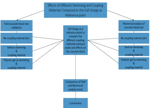
In this study, the effects of different stemming and coupling materials in a blast hole were investigated by conducting both the soil-covered or buried concrete-block blasting tests and numerical analyses on AUTODYN (Fig. 1).
2. Field tests
2.1 Construction of buried concrete blocks
To prevent excessive fragmentation due to the
explosion, several curing concrete blocks were buried
into the ground (soil) to a depth of 0.5 m for crater
tests. The diameter of the block was 2.0 m and the
thickness was 0.5 m, which was the same as the
(a) Block Design (b) Concrete Pouring
(c) Ground Soil Cover (d) Blast Hole Diameter Fig. 2. Typical crater test for concrete block.
Fig. 1. Flow diagram showing the methodology adopted in the study.
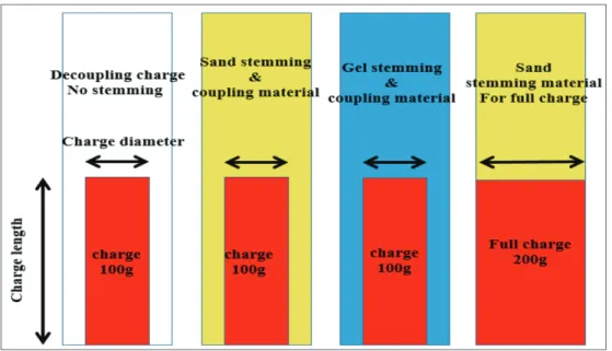
buried depth. The depth and diameter of the blast hole drilled at the center of each block were 0.25 m and 0.05 m, respectively, as shown in Fig. 2. Detailed charging conditions for the tests are given in Fig. 3.
2.2 Test results and discussions
The explosive material used in the test was an ordinary emulsion explosive with the weight of 100 g and the diameter of 32 mm. In the case of the full-charge test, the charge weight was 200 g, which played the part of the reference weight.
In general, when there is only a single free surface, namely in the case of crater test, the ratio between the radius (R) and depth (W) of the crater is referred to as the crater index, n. It is considered as the standard charge if the crater index is found to be n
= 1, an over charge if n > 1, and a weak charge if n < 1. Under the given test conditions, the crater indices were 1.3, 1.05, 0.9, and 0.6 for the respective cases of the full charging with sand stemming, the polymer gel stemming and coupling, the sand stemming and coupling material, and the decoupling charge.
The relative strengths of explosion were calculated
to be 0.78, 0.62, 0.35, respectively, for the cases of the polymer gel coupling, the sand coupling, and the decoupling with respect to the full charging. Thus, the strongest strength appeared in the case of the polymer gel coupling. The numbers of dominant radial cracks that occurred in the concrete blocks were 11, 7, 3, and 1, respectively, for the cases of the full-charge condition with sand stemming, the polymer gel stemming and coupling, the sand stemming and coupling, and the decoupling condition (Fig. 4).
The variation of the crater volume according to the coupling materials was calculated by using an analysis software called Context Capture
TM.As shown in Fig. 5, the crater volumes were found to be 37000, 29000, 23000, 13000 ㎤, respectively, for the cases of the full-charge condition with sand stemming, the polymer gel stemming and coupling, the sand stemming and coupling, and the decoupling condition.
Detailed results are summarized in Table 1.
Fig. 3. Schematics of charging conditions for test blasthole.
(a) Decoupling charge (b) Sand coupling medium
(c) Gel coupling medium (d) Full charge
Fig. 4. Results of crater tests for buried concrete block (radial cracks).
(a) Decoupling charge (b) Sand stemming & coupling medium
(c) Gel stemming & coupling medium (d) Sand stemming & full charge Fig. 5. Results of crater tests for buried concrete blocks (crater shapes and volumes).
3. Numerical analyses
3.1 Analysis models
AUTODYN was used to simulate the processes of the crater tests for various buried concrete blocks.
The material properties for the two coupling materials (air and sand) were obtained from the material library data. The material properties of the polymer gel were obtained from the cited sources (Antoun et al., 2012; Hamilton et al., 1969; Yoon et al., 2015;
Awoukeng et al., 2014; Cook et al., 2011).
The ideal gas law was used as the equation of state (EOS) for air, and the shock EOS was used for the other materials. The EOSs determine the changes in the volume and shape of a material according to the changes in the external loads. Different constitutive equations were applied to the analysis models according to the EOSs.
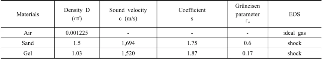
Table 2 shows the material properties for the sand and polymer gel, which are required to complete the shock EOS. In Table 2, “D” represents the density,
“C” the elastic wave propagation speed, and “S” a coefficient related to the moving velocity of impacted material; these were obtained from Hugoniot shock
equations (Awoukeng et al., 2014).
「∘ is the Gruneisen parameter used in the shock EOS. The Gruneisen parameter and elastic wave propagation speed have a minimal effect on the maximum pressure in the higher level of the shock equation, while density has the maximum impact.
The relationship between shock velocity (Us) and particle velocity(Up) is defined as:
Us = C + SUp (1)
In equation (1), Us is the shock velocity and Up is the particle velocity.
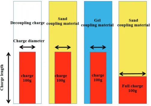
Numerical simulations were conducted for the charging conditions of the concrete blocks as shown in Fig. 6. The shape of concrete block model and pressure gauges, which were placed at center of the concrete block in X and Y directions to measure the pressure history are shown in Figs. 7∼8. An axisymmetric model was used for all the analyses to reduce the time required to complete the damage process of concrete block. The concrete block, covering sand (ground soil), and rock mass were
Decoupling charge Sand Polymer gel Full charge
Charge diameter (mm) 32 32 32 50
Charge length (mm) 105 105 105 105
Charge weight (g) 100 100 100 200
Crater volume (cc) 13,000 23,000 29,000 37,000
Crater index 0.6 0.9 1.05 1.3
Number of radial cracks 1 3 7 11
Relative strength 0.35 0.62 0.78 1.00
Table 1. Summary of crater test results for buried concrete blocks
Materials Density D (㎤)
Sound velocity c (m/s)
Coefficient s
Grüneisen parameter
「∘
EOS
Air 0.001225 - - - ideal gas
Sand 1.5 1,694 1.75 0.6 shock
Gel 1.03 1,520 1.87 0.17 shock
Table 2. Properties of coupling materials
Fig. 6. Schematics of charge conditions for numerical analysis.
(a) No coupling material (air) (b) Sand stemming & coupling
(c) Gel stemming & coupling (d) Full charge & sand stemming Fig. 7. Numerical models for crater tests of concrete blocks.
considered as Lagrangian parts with the rock properties given in Table 3. The parameters alpha and beta are compression-state exponential interpolation parameters, “A” is bulk modulus (kbar), “es” is sublimation energy, “eo” is energy of incipient, and
“esd” is the energy of complete vaporization. The material properties of the concrete having a compressive strength of 35 MPa was selected from the AUTODYN library. The coupling material and explosives inside the blast hole were modeled as
Eulerian parts, and the Euler–Lagrange coupling scheme (fluid-structure interaction technique) supported by AUTODYN was used for the simulations.
A JWL equation was used for the emulsion explosive (Table 4). An internal energy of 206800 J/kg was assumed for the air in the standard atmospheric condition. A flow-out condition was used for the boundary of the Eulerian parts. The numbers of elements in the Eulerian and Lagrangian parts were 10000 and 20000, respectively.
Rock Granite
Reference density 2.75 g/㎤
EOS Tilloston
Parameter γ 5
Parameter β 5
Parameter A 18,000,000 Kpa
Parameter es 18,000,000 Kpa
Parameter esd 0.018 j/kg
Parameter eo 0.016 j/kg
Table 3. Mechanical properties of rock (Lagrange) (Mel ‘Nikov et al., 1979)
Fig. 8. 3D profile showing the concrete blocks surrounded by soil (ground) and rock and the measurement locations (numbers within rectangles).
A (Gpa) B (GPa) R1 R2 ω
243 7.671 4.991 1.967 0.499
Table 4. JWL material properties for emulsion explosive
Fig. 9. Reason of a higher pressure and smaller damage area in full-charge case compared to stemming and coupling cases.
(a) No stemming and coupling (b) Sand stemming and coupling
(c) Gel stemming and coupling (d) Full charge with sand stemming Fig 10. 3D models showing damage area around the blasthole.
3.2 Analysis results
Although the broken elements still remain stick together through the simulation process due to the limitation of AUTODYN, the fragmented parts can be considered as the damage area. These damage areas may represent the craters.
The case with the polymer gel exhibited the secondly highest pressure peak and have shown a larger damage area around the blasthole compared to the other three cases. In the full-charge case in which the charge of 100 g was at the bottom of the blasthole, the peak pressure appeared to be higher, but the damage area was found to be smaller than those of the cases using the coupling and stemming.
Fig. 9 are the schematics showing how the shock waves travel in the cases of the full-charge condition and the other stemming and coupling conditions. The configurations (model shapes and gauge locations) were made to be the same in all of the cases to
obtain correct results. Figs. 10 and 11 show the damage areas around blasthole and the pressure peaks obtained from the four analysis models.
3.3 Discussions
To compare and analyze the effects of different coupling materials on the blast results, pressure histories were calculated in the vicinity of the blasthole. The maximum pressures were found to be 16, 30, 37, and 52 MPa, respectively, for the cases of no coupling, sand, polymer gel, and full charge. X and Y particle velocities appeared to be higher in the case of the full charge compared with the other cases.
But it was because the charge was closest to the gauge locations (Fig. 12).
During the explosion, the pressures of fluid materials such as water and polymer gel exhibit a pulsating motion after reaching the maximum pressure. In addition, their pressures are maintained
(a) No stemming and coupling (b) Sand stemming and coupling
(c) Gel stemming and coupling (d) Full charge with sand stemming Fig. 11. Pressure histories for different coupling materials.
(a) X and Y particle velocities of decoupling condition
(b) X and Y particle velocities of sand stemming & coupling material
(c) X and Y particle velocities of gel stemming and coupling material
(d) X and Y particle velocities of full charge with sand stemming Fig. 12. X and Y particle velocities for different stemming and coupling materials.
for a longer period compared to the cases of using other ordinary coupling materials. After reaching the maximum pressure, the gases that are generated as byproduct of the explosion form gas bubbles after the shock wave have passed by, and then the gas bubbles continue to display periodic pulsating motion.
4. Conclusions
In general, water is an excellent coupling and stemming material that provides good explosion results. However, water is a material which is difficult to seal and maintain its shape so that there are some difficulties in using it as a stemming and coupling material in a blasthole. In this study, it was demonstrated that a polymer gel can be substituted for water as an excellent stemming and coupling material that can transfer shock waves efficiently to surrounding rock mass and thus overcome the aforementioned shortcomings of water. To test the feasibility of the selected matters, both crater tests using concrete blocks and associated numerical analyses were conducted for different stemming and coupling conditions. The important conclusions are summarized as follows:
1) The results of the numerical analyses shows the same patterns as those of the crater tests. The damage area and pressure peaks around the blast hole were the largest in the case of the polymer gel, which were followed by the cases of sand and air. It was found that if the polymer gel is used as stemming and coupling materials, less amount of explosive will be required in comparison to the corresponding amounts of explosive when other coupling materials are used.
2) The pressure peak obtained from the use of the polymer gel was most similar to that from the full charge.
3) It is thought that the polymer gel can exhibit a
positive effect on explosion magnitude owing to the pulsating motion of fluid, provide a higher workability, and eliminate the requirement for sealing.
4) In the crater tests using buried concrete blocks, the polymer gel exhibited a superior performance compared to the other coupling materials.
5) Cost-effectiveness is an another advantage of the polymer gel. It is cheaper than sand.
6) In the numerical simulations, a higher pressure and smaller damage area appeared in the case of full charge, though the explosive quantity was the same for all of the cases. It is thought that this result happened because the charge was more concentrated at the bottom of the blasthole in the case of the full charge.
Acknowledgements
This work was supported by a grant from the Korea Agency for Infrastructure Technology advancement (KAIA) funded by the Ministry of Land, Infrastructure and Transport (Grant 18CTAP-C129771-02).
References
1) Ahmed, M., 2013, Hydrogel: Preparation, characterzation, and applications: A review, Vol. 6, Issue 2, pp. 1.5-121.
2) Antoun, T., E. Herbold and S. Johnson, 2012, Dynamic behavior of sand: Annual Report FY 11, Lawrence Livermore National Laboratory. Vol. 11, LLNL-TR- 539077
3) Awoukeng, A., L. Taddei, F. Tostain and S. Roth, 2014, Investigations of impact biomechanics for penetrating ballistic cases, Bio-med Mater Eng., vol. 24, no. 6, pp. 2331–9.
4) Bohloli, B., G. Gustafson, B. Ronge, 2001, A laboratory study on reducing the quantity of rock fines at failure:
application to rock blasting and crushing. Bull Eng Geol Env, Vol. 60, pp. 271–276.
5) Dai, C., G. Zhao, Q. You, M. Zhao, 2013, A Study on Enviornment- Friendly Polymer Gel for Water Shut-off Treatments in low- Temperature Reservoirs, Journal of applied Polymer Science. Sci 131, 40154-7.
6) Hamilton, L., 1969, Sound velocity and related properties
9) Mel’Nikov, V., L. N. Marchenko., I. F. Zharikov., and N. P. Seinov., 1979, A method of enhanced rock breaking by blasting, Soviet Mining Science, Vol. 15, No. 6, pp. 565-572.
rocks, International Journal of Rock Mechanics &
Mining Sciences, Vol. 45, pp. 111–121.
Khaqan Baluch
전남대학교 에너지자원공학과 박사과정
Tel: 062-530-0824
E-mail: [email protected]
김 정 규
전남대학교 에너지자원공학과 박사후연구원
Tel: 062-530-0823
E-mail: [email protected]
고 영 훈
한국건설기술연구원
인프라안전연구본부 수석연구원
Tel: 031-9100-640
E-mail: [email protected]
김 승 준
전남대학교 에너지자원공학과 박사후연구원
Tel: 062-530-0824
E-mail: [email protected]
정 승 원
전남대학교 에너지자원공학과 석사과정
Tel: 062-530-0824
E-mail: [email protected]
양 형 식
전남대학교 에너지자원공학과 교수
Tel: 062-530-1724 E-mail: [email protected]
김 용 기
두산건설 토목환경BG 설계팀
Tel: 010-9982-7548
E-mail: [email protected]
김 종 관
한국광물자원공사 기술기획팀
Tel:
E-mail: [email protected]