18관절 2족보행 로봇의 안정한 모션제어에 관한연구
A Study on Stable Motion Control of Biped Robot
with 18 Joints
박문열
1*
, Le Xuan Thu2
, 원종범3
, 박성준4
, 김용길5
Youl-Moon Park, Le Xuan Thu, Jong-Beom Won,Sung-Jun Park, Yong-Gil Kim
<Abstract>
This paper describes the obstacle avoidance architecture to walk safely around in factory and home environment, and presents methods for path planning and obstacle avoidance for the humanoid robot. Solving the problem of obstacle avoidance for a humanoid robot in an unstructured environment is a big challenge, because the robot can easily lose its stability or fall down if it hits or steps on an obstacle. We briefly overview the general software architecture composed of perception, short and long term memory, behavior control, and motion control, and emphasize on our methods for obstacle detection by plane extraction, occupancy grid mapping, and path planning. A main technological target is to autonomously explore and wander around in home environments as well as to communicate with humans.
Keywords : Humanoid Robot, Obstacle Avoidance, Motion Control
1*정회원, 교신저자, 경남대학교 첨단공학과, E-mail:[email protected]
2정회원, 파나소닉베트남㈜
3정회원, ㈜스맥 대표이사
4정회원, 전남대학교 전기공학과 교수, 工博
5정회원, 경남대학교 기계공학부 교수, 工博
1. INTRODUCTION
This paper describes obstacle avoidance architecture allowing Walking Humanoid Robots to walk safely around in factory and home environment1).
For a wheeled robot, many solutions on this subject have been presented in the literature using ultrasonic sensors or laser range finders and they mainly detect walls and relatively large obstacles around the robot. But solving the problem of obstacle avoidance for a humanoid robot in an unstructured environment is a big challenge, because the robot can easily lose its stability or fall down if it hits or steps on an obstacle 2)-3) .
This strategy focuses on floor estimation, because in our view information about the floor is most important for a humanoid robot while walking. For this purpose, it was developed a stereo-vision system and detect the floor plane using a randomized version of the Hough transform. The aim of this proposition is to establish a new industry involving autonomous robots and artificial intelligence 4)-6) .
A main technological target of KMHROBO is to autonomously explore and wander around in home environments as well as to communicate with humans.
2. SYSTEM ANALYSIS
2.1 Overview
The KMHROBO consists of 2 microphones for speech recognition and sound localization utilizing as well as speech synthesis play a big
role in the communication capabilities of Robot. Audio and visual recognition results are memorized in a system that reflects the current environment. The stereo-vision system consists of 2 cameras as the robot’s eyes and a module for stereo processing in the robot’s head. Using its stereo camera KMHROBO can compute distance to objects, extract a floor plane and generate a path for walking around obstacles.
KMHROBO is able to communicate with network computers by utilizing its wireless LAN.
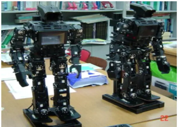
The KMHROBO consist of 18 joints of the intelligent servo actuators. In real time, it enables KMHROBO to walk adaptively on inclined and irregular terrain and allows the robot to re-stabilize immediately even when external forces affect its balance. Furthermore, a sub-system for real time step pattern generation realizes various walking patterns ranging from active and stable biped walking to moving flexibility.
Fig 1. The image of the KMHROBO.
2.2 Structures
Base on the height of KMHROBO, the Robot’s structure and the main applications for the stereo system, the distant between 2 color CCD cameras is 4cm. This distant allows for reliable floor estimation up to a range of 3m and reliable distance estimation of other objects in the range of 20cm to 4m.
The system consists of an 8-bit micro processor with two 16Mbyte SDRAM units and a flash ROM. The stereo-vision module computes disparity between 2 CCD cameras by using block matching receives a pair of images from them. The main board of the CPU receives the resulting disparity image as a digital video signal. The stereo control parameters can be set between the main CPU and the 8bit CPU on board through a special serial communication link(see Fig. 2).
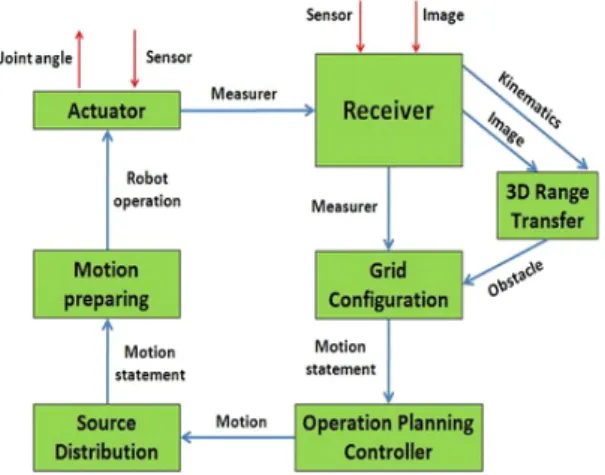
The system’s software briefly describes each module below (see Fig. 3).
Fig. 2. System’s hardware.
Fig. 3. The function blocks in system.
a) The Receiver module:
The important point of this module is that to deliver disparity images with the corresponding kinematic transformations to the 3D Range Transfer module. This module receives image data from the stereo-vision system and joint angle sensor data from each actuator.
b) 3D Range Transfer module
This module aims at to convert all the 3D measurements to the floor coordinate system.
The disparity image obtained from stereo- vision is first converted into 3D range data using parameters from stereo calibration. Then a transformed data is applied for finding planes in the 3D data.
c) The Grid Configuration module
It integrates information into a 2D grid
configuration of size 3.5x3.5m around the
robot. Image source: receiving either from the
3D Range Transfer or odometer info- rmation from the Receiver module.
d) The Operation Planning Controller
module
Control mechanism where the behavior of the robot is determined autonomously according to internal states and external observations. A part of Operation Planning Controller is a planning pioneer that, given a goal point, computes a collision-free path leading to the destination. The planning pioneer system then generates walk and head motion commands which are sent to the Source Distribution which in turn send them to the Motion preparing and the Actuator.
The vision system (mentioned above) receives image from the two CCD cameras.
These parameters are useful for computing 3D range data. The disparity is calculated for each pixel in the left image by searching for the corresponding pixel in the right image.
An additional reliability image is calculated following criteria to reject results on above conditions. After block matching has been carried out, the matching score is calculated by interpolating scores near the highest peak.
The sharpness of this peak corresponds to the available texture around this pixel and thus can be used as a reliability value for the disparity calculation. If there are other peaks with similar matching scores then the disparity computation is ambiguous and the reliability is set to a low value. (The matching score is compared with neighboring scores).
3. OPERATION
The method for estimating the parameters of a surface from a set of measured samples is called Hough transformation.
The randomized Hough transformation is the method to be applied if the number of sample points and parameters to be estimated is large, because apply the Hough trans- fomation method is expensive in this case.
Firstly, the disparity is converted into 3D range data using the parameters from camera calibration and then a Hough transformation is applied to all data points. Apply the randomized Hough transformation selects sets of data points from which the surface parameters can be directly computed and records the result in a table. If many data sets yield the same parameters, a high score for these parameters is obtained.
The details of this method are showed in the flow chart in the Fig. 4 below.
Although applying floor detection methods, obstacles and regions the robot can walk on can be found. However, in general it is difficult to decide from a single observation with a limited field of view, the action the robot should carry out next. We follow this notion and introduce a terrain map where all observations and motions are integrated.
The terrain map is a 2-dimensional occupancy
grid centered on the current position of the
robot (egocentric coordinate system). We
maintain the (global) robot orientation and a
small relative (x y) location of the robot within
the cell at the center of the grid. Initially, all
Fig. 4. Flow chart of plane extraction
cells are set to a probability of 1.0 and time 0.
Each grid cell contains the probability that an obstacle covers the cell and the time the cell was last updated.
T h e r o b o t m o t i o n i s d e f i n e d a s a coordinate transformation from one foot to the other whenever the robot performs a step. From this transformation a displacement and a change in orientation can be derived and applied to the position and orientation of the robot in the grid.
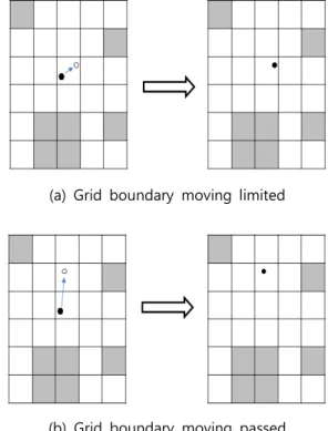
(a) If the robot stays within the cell at the center of the grid, no further actions have to be performed (see Fig. 5 (a)).
(b) If the robot crosses the cell’s boundary, w e s h i f t t h e g r i d b y t h e n u m b e r
(a) Grid boundary moving limited
(b) Grid boundary moving passed Fig. 5. Occupancy Grids update method
of cells the robot passed in each direction (Fig. 5 (b)).
In implementation shifting the grid is actually performed by changing an offset into the grid data array so that no data has to be moved physically. After shifting the coordinate system of the occupancy grid, new cells at the border are initialized.
Define: the cell size Sc, the robot position (Rx, Ry) inside the grid, and the moving displacement (Mx, My), we obtain:
÷÷ ø ö çç è
æ ÷
ø ç ö
è
æ +
÷ ø ç ö
è
æ +
= Sc
My Ry Sc
Mx Ay Rx
Ax , ) ,
( (1)
Fig. 6. Update method of Occupancy Grids (Rotate operation)
The new robot position inside the grid becomes as follows:
) , ( ) ,
(
Mx
-Sc
×Ax My
-Sc
×Ay
®Rx Ry (2)
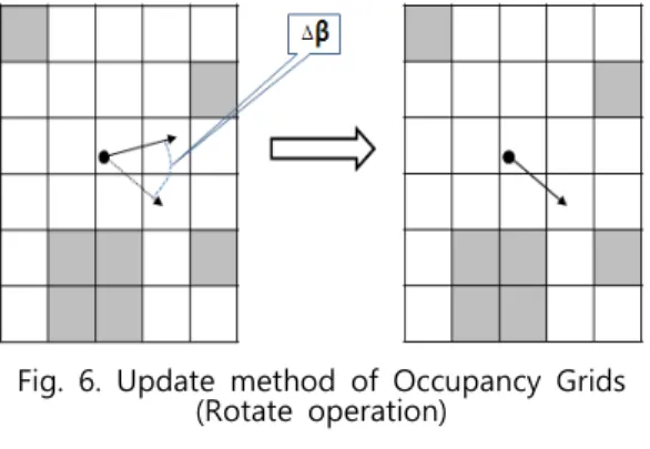
The change in orientation is simply added to the global orientation of the robot (Fig. 6).
In an additional, searching for shortcuts along the found path, a smooth walking trajectory is realized.
The robot can find a path to a destination point by using the occupancy grid reflects the terrain around. The definition of each cell of the occupancy grid is a node connecting to neighboring cells and defines the path planning problem as a search problem on this graph.
· The initial posture of the KMHROBO is β (degree). The angular rotation is ∆β.
· The posture after rotating is β +∆β.
The potential ′ at node to an obstacle ′ is calculated as a repulsive potential from the obstacle probability ( ′ :
)) ' , ( , max(
) ' ) (
' ,
(
0
k k E E
E k k O
k U
s
=
(3)
where
E(k,k') : Euclidean distance between k and k'
E0 : A safety margin to ensure the robot does not steps on or hit any obstacle.
U(k) : The potential of a node k.
( ) max ( , ' )
) ( '
k k U k
U
k K k Î
= (4)
(Chose the U(k) as the maximum of U(k,k') over all nodes k' close to node k)
Note that the E(k) reflects the optimal estimated cost for passing through node k.
By expanding nodes k with minimal E(k) value, the optimal solution can be found.
The evaluation function is:
) ( )
( )
( k D n C n
E = +
b× (5)
å +
=
k
k
sta s
k k L k U k
D ( ) ( ) ( , )
(6) )
, ( ) , ˆ ( )
( k L k k U k k
C = des = des (7)
where
E(k) : Resembles the path cost from start node ksta to current node k
C(k) : Estimated path cost from the current node k to the destination node kdes
: Weighting factor.
L(ksta,k) : Path distance between ksta and k
L(kdes,k) : Path distance between k and
kdes.
4. RESULTS AND CONCLUSION.
The autonomous mobility for the biped robot KMHROBO in the home environment is realized base on the development of a small stereo vision system, the recognition of floor and obstacles using plane extraction.
The terrain is represented in a robot centric coordinate system without making any structural assumptions about the surrounding world. And the representation of a terrain map based on these observations, robot motion, and the generation of a walking path on the terrain map. We therefore believe, our approach is well suited for many different a home environment where no a priori information about the environment is given.
The limitation of our system is that the terrain has to contain enough texture in order to obtain reliable stereo data.
REFERCES
1) D. Pagac, E. Nebot and H. Durrant - Whyte, “An evidential approach to map-building for autonomous vehicles,”
IEEE Transactions on Robotics and Automation, 14(4), pp.623-629, (1998) 2) Ole Wijk, ”Triangulation Based Fusion of
Sonar Data with Application in Mobile Robot Mapping and Localization,” PhD thesis, Royal Institute of Technology, Stockholm, Sweden, (2001)
3) H. S. Choi, C. H. Jeon, and J. H. Oh
“Automatic Motion Generator and Simulator for Biped Walking Robots”
KSPE pp.106-111, (2004)
4) J..H.Shin, W.H.Kim, and M.N.Lee, “Robust Adaptive Fuzzy Tracking Control Using FBFN for AMobile Robot with Actuator Dynamics” Journal of institute of Control, Robotics and Systems(in Korean), vol.16, no.4, pp.319-328, (2010)
5) S. Kim, K. Seo, and Y. Cho, “A Trajectory Tracking Control of Wheeled Mobile Robot Using a Model Reference adaptive Fuzzy Controller” Journal of institute of Control, Robotics and Systems(in Korean), vol.15, no.7, pp.711-719, (2009)
(접수:2014.03.03, 수정:2014.04.16, 개제확정:2014.04.28)