한국정보통신학회논문지(J. Korea Inst. Inf. Commun. Eng.) Vol. 20, No. 3 : 607~614 Mar. 2016
발전소 케이블 포설에서 Raceway의 유연한 케이블 Fill 체크 기반 자동화된 케이블 라우팅 설계
박기홍 · 이양선*
Automated Cable Route Design based Flexible Cable Fill Check of Raceway in Cable Spreading of Generating Station
Ki-Hong Park · Yang Sun Lee*
Divison of Convergence Computer & Media, Mokwon University, Daejeon, 35349, Korea
요 약
발전소 설비에서 케이블 포설을 위한 설계는 발전소 설비에 사용되어지는 케이블 유형의 다양한 형태로 인해 매 우 많은 시간이 요구되고 매우 중요한 과제이다. 케이블 포설 설계 시 레이스웨이(Raceway)는 출발지(Source) 장비 로부터 목적지(Destination) 장비까지의 케이블 트레이(Tray) 및 콘디트(Conduit)의 포설 구간을 의미한다. 기존의 케이블 포설 설계 과정은 모두 수기에 의해 작성되어 인적/시간적 투자손실이 크고, 케이블의 누락 및 케이블 오버필 (Over Fill)과 같은 비효율적인 손실이 빈번히 발생한다. 따라서 본 논문에서는 효과적인 발전소 케이블 포설 설계를 위한 레이스웨이의 유연한 케이블 오버 필(Fill) 체크 기반의 자동화된 케이블 라우팅 경로 계산 알고리즘을 구현하 였고, 제안한 자동화 케이블 라우팅 설계기법은 케이블 위치의 변화에도 유연한 레이스웨이 계산이 가능하다. 구현 결과, 케이블 라우팅 설계 프로그램은 발전소 케이블 포설 설계 사양을 준수하면서 케이블 라우팅 경로를 효과적으 로 설정하고, 케이블 포설 설계 시간을 기존 대비 크게 단축하는 성능을 얻을 수 있었다.
ABSTRACT
In generating station, cable spreading design is a very important task, which is very much time consuming, due to the type of cable used in generating station is very diverse. The raceway means the cable line section from source equipment to destination, and consists of cable tray and conduit. The process of existing cable spreading design was written in by hand. Thereby, there are grossly inefficient gain such as cable omission and unfixed fill value by a personal and time investment. In this paper, we proposed and implemented the automated cable route design based flexible cable fill check in generating station, and proposed the automated cable route design can be calculated the cable fill with flexible changing of raceway. Some experimental result shows that implemented cable route design is well performed and conducted as the design specifications, and it will be able to reduce the cable spreading design time.
키워드 : 케이블 포설, 케이블 필, 레이스웨이 구성, 콘디트, 케이블 트레이
Key word : Cable spreading, Cable fill, Raceway configuration, Conduit, Cable tray
Received 08 December 2015, Revised 29 December 2015, Accepted 12 January 2016
* Corresponding Author Yang Sun Lee(E-mail:[email protected], Tel:+82-42-829-7638) Divison of Convergence Computer & Media, Mokwon University, Daejeon, 35349, Korea
Open Access http://dx.doi.org/10.6109/jkiice.2016.20.3.607 print ISSN: 2234-4772 online ISSN: 2288-4165 Communication Engineering
Ⅰ. INTRODUCTION
Recently, a number of generating station construction projects around the world has been proceeding for securing energy. Effective cable spreading design in generating station construction is a very important task without the redesign and design errors. The type of cable has at least 40,000 or more due to the characteristics of the electrical installation engineering, and raceway types such as conduit and tray also vary [1-3]. However, the design of the electrical installations for generating station construction is still carried out by hand, so it has personal and temporal investments inefficiency. In particular, the conventional electrical installation design is time consuming at least six months or more depend on design scale, and it may also entail unnecessary error such as cable omission, cable shortage and more than the reference value with unfixed cable fill. Therefore, the automation of cable spreading design, including cable systems, raceway types, cable fill and cable drum schedules, is a very important process for effective cable spreading design without errors that can occur frequently. This process should be implemented with a function which allows the designer to perform raceway cable fill calculation effectively. In addition, the designer must have access to the raceway and cable information, and this should be easy to modify to minimize design errors.
In order to effectively automate the cable installation, we proposed and implemented the cable installation program which can be done cable spreading plan for generating station construction. Proposed the cable installation automation, which is coded the raceway and cable, can calculate the cable fill, raceway route and optimal scheduling of the cable drum.
The paper was organized as follows. Section 2 describes the concept of raceway route and raceway code design, Section 2 was devoted to the cable code definition and the design. Section 4 discusses the cable fill calculation, and Section 5 presents the result of the design of cable drum schedule. The final section is
devoted to conclusion and pointing to some further issues.
Ⅱ. Raceway Configuration
2.1. Raceway Definitions
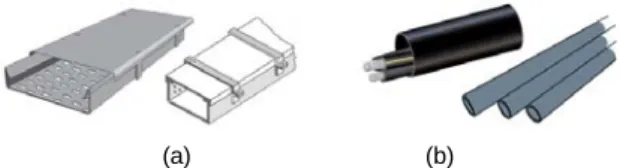
Raceway systems consist primarily of cable tray and conduit [4]. Cable trays are used as an alternative to open, and are commonly used for cable management in commercial and industrial construction. As shown in figure 1, a cable tray system is also used to support insulated electric cables used for power distribution or communication, and an electrical conduit is a tube used to protect and route electrical wiring in the electrical wiring of buildings.
(a) (b)
Fig. 1 The types of raceway system (a) cable tray (b) conduit
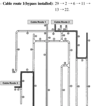
Raceway should be adequately sized as determined by the maximum recommended percentage fill of the raceway area, which is explained in more detail in Section 5. The raceway means the cable line section from source equipment to destination. Figure 2 shows the concept of raceway which is installed cables depending on the type of raceway, and the outline of cable routes are given below.
- Cable route 1: 29 → 35 → 5 → 13 → 22.
- Cable route 2: 31 → 2 → 3 → 36 → 7 → 19 → 15.
- Cable route 3: 30 → 27 → 20 → 17 → 21.
Cable route 1 and route 2, for example, consists of four and six cable line section, respectively. If the cable line section 5 and 35 is more than the maximum recommended fill in cable route 1, it must be installed to
bypass the cable as shown below.
- Cable route 1(bypass installed): 29 → 2 → 6 → 11 → 13 → 22.
Fig. 2 The concept of raceway for cable installation in generation system
2.2. Raceway Code Design
In this paper, we designed the raceway code which consists of unit, area, service level, raceway type and serial as figure 3. The unit code means the plant type such as hydroelectric, thermoelectric, gas turbine and nuclear power plant. The area code, small classification of the unit, presents the locations including control building, gas turbine generator (GTG), steam turbine, heat recovery steam generator (HRSG), cooling tower, and so on. The service level code of figure 3 is cable circuit classifications, and is designed to supply power to utilization devices of a plant auxiliary system. The serial code was added as extra purposes of design management. Finally, raceway code is designed with the following configuration, and it can be redefined differently depending on the type of power plant.
- HOT DIP GALANIZED CONDUIT.
- RIGID POLYVINYL CHLORIDE THIN PIPE.
- UNPLASTICIZED POLYVINYL CHLORIDE CONDUIT.
- GALVANIZED STEEL TRAY.
Fig. 3 Raceway code derivations
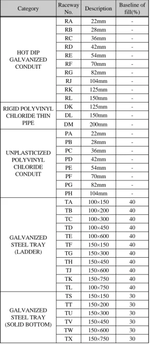
Table 1 shows the design information of unit and area code. Code information presented in table 2 through 4 is service level code, serial code and raceway code. If the raceway code ‘2GK01TD’ defined based on figure 3, it means a galvanized steel tray which is the size of 100×450, and this tray is installed in the gas turbine room of GTG building.
Table. 1 Unit and area code
Unit Description Area Description
0 COMMON C CONTROL BUILDING
1 GTG#1 G GAS TURBINE
2 GTG#2 H HRSG. AREA
3 BOP S STEAM TURBINE
- - T COOLING TOWER
Table. 2 Service level code
Service Level Description
A 345kV CABLES
B 154kV CABLES
C 6.9kV CABLES
H 480V LOAD CENTER CABLES
K 480V POWER FROM MOTOR CONTROL CENTER
L~N AC AND DC CONTROL (220V, 110V AC/125V, 24V DC)
X~Z INSTRUMENTATION AND ANALOG COMPUTER INPUT
Table. 3 Serial No. code
Serial No. Description
01 FOR TEST
02 SERIAL NO.
Table. 4 Raceway code Category Raceway
No. Description Baseline of fill(%)
HOT DIP GALVANIZED
CONDUIT
RA 22mm -
RB 28mm -
RC 36mm -
RD 42mm -
RE 54mm -
RF 70mm -
RG 82mm -
RJ 104mm -
RK 125mm -
RL 150mm -
RIGID POLYVINYL CHLORIDE THIN
PIPE
DK 125mm -
DL 150mm -
DM 200mm -
UNPLASTICIZED POLYVINYL
CHLORIDE CONDUIT
PA 22mm -
PB 28mm -
PC 36mm -
PD 42mm -
PE 54mm -
PF 70mm -
PG 82mm -
PH 104mm -
GALVANIZED STEEL TRAY
(LADDER)
TA 100×150 40
TB 100×200 40
TC 100×300 40
TD 100×450 40
TE 100×600 40
TF 150×150 40
TG 150×300 40
TH 150×450 40
TJ 150×600 40
TK 150×750 40
TL 100×750 40
GALVANIZED STEEL TRAY (SOLID BOTTOM)
TS 150×150 30
TT 150×200 30
TU 150×300 30
TV 150×450 30
TW 150×600 30
TX 150×750 30
Ⅲ. Cable Code System
This section establishes the cable code information that shall be utilized in specifying cables. Cables shall
have a qualified life for all service conditions that are postulated for the areas where they are to be used and shall be qualified in accordance with IEEE standard 323-1983 and ANSI/IEEE standard 383-1974 [5].
3.1. Cable Circuit Classifications
Cable selection should be considered in the selection of cable for installation in power generating stations. In [5], the recommendation for cable circuit classifications has been presented.
3.2. Cable Code Design
A balance of cable characteristics method to the environmental conditions of the power plant is very important due to section 3.1. Depending on the plant type, installation site and purposes, cable selection can vary, but most cable characteristics can be of a cable type, the number of conductors and the size of conductors as in figure 4.
Fig. 4 Cable code derivations
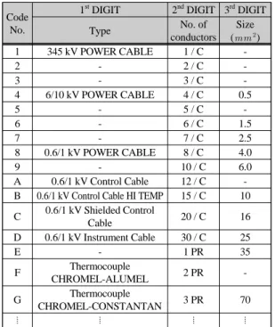
Table 5 shows the designed cable code, and was designed based on figure 4. Assuming that the cable code is ‘848’, this means the power cable rated 345kV to less with four conductors and an conductor size 4
, and the cable code can be configured in various ways as follows. Table 4 shows the example of designed cable code.
- Cable code ‘848’: power cable, 0.6/1kV 4C×4. - Cable code ‘1BL’: power cable, 345kV 15C×240. - Cable code ‘A39’: control cable, 0.6/1kV 3C×6. - Cable code ‘D4B’: instrument cable, 0.6/1kV
4C×10.
Table. 5 The example of cable code design
Code No.
1st DIGIT 2nd DIGIT 3rd DIGIT
Type No. of
conductors Size ()
1 345 kV POWER CABLE 1 / C -
2 - 2 / C -
3 - 3 / C -
4 6/10 kV POWER CABLE 4 / C 0.5
5 - 5 / C -
6 - 6 / C 1.5
7 - 7 / C 2.5
8 0.6/1 kV POWER CABLE 8 / C 4.0
9 - 10 / C 6.0
A 0.6/1 kV Control Cable 12 / C - B 0.6/1 kV Control Cable HI TEMP 15 / C 10 C 0.6/1 kV Shielded Control
Cable 20 / C 16
D 0.6/1 kV Instrument Cable 30 / C 25
E - 1 PR 35
F Thermocouple
CHROMEL-ALUMEL 2 PR -
G Thermocouple
CHROMEL-CONSTANTAN 3 PR 70
⁞ ⁞ ⁞ ⁞
Ⅳ. Raceway Calbe Fill Calculation
4.1. Raceway Cable Fill Requirements
This section establishes requirements for the construction methods and materials for the handling and installation of cable systems. As of 1984 IEEE standard 690-1984 [5], IEEE standard for the design and installation of cable systems for class 1E circuits in nuclear power generating stations, is completed and is being validated by commercial and industrial construction. In the reference [6], the raceway cable fills recommendations as follows.
- The number of cables in any tray or conduit shall be limited by cable ampacity requirements.
- A cable tray filled to the predetermined quantity (design limit) shall not be used for further cable routes, unless an inspection or an analysis has been made that indicates additional cables can be installed.
- An analysis shall be made to determine the range of
weight of cable loading and this figure shall be used in the seismic analysis of the cable-tray support system.
These loadings shall not be exceeded by placing more cables in the tray than allowed by the seismic design.
- Conduit fill shall be in accordance with ANSI/
NEPA-70-1984, unless an analysis has been made that indicates that additional cables can be installed.
4.2 Automation of Cable Fill Calculation
This section describes the process of raceway cable fill calculations in case of cable tray and conduit. Figure 5 shows the cross-section of cable and the concept of cable tray and conduit, and outside diameter (OD) is used to calculate fill in the cross-section of cable. The sum of area (SoA) means the cross-sectional area (CSA) of cable tray or conduit, and an area of cable (AoC) is a cross-sectional of a cable as in formula (1).
Fig. 5 The cross-section of cable, and the structure of cable tray and conduit
×
×
(1)
Raceway cable fill, for example, summation of the cable cross-sectional area, in random filled cable trays should be limited in design to a predetermined percentage of cable tray usable cross-sectional area. A percentage fill limit is needed for random filled trays because cables are not laid in neat rows and secured in place. This results in cable crossing and void areas which take up much of the tray cross-sectional area.
Generally, a 30% to 40% fill for power and control cable and 40% to 50% for instrumentation cables will result in a tray loading so that no cable will be installed above the top of the side rails of the cable tray except as necessary at intersections and where cables enter or exit
the cable tray systems [6-8]. If two cables ‘838’ and
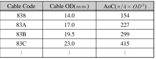
‘83C’ are installed in raceway ‘2GK09TD’ and the cable OD value is given as shown in table 6, raceway cable fill is calculated as follows.
- An area of raceway code ‘TD’ is 45,000 (100×450
, as shown in table 4) and the baseline of fill is 40%, therefore SoA is 18,000.
- Since OD of cable code ‘838’ is 14, AoC of cable code ‘838’ is 154. Likewise, AoC of cable code
‘83C’ is 425 with cable OD size of 23. - The CSA of two cables in raceway ‘2GK09TD’ is
accounted for 4.22% of SoA capacity.
Table. 6 An area of cable according to cable OD value Cable Code Cable OD() AoC( ×)
838 14.0 154
83A 17.0 227
83B 19.5 299
83C 23.0 415
⁞ ⁞ ⁞
In case of conduit, because of conduits and tubing from different manufacturers have different internal diameters for the same trade size, Table 7 shows the diameter and the actual area of different raceway for 31, 40, and 53 percent fill [7].
Table. 7 Percentage of cross section of conduit and tubing for conductors
Number of Conductors All Conductor Types
1 53 %
2 31 %
Over 2 40 %
Table 7 is based on common conditions of proper cabling and alignment of conductors. It should be recognized that, for certain conditions, a larger size or a lesser conduit fill should be considered. Table 8 shows the percentage of conduit fill depending on cable OD and the number of its conductors.
Table. 8 The baseline of fill for conduit according to the number of cables
Cable OD ()
AoC ( ×)
Fill of a Cable (53%)
Fill of Two Cables (31%)
Fill of Three Cables (40%)
22 380 201 118 152
36 1,018 539 316 407
104 8,495 4,502 2,633 3,398
⁞ ⁞ ⁞ ⁞ ⁞
Let’s assume that cable code ‘83A’ is spread in the raceway as shown in Figure 6 and 7.
Fig. 6 Example of installation path (R1, R2 and R3) of cable code ‘83A’
Fig. 7 Cable route information of cable code ‘83A’
including fill of each raceway
In Figure 6 and 7, the cable code ‘83A’ has been laid to sequentially 2GK22RD (R1), 2GK04TD (R2) and 2GK14RD (R3). This code is constituted by 7 bytes, and the last two bytes are raceway code as shown in Figure 3. The raceway code are also described in Table 4, ‘RD’
and ‘TD’ code has the following information.
- RD: HOT DIP GALVANIZED CONDUIT having a diameter ‘42’.
- TD: GALVANIZED TRAY having a height ‘100’
and a width ‘450’.
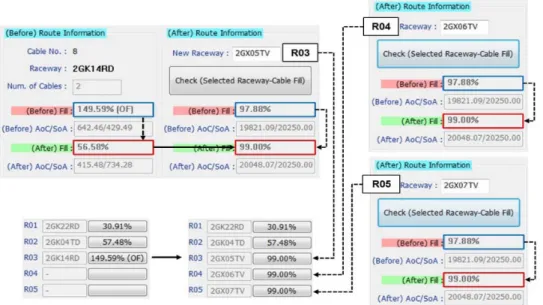
In Figure 8, the raceway ‘2GK14RD’ has a 149.6%, and it is a case of exceeding the baseline percent depending on the number of cable. Therefore, the cable
‘83A’ must be spread by bypassing the other raceway, and Figure 9 shows the cable passing including cable
‘83C’ and ‘83A’ through the raceway ‘2GK14RD’. By the cable ‘83A’ is laid to bypass from raceway
‘2GK14RD’ to ‘2GX05TV’, the cable fill of raceway
‘2GK14RD’ has become from 149.6% to 56.6% as shown in Figure 10. The cable fill of raceway
‘2GK14RD’, cable spreading before and after bypassing, is as follows.
- Before bypassing (two cable): (415+227)/
429 ×100(%) = 149.6%.
- After bypassing (a cable): 415/734×100(%)
= 56.6%.
The cable OD values of cable code ‘83C’ and
‘83A’are 23 and 17 as shown in Table 6, and each cable have AoC values of 415 and 227, respectively.
Also, 429 and 734, percent of cable fill, means the
baseline of fill for conduit according to the number of cables as shown in Table 7 and 8.
Fig. 8 Cable passing through the raceway ‘2GK14RD’
Fig. 10 Final installation path (R1, R2, R3, R4 and R5) of cable code ‘83A’
Fig. 9 Cable spreading process by bypassing cable ‘83A’ to other raceway
As shown in Figure 9, cable fill of raceway
‘2GK14RD’ has been changed from 149.6% to 56.6%, due to cable ‘83A’ is bypassed from raceway
‘2GK14RD’ to ‘2GX05TV’. Figure 10 shows the cable routes of cable ‘83A’ before and after bypassing to other raceway.
Ⅴ. CONCLUSION
Effective cable installation design is required for electrical equipment in generating station. This task is complex and too much time may be invested in designing them. The existing cable spreading design was proceeded in by hand, thus there are some inefficient gain by a personal and time investment.
Therefore, the method of automated cable spreading design is necessary for reducing cable omission and unfixed cable fill value. In this paper, we proposed and implemented the automated cable route design with flexible cable fill check. Cable fill should be calculated in a different way depending on the type of raceway, which means the cable line section from source equipment to destination. Experimental result shows that implemented cable route design is well performed and conducted as the design specifications, and it will be able to reduce the cable spreading design time.
REFERENCES
[1] IEEE Std. 1185-1994, IEEE Guide for Installation Methods for Generating Station Cables, IEEE Power & Energy Society, August 2002.
[2] National Fire Protection Association and Delmar, NEC 2011 Handbook, 12th edition, NFPA Publication, December 2010.
[3] Joseph V. Sheehan, Mark W. Earley, Jeffrey S. Sargent, John M. Caloggero and Timothy M. Croushore, National Electrical Code 2002 Handbook, 9th edition, NFPA Publication, December 2001.
[4] Insulated Conductors Committee. [Internet]. Available:
http://www.pesicc.org/iccWebSite/.
[5] IEEE Std. 690-1984, IEEE Standard for the Design and Installation of Cable Systems for Class 1E Circuits in Nuclear Power Generating Stations, Power Generation Committee of the IEEE and Power Engineering Society, 2002.
[6] IEEE Std. 422-2012, IEEE Guide for the Design of Cable Raceway Systems for Electric Generating Facilities, IEEE, 2013.
[7] IEEE Std. 690-2004, IEEE Standard for the Design and Installation of Cable Systems for Class 1E Circuits in Nuclear Power Generating Stations, Power Generation Committee of the IEEE and Power Engineering Society, 2005.
[8] Committee Report, “Recommended practice on specific aspects of cable installation in power-generating stations,”
IEEE Transactions on Power Delivery, Volume. 4, Issue 3, pp. 1504-1506, August 2002.
박기홍(Ki-Hong Park)
2010년 목원대학교 대학원 IT공학과 공학박사 2010년 ~ 2012년 ㈜인코넥스 책임연구원
2012년 3월 ~ 현재 목원대학교 융합컴퓨터미디어학부 조교수
※관심분야 : 영상처리, 컴퓨터비전, 패턴인식, 자동화시스템, 방재응용기술 등
이양선(Yang Sun Lee)
2007년 목원대학교 대학원 IT공학과 공학박사
2012년 Graduated School of Engineering, Fukuoka Institute of Technology(FIT), Japan 공학박사 2007년 ~ 2009년 (주)휴메이트 기술연구소 기획팀장/책임연구원
2009년 ~ 2011년 조선대학교 정보통신공학과 연구교수 2012년 ~ 현 재 목원대학교 융합컴퓨터미디어학부 조교수
※관심분야 : IT융합, 차량-IT, IoT, UWB, 가시광 무선통신, 전파성능분석 , 디지털 무선통신