Vol.20, No.3, (2018), pp.21~27 https://doi.org/10.9714/psac.2018.19.3.021
```
1. INTRODUCTION
In a typical reciprocating expander, there is a piston and a mechanical connection inside the cylinder. The motion of the piston is elaborately controlled by the mechanical connection to produce work effectively. As a result, the piston reciprocates in the cylinder while expanding the internal gas and extracting work. This has the advantage that it is easy to predict the performance by its simple operation. It contains, however, many mechanical moving parts inside the cylinder that cause irreversible loss due to friction and low reliability. This kind of reciprocating expander has a disadvantage in that it is difficult to manufacture and also maintain [1]. In order to overcome such disadvantages, a free-piston reciprocating expander in which a mechanical connection is removed has been developed. In a free-piston reciprocating expander, the movement of the piston is controlled by the pressure difference on both sides of the piston, unlike a typical reciprocating expander in which the mechanical connection controls the movement of the piston.
In 2004, MIT & AMTI developed a free-piston reciprocating expander for a small-scale Collins type 10 K cryocooler for space applications, one of the representative studies on free-piston reciprocating expander. The schematic of the expander is shown in Fig 1. (a). The four solenoid valves are operated at regular time intervals to
generate mass flow at each valve, then, the pressure difference on both sides of piston is adjusted [2]. J. Cha developed a free-piston reciprocating expander, replacing four reservoirs and solenoid valves with a reservoir and a single orifice valve that can adjust the opening, in 2016.
The schematic of the expander is shown in Fig 1. (b).
Similarly, a mass flow is generated through the orifice valve, then, the pressure difference on both sides of the piston is controlled [3].
Fig. 1. Schematic diagram of (a) floating piston expander and (b) phase controller expander [3].
Numerical and experimental studies of cryogenic reciprocating expander without inner piston
Sehyeon Park
*,a, Junhyuk Bae
a, Kyoungjoong Kim
a, and Sangkwon Jeong
aa
Korea Advanced Institute of Science and Technology (KAIST), Daejeon, Korea
(Received 13 February 2018; revised or reviewed 5 September 2018; accepted 6 September 2018)
Abstract
It is difficult to fabricate and maintain moving parts of expander at cryogenic temperature. This paper describes numerical analysis and experimental investigation on a cryogenic reciprocating expander without moving piston. An intake valve which takes high-pressure gas, and an exhaust valve which discharges low-pressure gas, are connected to a tube. The inside pressure of the tube is pulsated for work production. This geometric configuration is similar to that of pulse tube refrigerator but without regenerator.
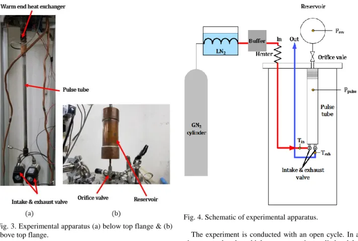
An orifice valve and a reservoir are installed to control the phase of the mass flow and the pressure. At the warm end, a heat exchanger rejects the heat which is converted from the produced work of the expanded gas. For the numerical analysis, mass conservation, energy conservation, and local mass function for valves are used as the governing equations. Before performing cryogenic experiments, we carried out the expander test at room temperature and compared the performance results with the numerical results. For cryogenic experiments, the gas is pre-cooled by liquid nitrogen, and then it enters the pulse tube expander.
The experiments are controlled by the opening of the orifice valve. Numerical analysis also found the expander conditions that optimize the expander performance by changing the intake pressure and valve timing as well as the opening of the orifice valve.
This paper discusses the experimental data and the numerical analysis results to understand the fundamental behavior of such a newly developed non-mechanical expander and elucidate its potential feature for cryogenic application.
Keywords: pulse tube expander, phase controller, numerical model, warm end heat exchanger, cryogenic
* Corresponding author: [email protected]
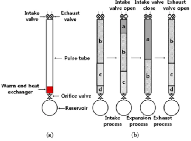
Fig. 2. (a) The schematic of the reciprocating expander without inner piston and (b) operating process.
The combination of such an orifice valve and reservoir is called a phase controller. The free-piston reciprocating expander reduces the friction loss by eliminating the mechanical connection with the piston. However, since the piston, which is a mechanical moving part, still exists inside the cylinder, friction loss and the manufacturing difficulty remains. Therefore, we develop a reciprocating expander in which the piston is completely removed. The role of a piston in a typical expander is replaced by a compressible gas column [4, 5].
The schematic diagram of the expander proposed in this study is shown in Fig 2. (a). An intake valve which takes high-pressure gas, and an exhaust valve which discharges low-pressure gas, are installed at one side. The cylinder in typical expander is replaced by pulse tube, which has relatively small diameter and long length; 50 mm in length and 12.1 mm in inner-diameter. Repeating the operation process, the temperature of the end of the pulse tube nearby the valves decreases and the temperature at the opposite end increases. Therefore, they are respectively called ‘cold end’ and ‘warm end’. The phase controller consisting of an orifice valve with maximum diameter of 3 mm and reservoir with volume of 500 cm
3are also installed at the pulse tube, and the warm end heat exchanger is installed at the warm end to reject the heat which is converted from the produced work of the expanded gas. The warm end heat exchanger is cooled by cooling water [6, 7].
The schematic of the operating process is shown in Fig 2. (b). The operation principle of the expander is composed of three processes. First, the intake valve is opened. High- pressure gas enters through the intake valve (a). Then, the incoming gas (a) pushes the gas remaining in the pulse tube (b, c, d). A small amount of gas (d) moves to the phase controller. This process is called the intake process. Next, the intake valve is closed. There is no incoming gas anymore. The gas packets in the pulse tube (a, b c) move toward the warm end due to the pressure difference between the pulse tube and the reservoir. And, some gas (c) also moves to the phase controller. This second process is called the expansion process because the entered gas expands as the pressure decreases. Finally, the exhaust valve is opened. The high-pressure gas in the pulse tube (a) exhausts to the low-pressure exit through the exhaust valve.
Some of the gas packets (c, d) move from the reservoir to
the pulse tube. This final process is called the exhaust process.
2. NUMERICAL ANALYSIS
To analyze the performance characteristic of the expander, the numerical model is set up. There are several assumptions in the modeling. First, the working fluid behaves as an ideal gas. Second, the working fluid moves one-dimensionally only. Third, the pressure gradient in the pulse tube is neglected. Finally, the temperature of the warm end heat exchanger and the reservoir is almost constant at ambient temperature [8]. For the numerical model, the following equations are used. Equation (1) is the mass conservation, equation (2) is the energy conservation and equation (3) is the local mass function for valves [9, 10].
𝜕𝜌
𝜕𝑡 + 𝜕
𝜕𝑥 ( 𝑚̇
𝐴
𝑔) = 0
(1)
𝜕
𝜕𝑡 (𝜌𝐶 𝑣 𝑇 𝑔 ) + 𝜕𝑥 𝜕 ( 𝑚̇𝐶
𝑝𝑇
𝑔𝐴
𝑔) + ℎ𝐴
𝑠𝑉 (𝑇 𝑔 − 𝑇 𝑤 ) = 0 ( 2) Due to the ideal gas assumption, equation (2) can be transformed as follows.
𝐶
𝑣𝑅 ∙ 𝜕𝑃 𝜕𝑡 + 𝜕𝑥 𝜕 ( 𝑚̇𝐶 𝐴
𝑝𝑇
𝑔𝑔
) + ℎ𝐴 𝑉
𝑠(𝑇 𝑔 − 𝑇 𝑤 ) = 0 (2-1)
𝑚̇ = 𝑓
𝑐∙ 𝑃
𝑖𝑛∙ (
2𝑘𝑘−1
(
𝑃𝑃𝑖𝑛
)
2/𝑘(1 − (
𝑃𝑃𝑖𝑛
)
(𝑘−1)/𝑘))
1/2
(3 )
The third term in equation (2-1) indicates the heat transfer to the wall surface. In this case, to obtain the value of f heat transfer coefficient ℎ, Nusselt number (Nu) is calculated according to Reynolds number (Re) as following equation (4) and equation (5). The term 𝑓
𝑐in equation (3) means the correction factor and this is determined by comparing experimental and numerical values using trial and error method.
(ⅰ) For laminar flow
2/3
0.0668
3.66 (Re 2300)
1 0.04
DD
D D
Nu Gz
Gz
(4) (ⅱ) For turbulent flow
1/ 2 2/3
( )(Re 1000) Pr
8 (Re 2300)
1 12.7( ) (Pr 1) 8
D
D D
f
Nu f
(5)
(0.079 ln(Re ) 1.64)
D 2f
(6) In order to calculate the temperature of the wall surface, the energy conservation equation of the wall surface is used as following equation (7)
w ws g w w w w w
![Fig. 1. Schematic diagram of (a) floating piston expander and (b) phase controller expander [3]](https://thumb-ap.123doks.com/thumbv2/123dokinfo/5237104.623863/1.892.473.787.842.1132/schematic-diagram-floating-piston-expander-phase-controller-expander.webp)