Optimal Design of Compact Heat Exchanger
(Louver Fin-tube Heat Exchanger for High Heat Transfer and Low Pressure Drop)
Hie-Chan Kang†
(Received November 16, 2011; Revised November 22, 2011; Accepted November 22, 2011)
Abstract: The present work was conducted to get the best geometric information for the optimum design of the complex heat exchanger. The objective function for optimal design was expressed as a combination of pressure drop and heat transfer rate. The geometric parameters for the variables of louver pitch and height, tube width, etc., were limited to ranges set by manufacturing conditions. The optimum geometric parameters were calculated by using empirical correlations and theory. The sensitivity of the parameters and optimum values are shown and discussed. The weighting factor in the objective function is important in the selection of the louver fin-tube heat exchanger.
Key words :Heat Exchanger, Louver Fin, Pressure Drop, Heat Transfer, Optimal Design
† Corresponding Author(School of Mechanical and Automotive Engineering, Kunsan National University, E-mail:
[email protected], Tel:063-469-4722)
This paper is extended and updated from the short version that apeared in the Proceedings of the International symposium on Marine Engineering and Technology (ISMT 2011), held at BEXCO, Busan, Korea on October 25-28, 2011.
Nomenclature
a exponent for heat transfer rate
A surface area of heat exchanger, A f + A t , m 2 A c minimum flow area of heat exchanger, m 2 A f fin surface area of heat exchanger, m 2 A t tube surface area of heat exchanger, m 2 b exponent for pressure drop
f pressure drop coefficient F d depth of flow-direction fin, m F p fin pitch, m
F th fin thickness, m H fin height, m
h heat transfer coefficient, W/m 2 K j Colburn j factor
k f thermal conductivity of fin, W/m K L l louver length, m
L p louver pitch, m L pa average louver pitch, m
Pr Prandtl number
Re Lpa Reynolds number based on average louver pitch
u c frontal velocity on minimum section, m/s w Q weighting factor for heat transfer rate w weighting factor for air-side pressure drop
Greek Symbols
P air-side pressure drop
objective function
surface efficiency
fin efficiency μ viscosity of air, Pa.s
louver angle, rad ρ density of air, kg/m 3
1. Introduction
The louver fin-tube heat exchanger, commonly
called the brazed aluminum heat exchanger, is widely used in engineering applications for air-conditioners, processing equipment, ship and automobile components, etc. It is very compact, usually more than 700 m 2 /m 3 , yet lightweight, allows little pressure loss, is fairly recyclable and performs well. Therefore, the heat exchanger has many merits. However, its geometry is complex, and the geometric parameters should be carefully determined.
For example, in the heat exchanger of an automobile, the air-side thermal resistance comprises more than 70% of the entire thermal resistance, and fins are an essential element used to reduce it. The heat exchanger is becoming more compact, and its surface area per unit volume is of critical importance.
Many studies have been conducted on the reduction of pressure drop and enhancement of heat transfer performance through the use of louver fins in brazed heat exchangers. Kays and London [1]
presented experimental data on heat transfer and pressure drop for seven types of louver fins. Many researchers, such as Davenport [2], Achaichia and Cowell [3], Sunden and Svantesson [4], Sahnoun and Webb [5], Webb [6] and Kang and Kim [7]
and Kang and Jun [8], conducted experiments on louver fins and suggested experimental correlations.
In the present work, the effects of geometric parameters of the louver fin heat exchanger are studied. The object function and its weighting factors are tested and discussed to get optimal thermal hydraulic performance.
2. Louver Fin Heat Exchanger Geometry
The louver fin-tube heat exchanger consists of flat tubes and louver fins. Figure 1 shows the geometry of the louver fin-tube heat exchanger commonly used in transportation applications. The
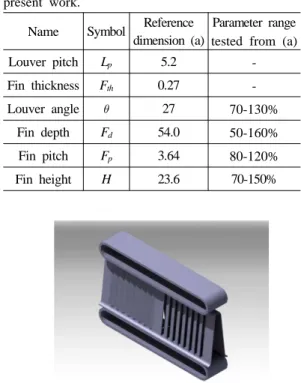
Table 1: Dimensions of louver fin-tube heat exchanger and range of parameters used in the present work.
Name Symbol Reference dimension (a)
Parameter range tested from (a)
Louver pitch L p 5.2 -
Fin thickness F th 0.27 -
Louver angle 27 70-130%
Fin depth F d 54.0 50-160%
Fin pitch F p 3.64 80-120%
Fin height H 23.6 70-150%
Figure 1: Brazed louver fin-tube heat exchanger used in transportation applications.
Figure 2: Schematic diagram of the louver fin-tube heat exchanger.
flat tube reduces the air-side flow resistance, and
provides a bigger area for heat transfer. The louver
fins also enhance the heat transfer by creating a
surface with many interruptions and accelerating the
air velocity. Figure 2 and the Table 1 show the
dimensions and range of parameters used in the
present work.
0.4 0.8 1.2 1.6 2.0
Ob je c tive fu nct ion , φ
0.4 0.6 0.8 1.0 1.2 1.4 1.6
Design parameter
w
Q=1.0, w
ΔP,air=0.0 Tube depth, Td Fin pitch, Fp Louver angle, θ Fin height, H
0.8 1.0 1.2 1.4 1.6
Obj e c ti v e fun c tio n , φ
0.4 0.6 0.8 1.0 1.2 1.4 1.6
Design parameter
w
Q=0.8, w
ΔP,air=0.2 Tube depth, Td Fin pitch, Fp Louver angle, θ Fin height, H
(a) w Q =1.0, w Δ P,air =0.0 (b) w Q =0.8, w Δ P,air =0.2
0.8 1.2 1.6 2.0 2.4
O bjec ti ve f unc tio n , φ
0.4 0.6 0.8 1.0 1.2 1.4 1.6
Design parameter
w
Q=0.5, w
ΔP,air=0.5 Tube depth, Td Fin pitch, Fp Louver angle, θ Fin height, H
0.0 1.0 2.0 3.0 4.0 5.0
Obje c ti v e fu ncti on, φ
0.4 0.6 0.8 1.0 1.2 1.4 1.6
Design parameter
w
Q=0.0, w
ΔP,air=1.0 Tube depth, Td Fin pitch, Fp Louver angle, θ Fin height, H
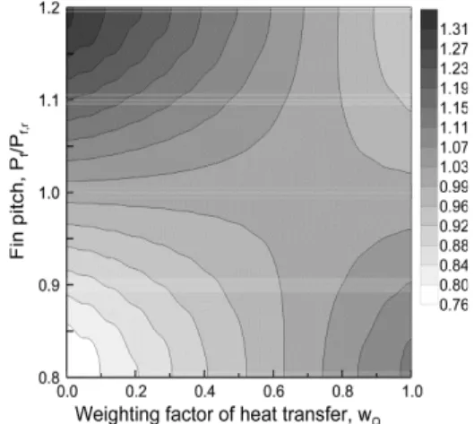
(c) w Q =0.5, w Δ P,air =0.5 (d) w Q =0.0, w Δ P,air =1.0 Figure 3: Sensitivity of the design parameters in the present work.
3. Optimization Method
3.1 Objective Function and Design Parameters
The objective function in the present work is a combination of pressure drop and heat transfer rate as expressed below: [9]
(1)
where w Q , w △P,air , a and b are the weighting factors and exponents to normalize the heat transfer rate and pressure drop by their reference values respectively. The reference heat transfer rate and pressure drop are for the reference heat
exchanger, and their geometric data are listed in Table 1. High heat transfer and low pressure drop are favorable, so exponents a and b have different signs. The heat transfer rate is less sensitive than the pressure drop, so the absolute value of a is greater than that of b. The exponents a and b were set as 0.5 and -2, respectively in the present work.
3.2 Heat Exchanger Performance
The performance of the louver fin-tube heat
exchanger can be calculated by the following
procedure. The pressure drop and heat transfer rate
are for the air side:
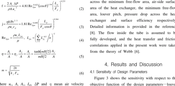
(a) w Q =1.0, w Δ P,air =0.0 (b) w Q =0.8, w Δ P,air =0.2
(c) w Q =0.5, w Δ P,air =0.5 (d) w Q =0.0, w Δ P,air =1.0
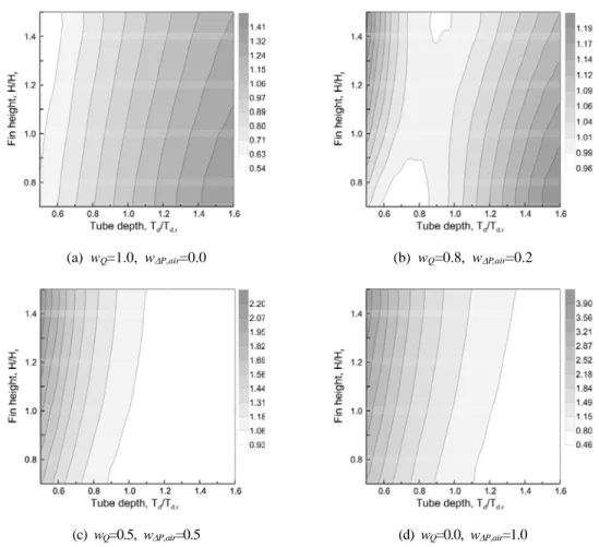
Figure 4: Contour maps of the objective function for tube depth and fin pitch when the louver angle and fin height are reference values in Table 1.
( )
0.233 1.94 622 - 0
2
4 . 81 Re cos
f 2 ⎟ ⎟
⎠
⎞
⎜ ⎜
⎝
= ⎛
= Δ
p . p
- Lpa c
c
F L u
A P
A θ
ρ (2)
0.364 698
. 0 3
/ 2
Re cos 81 . Pr 1
j ⎟ ⎟
⎠
⎞
⎜ ⎜
⎝
= ⎛
=
−θ ρ
η
p p Lpa p
c
F
L c
u h
(3)
2
1 5 .
0
, Re
−
=
−
⎟
⎠
⎜ ⎞
⎝
= ⎛
= u L L ∑
nL n
i p pa pa c
Lpa
μ
iρ
(4)
( )
A A mH
mH A
A A A A
A f t f
f t
2 2 + tanh
= +
= η
η (5)
th f