DESIGN ANALYSIS OF OFFSET STRIP FIN HEAT EXCHANGER
Himangshu Bhowmik
a,†Kwan-Soo Lee
a aSchool of Mechanical Engineering, Hanyang University 17 Haengdang-dong, Seongdong-gu, Seoul, 133-791, Korea
Abstract
The characteristics of heat transfer and pressure drop in an offset strip fin heat exchanger was studied with a steady-state three dimensional numerical model. Flow Reynolds number Redh ranged from10 to 3500 and Prandtl number Pr ranged from 0.7 to 50. The dimensionless performance factors, i.e. ‘the pumping power factor F’ and ‘the heat transfer performance factor J’ were analyzed and obtained a relationship between them. Finally, the prediction of F and J factors was generalized for different Prandtl numbers.
INTRODUCTION
To reduce the size and weight of heat exchanger, offset strip fin geometry can be employed. The offset strip fins are especially suitable for removing heat from high temperature fluids. Due to the high surface compactness of offset strip fin, the enhancement of heat transfer is also accompanied by an increase in pressure drop. Kays and London [1] carried out an experimental analysis and developed correlations for f and j factors for air. Weiting [2] reported correlations for laminar and turbulent flow regimes for air. Joshi and Webb [3] identified the transition region and modified the Weiting’s [2] correlations. Mochizuki [4] reexamined the Weiting’s [2] correlations and made some modifications to coefficients and exponents to fit their experimental data. Manglik and Bergles [5] reviewed the literature and provided the correlations of the f and j factors in the laminar and turbulent regions. The results presented in the literature [1-5] have not been validated for fluids with a high Prandtl number. For water and engine oil, Tinaut et al. [6] developed a model and analyzed the heat exchanger performance for different Prandtl numbers. Hu and Herold [7,8] investigated experimentally and numerically the effect of Prandtl number and observed a little effect on the f and a significant effect on the j factor. In the above mentioned studies, the attention was only focused on design evaluation problems or optimization through theoretical or experimental methods. For practical applications, Lahaye et al. [9] presented relevant fluid flow and heat transfer data with the dimensionless performance plot between a ‘pumping power factor F’ and a ‘heat transfer performance factor J’ (but not generalized the correlations for higher Prandtl number). This provides motivations of the present analysis.
The objective of the present study is to derive the relationship between the dimensionless performance factors, i.e. F and J, which can be used to obtain an effective thermal design of offset strip fin heat exchanger. The relationship between the F and J factors are also obtained for different Prandtl numbers to study the effect of Prandtl number.
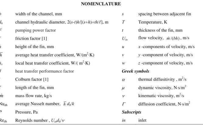
NOMENCLATURE
b width of the channel, mm s spacing between adjacent fin
dh channel hydraulic diameter, 2(s-t)h/[(s+h)+th/ℓ], m T Temperature, K
F pumping power factor t thickness of the fin, mm
f friction factor [1] Uin flow velocity, m&/(bh), m/s
h height of the fin, mm u x -components of velocity, m/s h average heat transfer coefficient, W/(m2⋅K) v y -component of velocity, m/s
hx local heat transfer coefficient, W/( m2⋅K) w z -component of velocity, m/s
J heat transfer performance factor Greek symbols
j Colburn factor [1] α thermal diffusitivity , m2/s
ℓ length of the fin, mm μ dynamic viscosity, N⋅s/m2
m& mass flow rate, kg/s ν kinematic viscosity, m2/s
Nudh average Nusselt number, hdh/k Γ diffusion coefficient, N⋅s/m2
P Pressure, Pa Subscripts
Redh Reynolds number , Uindh/ν in inlet
DESCRIPTION OF THE PROBLEM AND GEOMETRY
Offset strip fin heat exchanger dimensions
The offset strip fins were arrayed in the flow direction, as shown in Fig. 1. The baseline design consisted of 20 fins. Their surface geometry was described by the fin length ℓ, height h, transverse spacing s, and thickness t, or by three dimensionless parameters α = s/h, δ = t/ℓ, and γ = t/s as α = 1, δ = γ = 0.167. The fins were uniformly offset by half the fin spacing and designed to be of equal size and shape to maintain the geometric periodicity. The hydrodynamic entrance length was chosen to be 20 mm, so that the flow was already fully developed at the fins.
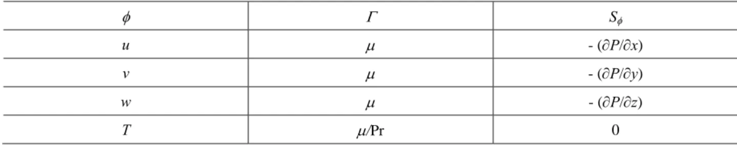
Table 1 General variables and corresponding diffusion coefficients and source terms φ Γ Sφ u μ - (∂P/∂x) v μ - (∂P/∂y) w μ - (∂P/∂z) T μ/Pr 0
Modeling approach and governing equations
The fluid flow inside the heat exchanger channel was considered to be incompressible and steady. The heat exchanger channel was characterized by the presence of the rectangular offset strip fins, mounted in a staggered fashion along the flow direction, as shown in Fig. 1. FLUENT Version 6.2 [10], a CFD software based on a finite-volume method, was employed to solve the fluid flow and heat transfer problems. The preprocessor GAMBIT was used to create a computational mesh. The finite volume technique and the semi-implicit method for pressure-linked equation (SIMPLE) were used to solve the basic conservation Eqs. (1) and (2).
The continuity equation:
( ) ( ) ( )=0 ∂ ∂ + ∂ ∂ + ∂ ∂ z w y v x u ρ ρ ρ (1)
The convection-diffusions equation:
( ) ( ) ( ) . φ φ φ φ φ ρ φ ρ φ ρ S z Γ z y Γ y x Γ x z w y v x u + ⎟ ⎠ ⎞ ⎜ ⎝ ⎛ ∂ ∂ ∂ ∂ + ⎟⎟ ⎠ ⎞ ⎜⎜ ⎝ ⎛ ∂ ∂ ∂ ∂ + ⎟ ⎠ ⎞ ⎜ ⎝ ⎛ ∂ ∂ ∂ ∂ = ∂ ∂ + ∂ ∂ + ∂ ∂ (2)
In Eq. (2), Sφ is the source term; the general variable φ represents u, v, w, or T; and Γ represents the appropriate
transport coefficient, as given in Table 1.
Boundary conditions and Grid independence
A constant mass flow rate was set for the inlet boundary condition, and constant pressure for the outlet. In the stream wise direction (z-axis), the translationally periodic boundary conditions were specified. FLUENT treated the flow at a periodic boundary as though the opposing periodic plane was a direct neighbor of the cells adjacent to the first periodic boundary. Aluminum was specified as the solid material for the fins. At the fin walls, constant temperature boundary condition was used. Fluid properties such as density, thermal conductivity, viscosity, and specific heat capacity were also specified.
RESULTS AND ANALYSES Model validation
To test the validity of the present numerical model, data collected from Hu and Herold [7] for water, Joshi and Webb [3] and Manglik and Bergles [5] for air are plotted in Fig. 2 for the f and j factors. The deviations of our results from the cited results are within a range of 10–20%. Hu and Herold [7] performed their analysis for water, under conditions similar to ours, and hence our date agrees reasonably well with their results. A change in slope appeared as shown in Fig. 2 (for f factor) indicating a change in the flow and heat transfer regions, i.e. from laminar to turbulent. Even though the curves for air [3,5] were not close to our results, they were of similar slopes both.
As could be seen in Fig. 2, the present friction factor, f data for air and water were very close. Hu and Herold [7] also did not observe any deviation for friction factor, even the Prandtl number ranged from 0.7 to 150. However, our model was definitely able to reproduce their results qualitatively, as will be described in the following sections. Comparison of results obtained from the air models to our own findings demonstrated that air-based analysis is inappropriate for application to liquid media. The difference is due to the effects of the Prandtl number. From the definition of the Colburn factor j, a large value of Pr was expected to give a lower j value for constant Reynolds and Nusselt numbers. In the actual comparison, the Colburn factor j for water was about twice that for air with the same Reynolds number, as conjectured from the definition of j factor; viz. (Prwater/Prair)1/3 = (7/0.7)1/3 = 2.15. In Fig 2, the friction factor f was not influenced by the Prandtl number, as the proximity of the data for air and water, but the Colburn factor j data for water were over predicted compared to the Colburn factor for air. However, in an offset strip fin heat exchanger, the Prandtl number has been found to have a small effect on the friction factor and a significant effect on the Colburn factor.
Design analysis
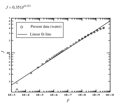
For practical application, LaHaye et al. [9] presented fluid flow and heat transfer data with a dimensionless performance plot between a “heat transfer performance factor J” and a “pumping power factor F”. The F and J factors can be defined as F = fRedh3 and J = jRedh, respectively. The coefficient C and exponent m of Eq. (3) can be obtained by linear fit method, and the results are shown in Fig. 3, and in Eq. (4). This analysis might be regarded as the more powerful presentation of the performance of offset strip fins than the previous f and j plot in Fig. 2. The C and m values of Eq. (3) are obtained for the liquid (Pr = 7), and can be shown in Fig. 4.
J = CFm
(3)
J = 0.351F0.223
(4)
Figure 3- General correlation for heat transfer and friction factor data
Figure 4- Variations of C and m with Prandtl number
1E+3 1E+4 1E+5 1E+6 1E+7 1E+8 1E+9 1E+10
2 3 4 5 6 7 8 9 2 3 4 5 6 7 10 F J
Present data (water) Linear fit line
Effects of Prandtl number
It was found in the literature that the thermal field of offset strip fin was strongly influenced by Reynolds and Prandtl numbers. Therefore, the Prandtl number has been found to have a significant effect on the performances of an offset strip fin heat exchanger. To study the heat transfer characteristics of different fluids, namely different Prandtl number, the value of C and m in Eq. (3) can be obtained for different fluids (Pr = 0.7 to 50). The variations of C and m values with Pr are shown in Fig. 4. It is seen from Fig. 4 that the variations of C and m are not very significant at the value of Pr larger than 35. Therefore, this figure can also be used as a design plot with different fluids.
CONCLUSIONS
A steady state three dimensional analysis of offset strip fin heat exchanger was performed. The model described the effect of fluid flow and heat transfer at the Reynolds and Prandtl numbers ranging from 10 to 3500 and 0.7 to 50, respectively. The dimensionless performance factors, i.e. F and J were analyzed and obtained the correlation Eq. (4). The correlations were also obtained for different Prandtl number that can be used to select the operating fluid for an offset strip fin heat exchanger.
REFERENCES
[1] Kays, W.M., London, A.L., Compact Heat Exchangers. (3rd edn., McGraw-Hill, NY, 1984).
[2] Weiting, A.R., “Empirical correlation for heat transfer and flow friction characteristics of rectangular offset-strip plate-fin heat exchangers,” J. Heat Tran., 97(3), 488-490 (1975).
[3] Joshi, H.M., Webb, R.L., “Heat transfer and friction in the offset strip fin heat exchangers,” Int. J. Heat Mass Tran., 30, 69-84 (1987).
[4] Mochizuki, S., Yagi, Y., “Transport phenomena in stacks of interrupt parallel-plate surface,” Exp. Heat Tran., 1, 127-140 (1987).
[5] Manglik, R.M., Bergles, A.E., “Heat transfer and pressure drop correlations for the rectangular offset strip fin compact heat exchanger,” Exp. Thermal Fluid Sci., 10 (2), 171-180 (1995).
[6] Tinaut, F.V., Melgar, A., Rahman Ali, A.A., “Correlations for heat transfer and flow friction characteristics of compact plate-type heat exchangers,” Int. J. Heat Mass Tran., 35(7), 1659-1665 (1992).
[7] Hu, S., Herold, K.E., “Prandtl number effect on offset fin heat exchanger performance: predictive model for heat transfer and pressure drop,” Int. J. Heat Mass Tran., 38 (6), 1043-1051 (1995).
[8] Hu, S., Herold, K.E., “Prandtl number effect on offset fin heat exchanger performance: experimental result,” Int. J. Heat Mass Tran., 38 (6), 1053-1061 (1995).
[9] LaHaye, P.G., Neugebauer, F.J., Sakhuja, R.K., “A generalized prediction of heat transfer surfaces,” ASME J. Heat Tran., 96 511-517 (1974).