c cc
2015 The Korean Academy of Prosthodontics
This is an Open Access article distributed under the terms of the Creative Commons Attribution Non-Commercial License (http://creativecommons.org/licens- es/by-nc/3.0) which permits unrestricted non-commercial use, distribution, and reproduction in any medium, provided the original work is properly cited.
*Corresponding Author: Ji-Man Park
Department of Prosthodontics and Detnal Research Institute, Seoul National University Gwanak Dental Hospital, 1 Gwanak-ro, Gwanak-gu, Seoul 151-742, Republic of Korea +82 2 6747 6114: e-mail, [email protected]
Article history: Received June 3, 2015 / Last Revision July 6, 2015 / Accepted July 8, 2015
Introduction
Computer-guided surgery (CGS) is a method that allows to plan ahead the position of the implant placement before surgery by considering the condition of the patient’s residual alveolar bone and the shape of the final prosthesis, and to place the implant corre- spondingly. It has been reported that the implant placed at the planned position satisfied aesthetics, proper occlusal relationship and hygienic requirements in fabricating the final prosthesis.1,2 The fabrication method of the template for computer-guided surgery can be largely classified into the “design-related rapid prototyping (RP)”and the “vector milling based on the coordinate synchro- nization”. In the former method, the implant guide itself is made using resin by 3D printing and metal bushings are fixed afterwards, while in the latter method, a plaster cast is processed by a milling
machine and subsequently metal bushings are fixed by applying resin directly.3In a previous study, it was reported that the accuracy of the vector milling method was higher than that of the design-related pro- cessing.4
In the design-related RP system, RP printing of the tissue surface of a surgical guide is performed on the basis of CT image of a radi- ographic template after double CT scanning is performed on the patient and radiographic template, and this method has a limitation of a low- er intraoral fit due to the resolution of CT. On the other hand, in the coordinate synchronization-based milling system, since the plaster cast is processed by synchronizing the coordinates of the implant planned on the program with a milling machine after the superposition of CT data of the patient and plaster cast, and the surgical template is fabricated using orthodontic resin after metal bushings are sub- sequently fixed in the upper part of processed holes, intraoral fit is
A case report of a surgical guide fabricated via intraoral scanning-based implant planning and wax-based rapid prototyping
Jong-Hoon Shin1, Eun-Jin Park1, Ji-Man Park2*
1Department of Prosthodontics, School of Medicine, Ewha Womans University, Seoul, Republic of Korea
2Department of Prosthodontics and Dental Research Institute, Seoul National University Gwanak Dental Hospital, Seoul, Republic of Korea
With the recent progress of digital technology, the computer guided surgery utilizing a guide template in the placement of implant has been actively performed, and the method employing the intraoral scanner at the implant prosthesis introduced. Fabrication method of the guide template can be largely classified into design-related rapid prototyping (RP) system and vector milling system, and each of the method has its own weakness in the clinical application despite of excellent accuracy. Thus, in this case study, a work- ing model was fabricated by the wax RP technology using images acquired by CBCT and an intraoral scanner, and the metal bushing was picked up with orthodontic resin cast upon the wax model. Using this method, a surgical guide template was fabricated and used in surgery. From this, we could obtain a satisfactory outcome clinically in the implant placement and the fabrication of the final prostheses and thus report this case herein. (J Korean Acad Prosthodont 2015;53:244-9)
Key words: Surgical guide; Intraoral scanning-based implant planning; Wax-based rapid prototyping
※This research was supported by Basic Science Research Program through the National Research Foundation of Korea (NRF) funded by the Ministry of Science, ICT & Future Planning (NRF- 2013R1A1A1076022).
high during the operation although fabrication process is complicated.5 RP system has increased the work efficiency by reducing the com- munication time between the designer and engineer in many indus- tries. Moreover, it was shown recently that not only a test prototype could be produced but also a mold could be fabricated using this sys- tem, which has therefore drawn more attention. Also, with the intro- duction of an additional function of adding color, RP system is uti- lized actively in the areas of civil engineering and landscaping as well as the conventional areas including medicine, art, vehicle design and clothing design. Particularly in the area of art, wax print- ing is mostly used in the manufacture of gold jewelry. In this study, a wax model containing a structure to fix metal bushings accord- ing to the position of the implant set on implant planning software was made by rapid prototyping and applied to the fabrication of a guide.
Recently, with the accelerated application of digital technology in dentistry, various intraoral scanners that can acquire intraoral 3 dimensional images without impression taking using impression mate- rial and the model fabrication processes have been introduced, and it has been reported that their accuracy could rival that of the con- ventional method in the case of not only a single tooth but also the full arch impression.6,7Therefore, by using such intraoral scanners instead of the CT data of a plaster cast, a surgical guide with an improved intraoral fit can be fabricated without the conventional impres- sion taking.
In this case, an implant surgery planning was performed using dig- ital impression data acquired by an intraoral scanner without the fab- rication of a radiographic template and CT double scanning, and a working model was fabricated using wax as material by rapid prototyping according to the plan. Subsequently, by picking up met- al bushings at exact positions of the model using orthodontic resin, the surgical guide template was fabricated and applied to surgery.
As we fabricated a surgical guide by the coordinate synchronization based method through CBCT and an intraoral scanner, and could obtain a satisfactory outcome in the placement of the implant in the application to surgery, we report the case.
Case report
A 52 year old male patient presented for the prosthetic restoration for left mandibular posterior missing teeth. The patient did not have a history of any particular systemic disease. After clinical and radiographic examinations, the placement of #35i, 36i and 37i implants, and the fixed implant prosthetic treatment were planned.
CBCT scanning was performed to evaluate the residual alveolar bone at the site of the implant placement, and digital impression was tak- en using an intraoral scanner (iTero; Align Technology Inc., San
Jose, CA, USA). DICOM data acquired by CBCT (Dinnova 3;
HDX, Seoul, Korea) was converted into the STL file on the implant planning software (Deltacian; EZplant, Seoul, Korea), which was superposed with the STL file of the intraoral scanner by a best fit algorithm. Then, the diameter, length, placement location and direction of the implant were determined on the virtual space in consideration of the amount of residual alveolar bone and the dis- tance to mandibular canal (Fig. 1. A-C).
Cylinder-shaped features to fix metal bushings were made at the positions, 4 mm from the top of the planned implant, where metal bushings would be placed. These data were exported in the format that allowed rapid prototyping, and transferred to the center.
Subsequently, these were 3D printed with a rapid prototyping machine (ProjetTMCPX 3000; 3D systems, Rock Hill, SC, USA) using a wax material (VisiJet M3 Hi-cart; 3D systems, Rock Hill, SC, USA), of which burnout was possible. On the wax model, metal bushings were fixed at the cylinder-shaped features, followed by blockout and resin pouring (Ortho-JetTMPackage; Lang Dental Manufacturing Co., Inc., Wheeling, WV, USA). Finally, a surgical stent was completed after removal from wax model by softening it under hot water and using steam (Fig. 1. D-H).
Using the fabricated computer-guided template, implants (USII 4.0×11.5 mm, 4.0×11.5 mm, 4.0×10 mm; Osstem, Seoul, Korea) were placed at positions #35i, 36i and 37i. Since it was fab- ricated on the basis of the scan data from intraoral scanner displaying accuracy with an error less than 35 ㎛, the guide was fixed stably and functioned during surgery although this was not a case of edentulous jaw using anchor pins (Fig. 1I).
Upon confirming stable osseointegration 4 months after surgery, digital impression was taken using an intraoral scanner (iTero;
Align Technology Inc., San Jose, CA, USA) and impression coping (Scanbody; DIO implant, Busan, Korea). Acquired data were sent to Cadent, Inc., and the processed STL data were forwarded to a milling center (Dio implant, Busan, Korea), where a model for the fabrication of a customized abutment and superstructure was designed using spe- cialized CAD software (DentCAD; Delcam, Salt Lake City, UT, USA), and subsequently the master model made of polyurethane resin and the customized abutment made of titanium were fabricated using a specialized milling machine (DentMILL; Delcam, Salt Lake City, UT, USA). By direct wax-up and cast on the polyurethane model, cement-retained gold crown was fabricated and delivered for the sec- ond molar while porcelain-fused-to-gold bridge of the screw- retained-after-cementation (SCRP) type were fabricated and deliv- ered for the two preceding teeth, i.e. second premolar and first molar.
The prosthetic treatment was completed 7 months after the place- ment of the implant, and the patient showed a satisfaction with aes- thetic and functional outcomes (Fig. 2).
Fig. 1. Surgical template fabrication and implant placement. (A) Initial panoramic X-ray. (B) Analysis by CBCT. (C) CBCT image (DCM format) and intraoral scan data (STL format) were superimposed by a best fit algorithm. (C) Planned implant location information and normal anatomic structure were printed into wax model by rapid prototyping machine. (D) Fabricated wax-based RP model. (E) Guide bushings were placed onto the planned position. (F) Block out was made before the application of framework material. (G) Resin pouring. (H) Completed surgical template. (I) Template was tried in the patient's mouth. Drilling and implant placement was performed through the metal bushings.
A B C
D E F G
H I
Fig. 2. Superstructure fabrication and delivery. (A) Scan bodies were connected and digital intraoral scanning was performed. (B) Customized abutment and working mod- el for final restoration were designed with CAD software. (C) Master model made of polyurethane resin. (D) Customized abutments were tried in the patient's mouth. (E) Intraoral photos after superstructure delivery. (F) Final panoramic X-ray.
A B C D
E
F
Accuracy analysis
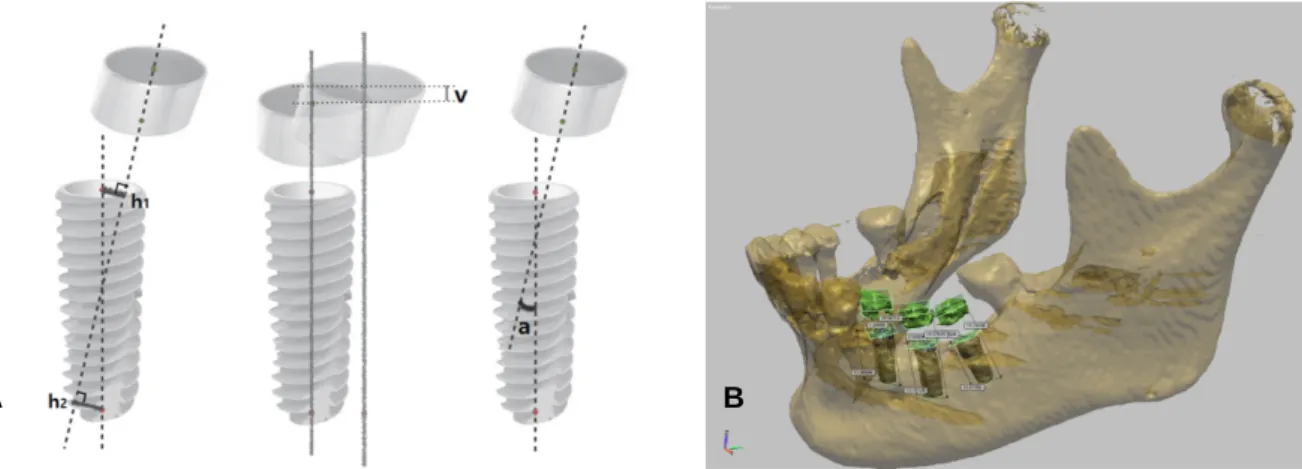
To analyze the accuracy of stent, CBCT scanning was per- formed on the patient with existing guide template on after the place- ment of implants under his consent. Deviations in horizontal and ver- tical distances, and angles between metal bushings and implants were measured on reverse engineering software (SolidWorks; Dassault Systems, Waltham, MA, USA). Measured horizontal, vertical error and angular errors were 1.56 ± 0.51 mm, 0.87 ± 0.10 mm and 4.99
± 3.19 degrees, respectively (Fig. 3, Table 1).
Discussion
Compared to the conventional method using periapical x-ray, panora- ma and plaster cast, computer-guided surgery is more effective in obtaining the ideal position for the implant, and thus placed implant displays a higher survival rate.8,9Also, the practitioner may feel sta- ble during surgery owing to the use of a guide, thereby giving a patient a satisfaction and less pain.10Since the outline of soft tissue cannot be reproduced only with CBCT data in the fabrication of an implant surgical guide, additional efforts to complement this are need- ed. In the RP system, the outline of the tissue surface of resin made after additional CT scanning of the oral cavity with the radi- ographic template or existing denture is replicated, and this is used as an inner surface of the guide. Thus, since the fit between the guide and tissue surface is poor due to the limitation in the resolution of CT, the stability and accuracy during surgery are unsatisfactory.
In contrast, since the guide is fabricated by directly applying resin on a model in the vector milling system, a higher fit can be expected.
In the existing vector milling system, after a fiducial marker is attached to the tooth surface of a patient or a titanium fixture is fixed
in alveolar bone, CT scanning and impression taking are per- formed, and subsequently a plaster cast is fabricated. Then, with a reference to the maker as a common element, patient CT data and plaster cast CT data are accurately matched. In contrast, in this case, a fiducial marker was not used while instead it was attempt- ed that the CT data and intraoral scanner data were matched using the best fit algorithm of the software. The reason for not using a mark- er is because it was considered that the resolution of intraoral scanning data was higher than that of the cast CT data, and thus the accuracy of the former was higher than that of the latter. If intrao- ral scanning that has relatively high resolution replaces additional CT scanning of the plaster cast in the vector milling system, an incon- venience of the fabrication of the plaster cast and additional CT scan- ning may be eliminated, and at the same time, a higher internal fit of a guide can be expected by replacing low resolution CT data.
In this case, by digital impression taking, the discomfort of a patient due to the use of impression material was eliminated, and since the storage and transport of impression body, and the fabrication of a plaster cast were omitted, their resulting errors could be avoided. Also, in this case, the data storage and re-use were easy, and much more convenient work was possible in the re-fabrication of prosthesis compared to the conventional method.11,12 In addition, Lee and Gallucci13suggested that digital impression taking was more effi- Fig. 3. Analysis of errors between vectors of objects.4(A) Method. (Left) Horizontal error (horizontal distance of the positions of bushings from those planned before surgery, average of h1and h2); (Center) Vertical error (vertical distance of the positions of bushings from those planned before surgery, v); (Right) Angular error (an angle between a bushing and a stopping, a). (B) Accuracy analysis was done by reverse engineering software.
A B
Table 1. Deviations between surgical guide bushings and placed implants from pre- and post-op CBCT data
Mean±SD Maximum deiviation
Horizontal error (mm) 1.56±0.51 1.89
Vertical error (mm) 0.87±0.10 0.93
Angular error (mm) 4.99±3.19 7.49
cient in terms of the preparation time, working time and impression re-taking time than the conventional method, and the evaluation of the difficulty in implant impression taking through visual analog scale was easier with digital method. There have been many studies on the accuracy of the intraoral scanner (iTero) used in this case.
Kim et al.6compared a polyurethane model fabricated by milling process using the iTero scan data with the scan data of a conventional plaster cast using a table top scanner, and reported an error of 23.96 ㎛ that was comparable to the value obtained by the conventional method. Ender and Mehl7observed an error of 32.4 ㎛ in a full arch model using iTero, and suggested that it could be applied to the full arch scanning within the limitation of a laboratory research. Also, in this study, a surgical guide fabricated using this intraoral scanner displayed a clinically excellent intraoral fit, which was consis- tent with the previous results on the clinical applicability of intra- oral scanners.
Park et al.4fabricated surgical guides using two different meth- ods, the vector milling system and design-linked processing, and the accuracy of the two systems were compared by measuring the dis- tance and angle between metal bushings and cylinder on reverse engi- neering software. Horizontal, vertical and angular errors were 0.14 mm, 0.20 mm and 0.88 degrees in the vector milling system, respectively, and 0.74 mm, 0.53 mm and 3.24 degrees in the RP sys- tem, respectively. While these values from both systems were clinically acceptable, it was reported that the vector milling system displayed less errors. Although the guide template fabricated in this study had a better intraoral fit, its horizontal, vertical and angular errors were larger than those of previous studies. It is considered that match- ing the intraoral scan images with the CBCT images only by a best fit algorithm without using fiducial marker could be the cause for such errors. The reason of not using fiducial marker was that it was expected that the matching accuracy would be increased since the resolution of the intraoral scanner images was high. Thus, it will be possible to fabricate a guide template with a better accuracy if the matching process is conducted by applying the marker to the oral cavity of a patient likewise in the vector milling system.
Conclusion
In this case, a working model made of wax was fabricated by the rapid prototyping using the digital impression data, and the metal bushing was picked up with orthodontic resin cast upon the mod- el. Using this method, a surgical guide template was fabricated and used in surgery. From this, we could obtain a satisfactory clinical out- come. This process led to the reduction in CT scanning, and also the digital impression taking resulted in the reduction of the exposure of patients to radiation, and the treatment time. As a result, surgery
planning and the fabrication of a guide, and the fabrication of prosthesis after surgery could all be performed digitally.
ORCID
Jong-Hoon Shin http://orcid.org/0000-0002-6321-2268 Eun-Jin Park http://orcid.org/0000-0001-6383-449X Ji-Man Park http://orcid.org/0000-0003-0018-1166
References
1. Fortin T, Champleboux G, Bianchi S, Buatois H, Coudert JL.
Precision of transfer of preoperative planning for oral implants based on cone-beam CT-scan images through a robotic drilling machine. Clin Oral Implants Res 2002;13:651-6.
2. Scherer U, Stoetzer M, Ruecker M, Gellrich NC, von See C.
Template-guided vs. non-guided drilling in site preparation of den- tal implants. Clin Oral Investig 2014 Oct 30.
3. Park JM, Yi TK, Jung JK, Kim Y, Park EJ, Han CH, Koak JY, Kim SK, Heo SJ. Accuracy of 5-axis precision milling for guided surgical template. J Korean Acad Prosthodont 2010;48:
294-300.
4. Park JM, Yi TK, Koak JY, Kim SK, Park EJ, Heo SJ. Comparison of five-axis milling and rapid prototyping for implant surgical tem- plates. Int J Oral Maxillofac Implants 2014;29:374-83.
5. Fortin T, Champleboux G, Lormée J, Coudert JL. Precise den- tal implant placement in bone using surgical guides in con- junction with medical imaging techniques. J Oral Implantol 2000;26:300-3.
6. Kim SY, Kim MJ, Han JS, Yeo IS, Lim YJ, Kwon HB. Accuracy of dies captured by an intraoral digital impression system using parallel confocal imaging. Int J Prosthodont 2013;26:161-3.
7. Ender A, Mehl A. In-vitro evaluation of the accuracy of conventional and digital methods of obtaining full-arch dental impressions.
Quintessence Int 2015;46:9-17.
8. Talwar N, Chand P, Singh BP, Rao J, Pal US, Ram H. Evaluation of the efficacy of a prosthodontic stent in determining the position of dental implants. J Prosthodont 2012;21:42-7.
9. Valente F, Schiroli G, Sbrenna A. Accuracy of computer-aided oral implant surgery: a clinical and radiographic study. Int J Oral Maxillofac Implants 2009;24:234-42.
10. Youk SY, Lee JH, Park JM, Heo SJ, Roh HK, Park EJ, Shin IH.
A survey of the satisfaction of patients who have undergone im- plant surgery with and without employing a computer-guided im- plant surgical template. J Adv Prosthodont 2014;6:395-405.
11. Wismeijer D, Mans R, van Genuchten M, Reijers HA. Patients' preferences when comparing analogue implant impressions using a polyether impression material versus digital impressions (Intraoral Scan) of dental implants. Clin Oral Implants Res 2014;25:1113-8.
12. Logozzo S, Zanetti EM, Franceschini G, Kilpela A, Makynen A.
Recent advances in dental optics - Part I: 3D intraoral scanners for restorative dentistry. Opt Laser Eng 2014;54:203-21.
13. Lee SJ, Gallucci GO. Digital vs. conventional implant impressions:
efficiency outcomes. Clin Oral Implants Res 2013;24:111-5.
구강스캐너를 이용한 임플란트 수술 계획 및 왁스 기반 쾌속조형법으로 제작한 수술용 가이드 증례
신종훈1∙박은진1∙박지만2*
1이화여자대학교 의학전문대학원 치과보철학교실
2관악서울대학교치과병원 치과보철과
최근 디지털 기술이 발달하면서 임플란트 식립 시 가이드 템플릿을 이용하는 컴퓨터 가이드 수술이 활발하게 이루어지고 있으며, 임플란트 보철 시 구강스캐너를 이용하는 방법이 소개되고 있다. 가이드 템플릿의 제작방법은 크게 RP 제작 시스템과 벡터 밀링 시스템으로 나눌 수 있는데, 각각 은 우수한 정확성에도 불구하고 임상적 적용에 있어 약간의 아쉬운 점을 보이고 있다. 이에 본 증례에서는 CBCT 및 구강스캐너로 획득한 디지털 영상을 이용하여 쾌속조형법으로 왁스재료의 작업모형을 제작하고 그 위에 교정용 레진으로 금속애관을 픽업해 내는 방법을 사용하여 임플란트 수술용 가이드 템플릿을 제작하여 수술에 사용하였으며, 임상적으로 임플란트 식립 및 최종보철물 제작 시 만족스러운 결과를 얻을 수 있어서 이 를 보고하고자 한다. (대한치과보철학회지 2015;53:244-9)
주요단어: 수술용 가이드; 구강스캐너를 이용한 임플란트 수술계획; 왁스를 이용한 쾌속조형법
*교신저자: 박지만
151-742 서울 관악구 관악로 1 관악서울대학교치과병원 치과보철학교실 02-6747-6114: e-mail, [email protected]
원고접수일: 2015년 6월 3일 / 원고최종수정일: 2015년 7월 6일 / 원고채택일: 2015년 7월 8일
2015 대한치과보철학회
이 글은 크리에이티브 커먼즈 코리아 저작자표시-비영리 3.0 대한민국 라이선스에 따라 이용하실 수 있습니다.
c cc
※이 연구는 미래창조과학부 자금으로 한국연구재단의 기본연구자지원사업의 지원 하에 이루어졌습니다 (NRF- 2013R1A1A1076022).