381 https://doi.org/10.9713/kcer.2018.56.3.381
PISSN 0304-128X, EISSN 2233-9558
A Study of Upgrading Real Biogas via CO
2Precipitation Route Under Indian Scenario
Avneesh Kumar Gehlaut, Ankur Gaur†, Shabih Ul Hasan and Jin-WonPark*
Department of Chemical Engineering, Motilal Nehru National Institute of Technology, Allahabad-211004, Uttar Pradesh, India.
*Department of Chemical and Biomolecular Engineering, Yonsei University, , 50, Yonsei-ro, Seodaemun-gu, Seoul, 03722, Korea.
(Received 25 September 2017; Received in revised form 21 February 2018; accepted 8 March 2018)
Abstract − Our study focuses on upgrading real biogas obtained under Indian scenario using carbon capture and uti- lization (CCU) technology to remove carbon dioxide (CO2) and utilize it by forming metal carbonate. Amines such as monoethanolamine (MEA), diethanolamine (DEA), and sodium hydroxide (NaOH) were used to rapidly convert gas- eous CO2 to aqueous CO2, and BaCl2 was used as an additive to react with the aqueous CO2 and rapidly precipitating the aqueous CO2. All experiments were conducted at 25 ºC and 1 atm. We analyzed the characteristics of the BaCO3 precipi- tates using X-ray diffractometry (XRD), scanning electron microscopy - Energy dispersive spectroscopy (SEM-EDS) and Fourier-transform infrared spectroscopy (FT-IR) analyses. The precipitates exhibited witherite morphology con- firmed by the XRD results, and FT-IR confirmed that the metal salt formed was BaCO3, and EDS showed that there were no traces of impurities present in it. The quantity of the BaCO3 was larger when formed with DEA. Also, a com- parison was done with a previous study of ours conducted in Korean conditions. Finally, we observed that the carbonate obtained using real biogas showed similar properties to carbonates available in the market. An economic analysis was done to show the cost effectiveness of the method employed by us.
Key words: Barium carbonate, Biogas, Precipitation, Methane, amines, Carbon dioxide
1. Introduction
Millions of dollars are invested in the generation of energy from the fossil fuels, and day by day fossil fuel supply is decreasing, so there is need for renewable sources of energy like biogas, wind, tidal and solar energy etc. Biogas production from waste biomass is one of the best mature renewable technologies present in the market [2- 3] Biogas generation from the waste provides two simultaneous solutions to solid waste management and energy generation, which is favored by the current Swach Bharat policy of Indian Govern- ment. Biogas is mainly produced by the anaerobic digestion of bio- mass. Various designs of anaerobic digesters models like fixed and floating dome type digesters are used widely, but fthe loating type digester has gained much attention toward biogas generation due to ease of maintenance [4]. Biogas enhancement includes removal of CO2 and other impurities like hydrogen sulfide, traces of ammonia and water vapor. Carbon dioxide capture and utilization (CCU) is one of the best ways to capture the CO2 produced from biogas.
Absorption process is one of the most common techniques for CO2 removal. In the present scenario, one of the most effective methods for the uptake of CO2 is the chemical absorption process, which usu- ally employs aqueous solutions like amines, ammonia water and adsorption. The use of amines has certain disadvantage too, like cor- rosion and loss of amines dues to volatile nature [20]. Ammonia
water is also preferred over conventional amine absorbent due to high CO2 loading [19]. Simultaneous removal of SOx and NOx along with CO2 using amines makes the chemical absorption process more efficient [16]. DEA shows a higher CO2 loading rate as compared to MEA [17]. A very high penalty cost is attached with the amine pro- cess for CO2 capture from coal-fired plants [18]. Chemical absorption technique requires a huge amount of energy during the desorption step, which makes CO2 capture uneconomical. To counter this prob- lem, an effort was undertaken to convert CO2 into solid carbonates [9]. In previous study, landfill gas was used in Korean conditions and CO2 was successfully converted to carbonates [8-11]. This paper focuses on using a process similar to the earlier study, but the input gas is real biogas and pure CO2. We have considered the Indian sce- nario instead of landfill gas. The data obtained during the present study is better than in the previous study [9]. The amount of carbonates formed is higher. Previous study [9] was just a technical note, so some technical and economic data are not mentioned. However, in the cur- rent study technical data such as biogas production rate, characteri- zation of carbonates formed using techniques such as FTIR, XRD and SEM-EDX is covered. Also, economic analysis was done to show how converting CO2 to carbonate makes the traditional CO2 capture process profitable, which has not been discussed in literature till date. This technique really suits the Indian scenario and can make biogas plants a profitable venture.
2. Experimental 2-1. Materials
All the chemicals, such as MEA, DEA and NaOH, were pur-
†To whom correspondence should be addressed.
E-mail: [email protected]
This is an Open-Access article distributed under the terms of the Creative Com- mons Attribution Non-Commercial License (http://creativecommons.org/licenses/by- nc/3.0) which permits unrestricted non-commercial use, distribution, and reproduc- tion in any medium, provided the original work is properly cited.
chased from CDH (purity: >99%). Deionized water was used for solution preparation. All chemicals were of analytical grade and used as received without further purification. Fresh cow dung and water were obtained from the Narayani Ashram, Allahabad.
2-2. Absorption of CO2
In the precipitation experiment we used 50 grams of BaCl2 dis- solved in water with additives like amines and NaOH. The first step involved saturation of the amine and BaCl2 solution with biogas and pure CO2 gas. Each amine was diluted to a different concentration with balance deionized water. The CO2 absorption reactor was filled with 1 Liter solution of BaCl2 and amines. We maintained the tem- perature at 25º C and 1 atm pressure. The biogas was passed into the absorption reactor and outlet/inlet gas was evaluated using CO2 ana-
lyzer of different intervals after reacting with the amine solution.
The entire process was conducted for 1 h. Then, we separated the liquid and solid by filtration through filter paper. In addition, we used gas chromatography to measure the initial and final biogas composition.
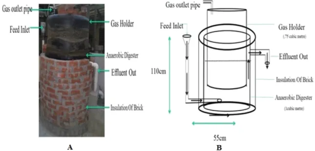
The reactions of primary and secondary amines with CO2 CO2 + R1R2NH ↔ R1R2NH+CO2- (1) R1R2NH+ CO2- + R1R2NH ↔ R1R2NH2+ + R1R2NCO2- (2) R1R2NH+ CO2- + H2O ↔ H3O + R1R2N CO2- (3) 2RNH2 + CO2 ↔ RNH CO2- RNH3+ (4) RNHCO2RNH3 ↔ RNH3HCO3 + RNH2 (5) RNH3HCO3 + RNH2 ↔ 2RNH3CO32- (6) 2RNH3 CO32-+ BaCl2 ↔ 2RNH3 2Cl- + BaCO3 (7) Fig. 1. A. Anaerobic digester setup used during this study B. Exact dimensions of anaerobic digester.
Fig. 2. Schematic diagram of carbonation experimental apparatus.
2-3. Physical Characterization
The X-ray diffraction (XRD) patterns of the BaCO3 were recorded with Rigaku D/MAX-2400X-ray diffractometer system using a Cu Ka radiation (l ¼ 1.5406 Å) in the 2q range from 5º to 65º, operated at 40 mA and 40 kV, and a scanning speed of 10º Min-1. The FT-IR spectra were measured on an ATR FTIR spectrophotometer into the sample cell with a thickness of 0.005 mm between two KBr plates in the range of 4000- 400 cm-1. Surface morphology of the BaCO3 was analyzed using CARL ZEISS EVO 50 with resolution - 2.0 nm at 30 kV, acceleration Voltage-0.2 to 30 kV, magnification-5x to 1,000,000x, field of view-8.5 mm at the analytical working distance (AWD), X-ray analysis 8.5 mm AWD and 35° take-off angle; detectors used were SE in HV - Everhart-Thornley and BSD in all modes - quadrant semiconductor diode.
3. Results and Discussion
3-1. Biogas Production
The biogas was obtained from a real biogas plant situated in Narayani Ashram near our University. The photograph and dimensions of the real biogas plant are in Fig. 1. The gas holder volume was 0.75 m3; brick insulation of around 10 cm was done around anaerobic digester to maintain the temperature. The feed rate was around 5 kg per day.
Biogas was produced from cow dung over a period of 29 days and it increased gradually as mentioned in Fig. 3. Biogas production increased progressively after the 16th day. The biogas was analyzed using GC and it was mainly composed of CO2, CH4, H2S, water vapor and ammonia. The components of biogas are mentioned in Table 1.
Methane was present in the range 55-65 volume %. CO2 was present in the range 35-40%, and rest of the components were less than 5%.
Our analysis matched the references [5-7] as discussed in Table 2.
We used high quality silica gel before the biogas entered the reactor.
Silica gel effectively removed all the minor components present in the biogas. The biogas entering into the reactor mainly consisted of methane CH4 and CO2. The Indian subcontinent provides the ideal temperature for high quality methane production.
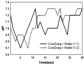
It was observed that the digester temperature fluctuated between 28 ºC and 35 ºC while the pH of the medium was between 6.5-7.2. In the anaerobic digestion the pH initially decreased to 6.6, and after the
thirteenth day pH was around 7, as displayed in Fig. 4. In biogas gen- eration, pH plays a vital role; if pH is decreased beyond 6 then no biogas is generated. The range of temperature and pH matched the reference data [5-7], as mentioned in Table 2.
Methanogens produce methane as a metabolic by-product in anaerobic conditions. They uniquely belong to the archaea kingdom, which are very pH sensitive, so it is mandatory to maintain the pH around 7 and temperature above 25 ºC.
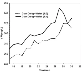
Volatile fatty acid (VFA) also plays a vital role in gas production;
as we can observe from Fig. 5 that cow-dung in 1:1 ratio mixtures with water gives a high VFA as compared to cow dung 1:2 ratio mix- ture. The VFA value obtained by us matched the VFA in references which used cow dung as a feed as mentioned in Table 2.
3-2. Carbonate formation
There are nine different types of prepared solutions which are marked as A, B, C, D, E, F, G, H and I. Solutions A, B and C consist of 1, 2 and 3 wt% NaOH, respectively; solutions D, E and F consist of 1, 2 and 3 wt% MEA, respectively; solutions G, H and I consist of 1, 2 and 3 wt% DEA, respectively. The pH of the final solution set- Table 1. Concentration of main components present in biogas
Main Components % content (% vol)
Current study Ref.
Methane (CH4) 55-65 55-70 [5]
Carbon Dioxide (CO2) 35-40 30-40 [5]
Hydrogen Sulfide (H2S)/
water vapor/Ammonia 0-5 0-5 [5]
Table 2. Comparison of parameters measured in anaerobic digester
Parameters Current study Ref.
VFA 240-350 350-550 [5-7]
pH 6.8-7.4 6.8-7.4 [5-7]
Temperature 25-45oC 0-35oC [5-7]
Fig. 3. Variation in biogas production using different ratio of cow- dung and water.
Fig. 4. Change in pH with respect to time (days) in anaerobic digester.
tled between 7~8 as mentioned in Table 3. Taking a cue from our previous work [9], we decided to take 50 g of Barium salt.
The amount of carbonates obtained from the alkaline solution is also displayed in increasing order D<G<A<E<H<F<B<I<C. In
Table 4 the amount of carbonate formed is displayed. Most of the solutions were neutralized after the precipitation reaction was over.
We can also observe in Table 5 that quantity of carbonates obtained during the current study is higher than in the previous study.
3-3. FTIR
FTIR characterization of the precipitated BaCO3 obtained by the absorption of CO2 was done. The result of the FTIR graph is shown in Fig. 6. The spectra are similar to the spectrum of pure BaCO3 which presents peaks primarily at k = 1428, 878 and 736 cm.
The BaCO3 salt obtained from pure CO2 and biogas showed increased absorbance at higher concentration, which was similar to characteristics of pure BaCO3. Similar peak was observed in [13].
Both the FTIR results showed that there is not much difference in property of barium carbonate obtained from different gas input.
3-4. XRD
The barium carbonate obtained using amines and BaCl2 was char- Fig. 5. Variation in between VFA and Time (days) for different ratio
of cow dung and water.
Table 3. Change in pH of different solutions before and after passing biogas
Solutions Initial pH Final pH
1 wt% NaOH + 50g BaCl2·2H2O (A) 12.89 7.93 2 wt% NaOH + 50g BaCl2·2H2O (B) 12.50 7.86 3 wt% NaOH + 50g BaCl2·2H2O (C) 12.10 7.62 1 wt% MEA + 50g BaCl2·2H2O (D) 12.82 7.52 2 wt% MEA + 50g BaCl2·2H2O (E) 12.03 7.13 3 wt% MEA + 50g BaCl2·2H2O (F) 11.16 7.16 1 wt% DEA + 50g BaCl2·2H2O (G) 13.20 7.80 2 wt% DEA + 50g BaCl2·2H2O (H) 12.72 7.60 3 wt% DEA + 50g BaCl2·2H2O (I) 12.03 7.03
Table 4. Amount of carbonates formed using biogas and pure CO2
Solutions Amount of carbonates formed (g[sorbent L]-1) (biogas)
Amount of carbonates formed (g[sorbent L]-1) (pure CO2)
1 wt% NaOH + 50g BaCl2·2H2O (A) 22.3 30
2 wt% NaOH + 50g BaCl2·2H2O (B) 36.6 40
3 wt% NaOH + 50g BaCl2·2H2O (C) 48.8 54.8
1 wt MEA + 50g BaCl2·2H2O (D) 12.7 24.1
2 wt% MEA + 50g BaCl2·2H2O (E) 26.2 34.2
3 wt% MEA + 50g BaCl2·2H2O (F) 36.3 43.2
1 wt% DEA + 50g BaCl2·2H2O (G) 16.6 24.7
2 wt% DEA + 50g BaCl2·2H2O (H) 28 36.1
3 wt% DEA + 50g BaCl2·2H2O (I) 39 45.6
Table 5. Comparison of current work with [9]
Solutions Amount of carbonates formed (g[sorbent L]-1) (Biogas)
Amount of carbonates formed (g[sorbent L]-1) (pure CO2)
[9] (g[sorbent L]-1) ( Landfill Gas)
5 wt% NaOH + 50g BaCl2·2H2O (J) 49 56 NA
5 wt% MEA + 50g BaCl2·2H2O (K) 40 48 34
5 wt% DEA + 50g BaCl2·2H2O (L) 42 49.2 35.90
Fig. 6. FTIR of BaCO3 obtained from pure CO2 and biogas.
acterized by XRD to determine its crystalline phase. As far as mor- phology is concerned, X-ray diffraction patterns were obtained in this study as shown in Fig. 7, which matched the one numbered 41- 0373 in JCPDS. From JCPDS we found that BaCO3 is orthorhom-
bic and withered. We found that the different carbonate structure is derived from the amine structures.
Increase in the amine concentration resulted in greater formation of crystalline structure and more stable compound. DEA provides Fig. 7. XRD graph of BaCO3 obtained from (A) pure CO2 and (B) Biogas.
Fig. 8. A and C- SEM of Barium carbonate obtained from pure CO2, B and D EDS of Barium carbonate obtained from biogas.
more stable BaCO3 as compared to the other amines due to more absorbance of CO2 ions and precipitation of aqueous CO2 in carbon- ate. Obtained BaCO3 was also compared to the other studies done by other researchers, and we found that similar peaks were obtained [8- 10]. The h,k,l value can be readily indexed as (110), (111), (002), (112), (220), (221), (132) and (113).
3-5. SEM-EDS of BaCO3
Fig. 8 shows the SEM micrograph of carbonate samples. BaCO3 obtained from BaCl2 had nanorod-like structure. As we can see, the graph obtained from the biogas provided more stable structure as compared to the pure CO2. When pure CO2 was used for the reaction, it provided less nanorod-type shape structure of BaCO3 [8]. In Fig. 8B the nanorods are of inferior quality as compared to Fig. 8A due to the presence of some impurities present in biogas, whereas pure CO2 provides sharper rods. Our barium carbonate SEM was compared to other studies, and we found similar data when conventional method was used for barium carbonate pro- duction. Similar images were obtained by other researchers [8].
For elemental analysis of the material, further EDS was per- formed. No traces of impurity were present. Our micrograph and EDS confirmed that it was similar to the pure BaCO3 obtained from other conventional methods. The main mineral was Ba. EDS of all samples is shown in Fig. 8. The entire spectrum shows simi- lar elements present in the barium carbonate: barium, carbon and oxygen. It was observed that BaCO3 formed by the biogas had more Barium as compared to the pure CO2. The main target of this research was to produce high quality barium carbonate which can be directly sold in the market. Nanorod BaCO3 has wide range of application even in fuel cells as an alkali-earth metal-carbonate- based catalyst [14].
3-6. Economics
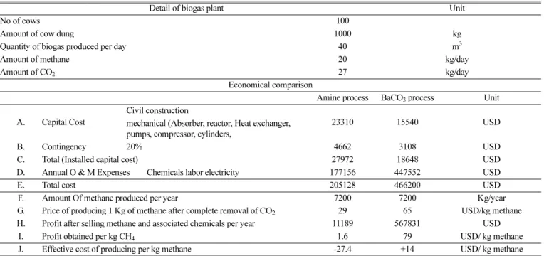
For calculating the economic feasibility of the process we consid- ered a biogas plant which can be fed with 1000 kg cow dung every day. Most of the dairy farms in India have around 100 cows, which can generate around 1000 kg cow dung, which produces around 20 kg of CH4 and 27 kg of CO2. The detailed economy comparison of MEA-based process and BaCO3 process is displayed in Table 6.
As we can observe from Table 6, using just amines for CO2 removal is not economical as we end up paying a penalty of 27.4 USD per kg of methane produced.
Using BaCO3 route we are able to make a profit of 14 USD per kg of methane produced, which makes the carbonate route an effective CO2 removal technology. Detailed economic analysis will be done in future studies.
According to the Indian standard, when using methane for auto- motive purposes the methane content should be minimum 90%, which we can easily obtain via the BaCO3 route for CO2 capture.
4. Conclusion
Carbonation method was used in purification of real biogas using amines and BaCl2. Barium carbonate formed by the carbonation method has wide use in the glass, ceramic and paint industries. From economical point of view, this process is very reliable and cost-effective as compared to other methods. The process is extremely economical and simple to scale up. The quality of methane obtained from this pro- cess is exceedingly high quality and it can be used in numerous processes.
References
1. Sorrell, S., Reducing Energy Demand: A Review of Issues, Chal- Table 6. Comparison of economics of amine and BaCO3 process
Detail of biogas plant Unit
No of cows 100
Amount of cow dung 1000 kg
Quantity of biogas produced per day 40 m3
Amount of methane 20 kg/day
Amount of CO2 27 kg/day
Economical comparison
Amine process BaCO3 process Unit
A. Capital Cost
Civil construction
23310 15540 USD
mechanical (Absorber, reactor, Heat exchanger, pumps, compressor, cylinders,
B. Contingency 20% 4662 3108 USD
C. Total (Installed capital cost) 27972 18648 USD
D. Annual O & M Expenses Chemicals labor electricity 177156 447552 USD
E. Total cost 205128 466200 USD
F. Amount Of methane produced per year 7200 7200 Kg/year
G. Price of producing 1 Kg of methane after complete removal of CO2 29 65 USD/kg methane H. Profit after selling methane and associated chemicals per year 11189 567831 USD
I. Profit obtained per kg CH4 1.6 79 USD/ kg methane
J. Effective cost of producing per kg methane -27.4 +14 USD/ kg methane
lenges and Approaches. Renew. Sustainable Energy Rev., 47, 74- 82(2015).
2. Cho, J. K., Park, S. C. and Chang, H. N., “Biochemical Methane Potential and Solid State Anaerobic Digestion of Korean Food Wastes,” Bioresour. Technol., 52, 245-53(1995).
3. Bundhoo, Z. M. A., Mauthoor, S. and Mohee, R., “Potential of Biogas Production from Biomass and Waste Materials in the Small Island Developing State of Mauritius,” Renew. Sustainable Energy Rev., 56, 1087-1100(2016).
4. Bond, T. and Templeton, M. R., “History and Future of Domestic Biogas Plants in the Developing World,” Energy Sustain. Dev.
15, 347-354(2011).
5. Miah, M. R., Rahman, A. K. M. L., Akanda, M. R., Pulak, A., and Rouf, M. A., “Production of Biogas from Poultry Litter Mixed with the co-substrate Cow Dung,” J. Taibah Univ. Sci., 10, 497- 504(2016).
6. Kim, D. J. and Kim, H., “Sludge Solubilization by Pre-treat- ment and its Effect on Methane Production and Sludge Reduction in Anaerobic Digestion,” Korean Chem. Eng. Res., 48(1), 103- 109(2010).
7. El-Mashad, H. M. and Zhang, R., “Biogas Production from Co- digestion of Dairy Manure and Food Waste,” Bioresoure. Technol., 101, 4021-4028(2010).
8. Gaur, A., Park, J. W. and Jung, J. H., “Metal-Carbonate Formation from Ammonia Solution by Addition of Metal Salts - An Effective Method for CO2 Capture from Landfill Gas (LFG),” Fuel Pro- cess. Technol., 91, 1500-1504(2010).
9. Gaur, A., Park, J. W., Jang, H. J. and Song, H. J., “Precipitation of Barium Carbonate from Alkanolamine Solution - study of CO2 Absorption from Landfill Gas (LFG), J. Chem. Technol. Biotech- nol., 86, 153-156(2011).
10. Gaur, A., Park, J. W., Jang, J. W., Maken, S., Lee, J. and Song, H. S., “Characteristics of Alkaline Wastewater Neutralization for CO2 Capture from Landfill Gas (LFG),” Energy Fuels, 23, 5467- 73(2009).
11. Park, S., Min, J., Lee, M. G., Jo, H. and Park, J., “Characteristics of CO2 Fixation by Chemical Conversion to Carbonate Salts,” Chem.
Eng. J., 231, 287-93(2013).
12. Sanna, A, Uibu, M., Caramanna, G., Kuusik, R. and Valer, M. M V., “A Review of Mineral Carbonation Technologies to Seques- ter CO2,” Chem. Soc. Rev., 43, 8049-80(2014).
13. Arenas, C., Leidy, R., Manuel, F. and Martha, C., “CO2 Capture via Barium Carbonate Formation After its Absorption with Ammo- nia in a Pilot Scale Column,” Chem. Eng. J., 254, 220-229(2014).
14. Cao, X., Hong, T., Yang, R., Tian, J., Xia, R. C., Dong, C J. and Li, J., “Insights into the Catalytic Activity of Barium Carbonate for Oxygen Reduction Reaction,” J. Phys. Chem. C., 120, 22895- 902(2016).
15. Song, H. J., Park, S., Kim, H., Gaur, A., Park, J. W. and Lee, S.
W., “Carbon Dioxide Absorption Characteristics of Aqueous Amino Acid Salt Solutions,” Int. J. Greenhouse Gas Control, 11, 64-72(2012).
16. Santos, S. P., Duarte, A. P., Bordado, J. C. and Gomes, J. F., “New process for Simultaneous Removal of CO2, SOx and NOx,” Ciên- cia Tecnol. Dos Mater., 28, 106-111(2016).
17. Gomes, S., Santos, S. P. and Bordado, J. C., “Choosing Amine- based Absorbents for CO2 Capture,” Environ. Technol., 36, 19-25 (2015).
18. Kim, J. H., Kwak, N. S., Lee, I. Y., Jang, K. R. and Sim, J. G., Performance and Economic Analysis of Domestic Supercritical Coal-Fired Power Plant with Post-Combustion CO2 Capture Pro- cess,” Korean Chem. Eng. Res., 55(3), 419-425(2017).
19. Yoo, J. G., Park, H. S., Hong, W. H., Park, J. K. and Kim, J. N.,
“Effect of Precipitation on Operation Range of the CO2 Capture Process using Ammonia Water Absorbent,” Korean Chem. Eng.
Res., 45(3), 258-263(2007).
20. Kumar, S., Cho, J. H. and Moon, I., “Ionic Liquid-amine Blends and CO2BOLs: Prospective Solvents for Natural gas Sweetening and CO2 Capture Technology - A Review,” Int. J. Greenhouse Gas Control, 20, 87-116(2014).