CORROSION SCIENCE AND TECHNOLOGY, Vol.9, No.4(2010), pp.171~174
171
Effects of Electrolyte Concentration and Relative Cathode Electrode Area Sizes in Titania Film Formation by Micro-Arc Oxidation
Yong K. Lee and Kangsoo Lee1,†
Department of Nano/IT Engineering, Seoul National University of Technology, 172 Gongneung-2 Dong, Nowon-Gu, Seoul 139-743 Korea
1Xerochem Inc., #101 993-14 Yeongdeok-dong Giheung-gu, Yongin-si Gyeonggi-do (Seoul 446-908 Korea) (Received July 13, 2010; Revised August 24, 2010; Accepted August 25, 2010)
MAO (micro-arc oxidation) is an eco-friendly convenient and effective technology to deposit high-quality oxide coatings on the surfaces of Ti, Al, Mg and their alloys. The roles of the electrolyte concentration and relative cathode electrode area sizes in the grown oxide film during titanium MAO were investigated.
The higher the concentration of the electrolyte, the lower the RtotalA value. The oxide film produced by the lower concentration of the electrolyte is thinner and less uniform than the film by the higher concentration, which is thick and porous. The cathode area size must be bigger than the anode area size in order to minimize the voltage drop across the cathode. The ratio of the cathode area size to the anode area size must be bigger than 8. Otherwise, the cathode will be another source for voltage drop, which is detrimental to and slows down the oxide growth.
Keywords : MAO (micro-arc oxidation), titanium, corrosion, oxide film, electrolyte concentration
†Corresponding author: [email protected]
1. Introduction
Titanium alloys are increasingly applied in many fields due to the very good bulk properties of titanium alloys and the excellent biocompatibility of their surface oxides.
Unfortunately, titanium alloys exhibit poor wear resistance and obvious contact corrosion. The titanium oxide film that grows by anodic oxidation in many aqueous environ- ments or in air has only a thickness of a few tens of nanometers. Thus, it is difficult to improve surface proper- ties of titanium alloys by anodic oxidation or passiva- tion.1)-2)
Micro arc oxidation (MAO) is of interest for production of ceramic coatings that improve the surface properties of light metal alloys.3)-5) The porous coatings of Cu, Ni, Al and Ti are produced by anodic polarization of the sub- strate in an appropriate electrolyte,6)-8) the conditions lead- ing to generation of the coating material by dielectric breakdown and associated processes.
MAO is a relatively convenient and effective technique to deposit ceramic coatings on the surfaces of Ti, Al, Mg and their alloys.9)-10) This technique can introduce various desired elements into titania-based coatings and produce
various functional coatings with a porous structure.11)-13) MAO films usually exhibit good interfacial bonding to substrates. It is very suitable to modify various substrates with complex geometries. Using MAO technique to depos- it bioactive ceramic coatings on titanium and its alloys has received much attention in recent years.11)-14) MAO is a strong alternative for the pre-existing anodiz- ing process and it can be widely used for the formation of high-quality oxide coatings on light metals, such as Ti, Al, Mg and their alloys through micro arc discharging.
The distinct properties of oxide films formed with MAO technology include remarkable thickness, high hardness, high electrical insulation, and good adhesion to metal substrates.10),15)
MAO is an eco-friendly convenient and effective tech- nology to deposit high-quality oxide coatings on the surfa- ces of Ti, Al, Mg and their alloys.16),17) This technology can introduce several desired elements into titania-based coatings and produce various functional coatings with a porous structure.11),13) Furthermore, MAO films usually ex- hibit good interfacial bonding to substrates, and it is appro- priate to modify various substrates with complex geome- tries. Using MAO technology to deposit biomedical ce- ramic coatings on titanium and its alloys has received much attention recently.11),13)-14)
YONG K. LEE AND KANGSOO LEE
172 CORROSION SCIENCE AND TECHNOLOGY Vol.9, No.4, 2010
The effects of the various parameters including applied voltages, duty cycles, electrolyte concentration, relative cathode electrode area sizes and frequencies on the micro- structures of the MAO film are important.
To some extent, these investigations could promote the further development of the MAO film formed in the elec- trolyte in the biomedical and other applications as well.
Among all the parameters, the electrolyte concentration and relative cathode electrode area sizes acts as the im- portant factors because of the incorporation of electrolyte species into the anodic substance in the oxidation.
Thus, this work mainly reports the effects of the electro- lyte concentration and relative cathode electrode area sizes on the resistivity of the electrolyte and the appropriate ex- planations from the observed phenomena.
2. Experimental procedures
Commercially pure Ti (Grade 2, Hyundai Titanium Co., Incheon, South Korea) plates (70X50X1 mm3) were used as a substrate material for the MAO experiments. The Ti plate and a stainless steel plate were used as an anode and a cathode, respectively. Various sizes of 304 stainless steel plates with 1 mm thickness were used as cathodes for the MAO experiments. For the electrolytes, disodium hydrogen phosphate (Na2HPO4, Extra Pure Grade 99.0%, JUNSEI CHEMICAL Co., Ltd. SAITAMA, JAPAN) sol- ution with 20, 23, 27, 30 g/L concentration, was slowly dissolved in the magnetically stirred de-ionized water on the hot plate at 35 ºC. The completely dissolved clear elec- trolyte solution was poured into the stainless steel bath.
Prior to the MAO coating, the Ti and stainless steel plates were polished with silicon carbide abrasive paper (#600 grit) and cleaned in the ultrasonic cleaner for 10 minutes using acetone, ethanol, de-ionized water sequen- tially, and followed by blow-drying with the compressed air gun.
Fig. 1 shows the typical micro arc oxidation equipment.
A stainless steel plate or a stainless steel vessel can be
Fig. 1. The typical micro arc oxidation equipment.
used as a cathode. Micro arc oxidation was conducted with the DC power supply (input voltage 220 V AC 3-phase).
The output voltage was measured less than 0.2% rating output accuracy at 6 A constant current for 3 minutes dur- ing the micro arc oxidation. The ramp time to reach up to the set voltage was fixed at 1,000 ms. The arc detection control was minimized that the setting values of arc volt- age, increment current level, detection sensitivity were dis- able, 15 A (maximum value allowed), disable, respectively.
The anode plate area size fully immersed inside the elec- trolyte was 35 cm2 and the MAO treated specimens from the electrolyte were carefully blow-dried with the com- pressed air gun. And then the surface microstructures were examined at the magnification of 2,000 using the optical microscope (PSM1000SH, Motic Inc. Hong Kong) with the digital camera (Moticam 2300 Attachable Camera 1/2"
CMOS 3.0 Mega pixels with USB 2.0 PC output, Motic Inc. Hong Kong).
To study the effect of the cathode area size, the cathode plate area sizes were 14, 21, 28, 35, 42 cm2 with the fixed anode area size (35 cm2) and the fixed electrolyte concen- tration (20 g/L).
3. Result and discussion
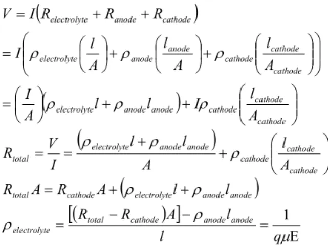
The effect of electrolyte concentration on the resistivity of the electrolyte has been studied. The output voltage was measured less than 0.2% rating output accuracy at 6 A constant current for 3 minutes during the micro arc oxidation. The ramp time to reach up to the set voltage was fixed at 1,000 ms. As shown in the equation below, the voltage drop across the cathode and the anode is equal to the product of the current and Rtotal = Relectrolyte + Ranode
+ Rcathode.
( )
( )
( )
( )
( )
[ ]
= Ε
−
= −
+ +
=
⎟⎟⎠
⎜⎜ ⎞
⎝ + ⎛
= +
=
⎟⎟⎠
⎜⎜ ⎞
⎝ + ⎛
⎟ +
⎠
⎜ ⎞
⎝
=⎛
⎟⎟
⎠
⎞
⎜⎜
⎝
⎛
⎟⎟⎠
⎜⎜ ⎞
⎝ + ⎛
⎟⎠
⎜ ⎞
⎝ + ⎛
⎟⎠
⎜ ⎞
⎝
= ⎛
+ +
=
μ ρ ρ
ρ ρ
ρ ρ ρ
ρ ρ
ρ
ρ ρ
ρ
q l
l A
R R
l l
A R A R
A l A
l l
I R V
A I l
l A l
I
A l A
l A
I l
R R R
I V
anode anode cathode
total e
electrolyt
anode anode e
electrolyt cathode
total
cathode cathode cathode anode
anode e
electrolyt total
cathode cathode cathode anode
anode e
electrolyt
cathode cathode cathode anode
anode e
electrolyt
cathode anode
e electrolyt
1
The same anode area sizes "A" (42 cm2) for all the samples have been applied in order to make the effect
EFFECTS OF ELECTROLYTE CONCENTRATION AND RELATIVE CATHODE ELECTRODE AREA SIZES IN TITANIA FILM FORMATION BY MICRO-ARC OXIDATION
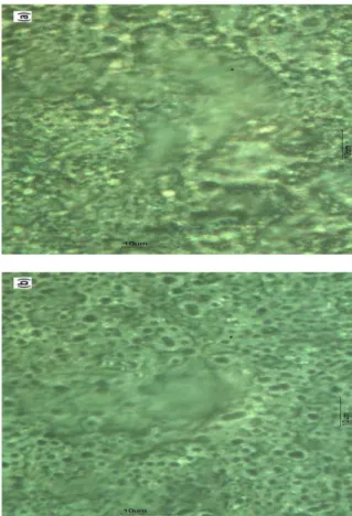
CORROSION SCIENCE AND TECHNOLOGY Vol.9, No.4, 2010 173 of anode area on Relectrolyte. Voltages between the anode and cathode with various electrolyte concentrations have been measured with the constant current 6 A. This in- dicated the surfaces of Ti plates were oxidized and the resistance of the surface was increased. The changes in the voltages differed from the experiments. When the changes in the voltages were small enough to be consid- ered a steady-state had been established the voltages were recorded and were referred to as stabilized voltages. In some domains discharges were still observed in visual after the voltages were stabilized. As shown in Fig. 2, the higher the concentration of the electrolyte, the lower the RtotalA value. Only variable to be affected by concentration change in the electrolyte in the equation above is ρelectrolyte. Thus, decrease in RtotalA can be explained by the decrease in ρelectrolyte correspondingly, which is due to the increase in the ion concentration in electrolyte as shown in the equation above. Thus, it will result in the more voltage drop across the oxide film to be built, which will promote the oxide film growth and the concentration of electrolyte has been linearly related with ρelectrolyte. Fig. 3(a) shows the oxide film produced by the lower concentration of the electrolyte is thinner and less uniform than the film by the higher concentration, which is thick and porous (Fig.
3(b)). The film thickness has been measured by the Alpha Step 500 Profiler, the step has been formed by dipping in the Titania etching solution. We attribute this to the fact that with the lower concentration of the electrolyte, the division of the source voltage applied across the oxide
Fig. 2. The change in the product of the total resistivity (Rtotal) and the anode electrode area with various electrolyte concentrations.
*The output voltage was measured less than 0.2% rating output accuracy at 6 A constant current for 3 minutes during the micro arc oxidation. The ramp time to reach up to the set voltage was fixed at 1,000 ms.
Fig. 3. Morphologies of the grown oxide films (a) 20g/L and (b) 30g/L electrolyte concentration.
Fig. 4. The change in the cathode resistance (Rcathode) with the anode electrode area (Acathode).
film was not high enough to continue the oxidation.
However, a further increase in the concentration of the electrolyte will make the ion mobility μ to be lower, which may make ρelectrolyte back to increase. It will result in the more voltage drop across the electrolyte, which causes the lesser voltage drop across the anode correspondingly.
The effect of the cathode area on Rcathode has been
YONG K. LEE AND KANGSOO LEE
174 CORROSION SCIENCE AND TECHNOLOGY Vol.9, No.4, 2010
studied. As increasing Acathode, Rcathode is getting smaller and then saturated as expected and it was shown in Fig.
4 and it draws a conclusion that the cathode area size must be bigger than the anode area size in order to mini- mize the voltage drop across the cathode. The ratio of the cathode area size to the anode area size must be bigger than 8 in order to minimize and eliminate the effects of the relative cathode area size. Otherwise, the cathode will be another source for voltage drop, which is detrimental to and slows down the oxide growth.
4. Conclusion
The roles of the electrolyte concentration and relative cathode electrode area sizes in the grown oxide film during titanium MAO (micro-arc oxidation) were investigated.
The higher the concentration of the electrolyte, the lower the RtotalA value. The oxide film produced by the lower concentration of the electrolyte is thinner and less uniform than the film by the higher concentration, which is thick and porous. As increasing Acathode, Rcathode is getting smaller and then saturated. The cathode area size must be bigger than the anode area size in order to minimize the voltage drop across the cathode. The ratio of the cathode area size to the anode area size must be bigger than 8. Otherwise, the cathode will be another source for voltage drop, which is detrimental to and slows down the oxide growth.
References
1. A. Aladjem, J. Mater. Sci., 8, 688 (1973).
2. J. Pouilleau, D. Devilliers, F. Garrido, S. Durand-Vidal, and E. Mahe, Mater. Sci. Eng. B, 47, 235 (1997).
3. P. Kurze, W. Krysmann, and H. G. Schneider, Cryst.
Res. Technol., 21, 1603 (1986).
4. S. D. Brown, G. P. Wirtz, and W. M. Kriven, Mater.
Sci. Monogr. High Perf. Ceram. Films Coat., 67, 221 (1991).
5. A. L. Yerokhin, X. Nie, A. Leyland, A. Matthews, and S. J. Dowey, Surf. Coat. Technol., 122, 73 (1999).
6. S. D. Brown, K. J. Kuna, and T. B. Van, J. Am. Ceram.
Soc., 54, 384 (1971).
7. T. Haneda, S. Ito, C. Yoshimura, and S. I. Ishida, Zairyo Gijutsu, 11, 274 (1993).
8. V. S. Rudnev, T. P. Yarovaya, D. L. Boguta, L. N.
Tyrina, P. M. Nedozorov, and P. S. Gordienko, J.
Electroanal. Chem., 497, 150 (2001).
9. X. Y. Liu, K. C. Paul, and C. X. Ding, Mater. Sci.
Eng. R, 47, 49 (2004).
10. Y. M. Wang, D. C. Jia, L. X. Guo, T. Q. Lei, and B. L. Jiang, Mater. Chem. Phys., 90, 128 (2005).
11. L. H. Li, Y. M. Kong, and H. W. Kim, Biomaterials, 25, 2867 (2004).
12. X. L. Zhu, K. H. Kim, and Y. S. Jeong, Biomaterials, 22, 2199 (2001).
13. X. L. Zhu, L. J. Ong, S. Y. Kim, and K. H. Kim, J.
Biomed. Mater. Res., 60, 333 (2002).
14. W. H. Song, Y. K. Jun, Y. Han, and S. H. Hong, Biomaterials, 25, 3341 (2004).
15. G. Sundarajan and L. R. Krishna, Surf. Coat. Technol., 167, 269 (2003).
16. W. Xue, Z. Deng, R. Chen, and T. Zhang, Thin Solid Films, 372, 114 (2000).
17. K. J. Park and J. H. Lee, Corros. Sci. Tech., 8, 227 (2009).