특별직교이방성 적층판이론에 의한 압연형교의 해석 Analysis of Rolled Beam Bridge by means of
Specially Orthotropic Laminates Theory
한봉구 Han, Bong-Koo * † · 이창수 Lee, Chang-Soo **
(Received August 2, 2010 ; Revised August 20, 2010 ; Accepted September 2, 2010)
ABSTRACT
The specially orthotropic plate theory is used for analysis of panels made of girders and cross-beams. The cross-sections of both girders and cross-beams are H-types. The results of application of this method to rolled beam bridge by using specially orthotropic plate theory is presented. The result is compared with that of the beam theory. Finite difference method is used for this purpose. The influence of the D 22 stiffness on the natural frequency is rigorously investigated. According to numerical examination given in this paper, the result by the plate theory is 2.43 times stiffer than that of beam theory.
요 지
본 연구에서는 거더와 가로보로 이루어진 패널을 특별직교이방성 판 이론을 응용하여 해석하였다. 거더와 가로보는 H 형단면을 사용하였다. 본 논문에서는 특별직교이방성 판 이론을 압연형교에 응용하였으며 해석한 결과를 제시하 였다. 해석결과는 보 이론과 비교하였다. 이러한 목적으로 본 논문에서는 유한차분법을 사용하였다. 고유진동수에 대한 D 22 강성의 영향을 철저히 검토하였다. 본 연구에서는 판 이론에 의해 수치해석을 해본 결과 보 이론보다 강 성이 2.43배가 되는 것을 알 수 있었다.
Key Words : Vibration analysis(진동해석), Specially orthotropic laminates theory(특별직교이방성적층판이론), Beam theory(보이론), Finite difference method(유한차분법)
*
정회원, 서울과학기술대학교 건설공학부 교수, 공학박사, 교신저자([email protected])**
정회원, 서울과학기술대학교 산업대학원 건축⋅
토목공학협동과정 (건기원), 석사과정1. INTRODUCTION
The problem of deteriorated highway slabs is very serious all over the world. Before m aking any decision on repair work, reliable evaluation is necessary. One of the non-destructive methods is to evaluate the in-situ stiffness of the slab by obtaining the natural frequencies of the system . By com paring the in-situ stiffness with the one obtained at the design stage, the degree of damage can be estim ated.
There are several m eans for slab system analysis such as (1) Beam strip method
(2) Composite beam theory between concrete slab and steel beams
(3) Gird analysis method for cross beams and girders The 3.1 Elevated Expressway in seoul, designed and built in 1967, used less than half of steel required by other best design at that tim e (Kim , 1968). The methods used were,
(1) Grid analysis (2) Composite action (3) Use of welding (4) Use of hybrid materials
(5) Use of high tension bolt and others.
Several existing design methods are studied and compared.
An extensive references are also given.
A m ethod of calculating the natural frequencies corresponding to the m odes of vibration of beams and tower structures with irregular cross sections and arbitrary boundary conditions was developed (Kim, 1995, Han et al., 2001, 2004, 2009, 2010).
In case of a bridge grid system with girders and
cross-beams, tables and methods by Leonhard (1950),
Hom berg (1956), M assonnet (1955), W atanabe (1966), Kim
(1968), and others can be used. Use of orthotropic plate theory in bridge design was reported by Chu and Krishnamoorthy (1963). Adotte (1967) reported second order theory in orthotropic plates. Hongladarom p et al.(1968) reported analysis of elasto-plastic grid system .
M any of the bridge and building floor system s, including the girders and cross- beams, and decks behave as the specially orthotripic plates which have [0°, 90°,0°]r fiber orientations.
2. METHOD OF ANALYSIS
The equilibrium equation for the specially orthotropic plate is :
D
1∂
4w
∂x
4+ 2 D
3∂
4w
∂ x
2∂ y
2+ D
2∂
4w
∂ y
4= q( x, y) (1)
where D1= D
11, D
2= D
22, D
3= D
12+ 2D
66
The assumptions needed for this equation are : (1) The transverse shear deformation is neglected.
(2) Specially orthotropic layers are arran- ged so that no coupling terms exist, i.e., . (3) No temperature or hygrothermal terms exist.
The purpose of this paper is to dem onstrate, to the practicing engineers, how to apply this equation to the slab systems made of plate girders and cross-beams.
In case of an orthotropic plate with boundary conditions other than Navier or Levy solution type, or with irregular cross section, or with nonuniform mass including point masses, analytical solution is very difficult to obtain.
Num erical methods for eigenvalue problems are also very much involved in seeking such a solution. Finite difference method (F.D.M ) is used in this paper. The resulting linear algebraic equations can be used for any cases with minor modifications at the boundaries, and so on.
The problem of deteriorating infrastructures is very serious all over the world. Before making any decision on repair work, reliable non-destructive evaluation is necessary. One of the dependable m ethods is to evaluate the in-situ stiffness of the structure by means of obtaining the natural frequency. By com paring the in-situ stiffness with the one obtained at the design stage, the degree of dam age can be estimated rather accurately.
The basic concept of the Rayleigh method, the m ost popular analytical method for vibration analysis of a single degree of freedom system , is the principle of conservation of
energy ; the energy in a free vibrating system must rem ain constant if no damping forces act to absorb it. In case of a beam , which has an infinite number of degree of freedom, it is necessary to assume a shape function in order to reduce the beam to a single degree of freedom system(Clough 1995).
The frequency of vibration can be found by equating the maxim um strain energy developed during the motion to the maxim um kinetic energy. This m ethod, however, yields the solution either equal to or larger than the real one. Recall that Rayleigh's quotient ≥1 (Kim , 1995). For a complex beam , assuming a correct shape function is not possible. In such cases, the solution obtained is larger than the real one.
Design engineers need to calculate the natural frequencies of such element but obtaining exact solution to such problem s is very m uch difficult. Pretlove reported a method of analysis of beam s with attached m asses using the concept of effective m ass. This m ethod, however, is useful only for certain sim ple types of beams. Such problem s can be easily solved by presented method.
A sim ple but exact m ethod of calculating the natural frequency corresponding to the first mode of vibration of beam and tower structures with irregular cross- sections and attached mass/masses was developed and reported by Kim in 1974. This method consists of deter- mining the deflected mode shape of the mem ber due to the inertia force under resonance condition. Beginning with initially “guessed” mode shape, “exact” mode shape is obtained by the process similar to iteration. Recently, this method was extended to two dimensional problems including composite lam inates, and has been applied to composite plates with various boundary conditions with/without shear deformation effects and reported at several international conferences including the Eighth Structures Congress (1990) and Fourth Materials Congress (1996) of Am erican Society of Civil Engineers.
This m ethod is used for vibration analysis in this paper.
A natural frequency of a structure is the frequency under which the deflected mode shape corresponding to this frequency begins to diverge under the resonance condition.
From the deflection caused by the free vibration, the force required to make this deflection can be found, and from this force, resulting deflection can be obtained. If the m ode shape as determined by the series of this process is sufficiently accurate, then the relative deflections (maxim um) of both the converged and the previous one should remain unchanged under the inertia force related with this natural frequency.
Vibration of a structure is a harmonic motion and the
amplitude may contain a part expressed by a trigonom etric
function. Considering only the first mode as a start, the
deflection shape of a structural member can be expressed as
w = W ( x, y ) F ( t) = W ( x, y ) s in ω t (2)
where
W : m aximum amplitude
ω : circular frequency of vibration t : time
By Newton's second law, the dynamic force of the vibrating m ass, m, is
F = m ∂ 2w
∂ t
2(3)
Substituting (2) into this,
F = - m (ω ) 2W sinω t (4)
In this expression, ω and W are unknowns. In order to obtain the natural circular frequency, ω , the following process is taken.
The magnitudes of the m aximum deflection at a certain number of points are arbitrarily given as
w(i,j)(1) = W (i,j)(1) (5)
where (i,j) denotes the point under consideration. This is absolutely arbitrary but educated guessing is good for accel erating convergence. The dynam ic force corresponding to this (maximum) amplitude is
F(i,j)(1)=m(i,j){ ω (i,j)(1)}2w(i,j)(1) (6)
The “new” deflection caused by this force is a function of F and can be expressed as
w(i,j)(2)=f{m (k,l){ ω (i,j)(1)}2 w(k,l)(1)}=
∑ k . l △ (i,j,k,l){m (k,l){ ω (i,j)(1)}2 w(k,l)(1)} (7)
where △ is the deflection influence surface. The relative (maximum) deflections at each point under consideration of a structural member under resonance condition, w(i,j)(1) and w(i,j)(2), have to rem ain unchanged and the following condition has to be held :
w(i,j)(1) / w(i,j)(2)=1. (8)
From this equation, w(i,j)(1) at each point of (i,j) can be obtained, but they are not equal in most cases. Since the natural frequency of a structural member has to be equal at all points of the mem ber, i.e., w(i,j) should be equal for all (i,j), this step is repeated until sufficient equal magnitude of w(i,j) is obtained at all (i,j) points.
However, in most cases, the difference between the maxim um and the minimum values of w(i,j) obtained by the first cycle of calculation is sufficiently negligible for engineering purposes. The accuracy can be improved by simply taking the average of the maximum and the m inim um, or by taking the value of w(i,j) where the deflection is the maxim um. For the second cycle, w(i,j)(2) in
w(i,j)(3) = f{m(i,j) [ ω (i,j)(2) ] 2 w(i,j)(2)} (9)
the absolute num erics of w(i,j)(2) can be used for convenience.
In case of a structural member with irregular section including com posite one, and non-uniformly distributed mass, regardless of the boundary conditions, it is convenient to consider the m ember as divided by finite number of elements.
The accuracy of the result is proportional to the accuracy of the deflection calculation.
For practical design purposes, it is desirable to simplify the vibration analysis procedure. One of the m ethods is to neglect the weight of the structural elem ent. The effect of neglecting the weight (thus mass) of the plate is studied as follow. If a weightless plate is acted upon by a concentrated load,
P= N⋅q⋅a⋅b , the critical circular frequency of this plate is
ω n = δ g
st (10)
where δ st is the static deflection.
Similar result can be obtained by the use of Eqs. (7) and (8).
[ ω (i,j) ]
2= 1
〔△ ( i, j, i, j) ⋅ P( i, j) g 〕 (11)
where,
P ( i, j) = N⋅q⋅a⋅b (12)
In case of the plate with more than one concentrated loads,
[ω (i,j) ]
2= 1
〔
∑k
.l △ (i, j, k, l) ․ P( k, l) g 〕 (13)
Fig. 1 Structure under consideration
Fig. 2 Cross-section If we consider the m ass of the plate as well as the
concentrated loads, w(i,j)(1) = w(i,j)(2)
= {∑k
.l △ (i,j,k,l)․m(k,l)․w(k,l)(1) + ∑m
.n △ (i,j,m,n)․ P( m , n ) g ․w(m,n)(1)}
m
.n △ (i,j,m,n)․ P( m , n ) g ․w(m,n)(1)}
×[ ω (i,j)(1) ] 2 (14)
where (m,n) is the location of the concentrated loads. The effect of neglecting the weight of the plate can be found by simply comparing Eqs. (13) and (14).
The method used in this paper requires the deflection influence surfaces. F. D. M . is applied to the governing equation of the specially orthotropic plates.
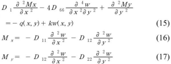
The num ber of the pivotal points required in the case of the order of error △2, where △ is the mesh size, is five for the central differences of the fourth order single derivative term s. This makes the procedure at the boundaries com plicated. In order to solve such problem, the three simultaneous partial differential equations of equilibrium with three dependent variables, w, M x, and M y, are used instead of Eq.(1) for the bending of the specially orthotropic plate.
D 1 ∂
2M x
∂ x
2- 4D
6 6∂
4w
∂ x
2∂ y
2+ ∂
2M y
∂ y
2 =- q( x, y) + kw( x, y) (15) M x = - D 1 1 ∂
2w
∂ x
2- D
1 2∂
2w
∂ y
2(16)
M y = - D 1 2 ∂
2w
∂ x
2- D
2 2∂
2w
∂ y
2(17)
If F. D. M . is applied to these equations, the resulting matrix equation is very large in sizes, but the tridiagonal matrix calculation schem e used by Kim is very efficient to solve such equations (Kim, 1967).
In order to confirm the accuracy of the F.D.M ., [A/B/A]r type laminate with aspect ratio of a/b=1m/1m =1 is considered.
For simplicity, it is assum ed that A=00, B=900, and r=1.
Since one of the few efficient analytical solutions of the specially orthotropic plate is Navier solution, and this is good for the case of the four edges simple supported, F.D.M . is used to solve this problem and the result is com pared with the Navier solution.
Calculation is carried out with different mesh sizes and the maxim um errors at the center of the plate are as follows.
10 x 10 case : 0.140 %
20 x 20 case : 0.035 % 40 x 40 case : 0.009 %
The error is less than 1%. This is smaller than the predicted theoretical errors ;
E s = 200,000 MPa,
- Girder - - Cross-beam -
H L = 500mm H T = 300 mm
B L = 200mm B T = 150mm
T
1L= 15 mm T
1T= 10 mm
T
2L= 20 mm T
2T= 18.5 mm
3. NUMERICAL EXAMINATION
The structure under consideration is as shown in Figs.1
and 2. The stiffnesses are given in Table 1. Type 1 is for the
specially orthotropic plate and Type 2 is the case of a sim ple
beam . In oder to a study the effect of the cross-beam sizes,
variable values of D 2 2 are given, in Table 2.
⋅Type 1 Type 2 D 11
D 22
101199927.65 21757837.94
101199927.65 0.00 Table 1. Stiffnesses
⋅Case 1 Case 2 Case 3 D 11
D 22
101199927.6 21757837.94
101199927.6 41618360.36
101199927.6 61478882.78 Table 2. Stiffnesses with variable D
2 2Type 1 2 Type2
Type1
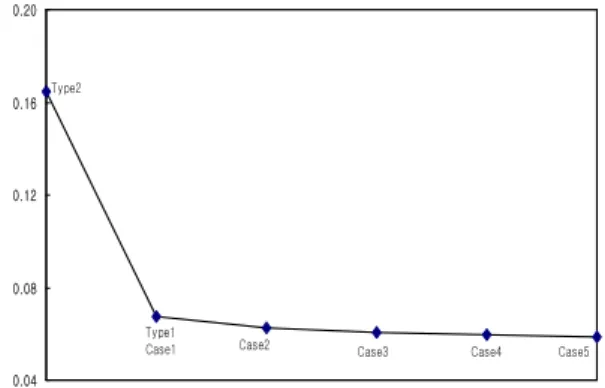
δ ( m ) 0.06765 0.16460 2.43
Table 3. Deflection at the center (m) Loading : 100 kN at the center
Case 1 2 3 4 5
δ ( m ) 0.06765 0.06262 0.06061 0.05951 0.05881 Case1/
Case i 1.0 1.0803 1.1162 1.1368 1.1503 Table 4. Deflection at the center (m)
Loading : 100 kN at the center
Type 1 2 Type2/
Type1
w(r ad/ sec ) 7.313 5.133 0.7019
Table 5. Natural Frequency (rad/sec).
Loading : 100 kN at the center
Case 1 2 3 4 5
w(r ad/ sec ) 7.313 7.471 7.539 7.577 7.603 Case I /
Case 1 1.0 1.0216 1.0309 1.0361 1.0397 Table 6. Natural Frequency (rad/sec)
Loading : 100 kN at the center
0.04 0.08 0.12 0.16 0.20
D e fl e c ti o n a t th e c e n te r (m )
Type1
Case1 Case2 Case3 Case4 Case5
Type2
Fig. 3 Deflection of each type and case.
5.00 6.00 7.00 8.00
N a tu ra l F re q u e n c y(r a d /s e c )
Type1 Case1
Case2
Case5 Case4 Case3
Type2