시간 선택 채널에서의 QO-STBC를 위한 피드백 결정 검출기
정회원 왕 우 상*, 종신회원 박 용 완**
Decision-Feedback Detector for Quasi-Orthogonal Space-Time Block Code over Time-Selective Channel
Youxiang Wang* Regular Member, Yongwan Park** Lifelong member 요 약
본 논문은 시간 선택적 페이딩 (time-selective fading) 채널에 강인한 준직교 시공간 블록 부호 (quasi-orthogonal space-time block code) 검출 기법을 제안한다. 제안된 검출 기법은 간섭 제거를 수행하고, 채널 이 심벌에서 심벌로 변할 때 안테나 간 간섭 또는 심벌 간 발생하는 간섭을 제거하기 위한 decision-feedback equalization 기능을 수행한다. Feed forward equalizer와 feedback equalizer를 얻기 위해 간섭제거를 수행한 후, 채널 Gram 행렬에 대해 Cholesky 분해를 사용한다. 실험 결과에 의해 제안된 검출 기법의 성능이 time-selectivity 환경에 적용하기 위해 기존에 제안되어온 검출 기법들에 비해 개선되었음을 보인다.
Key Words : Time-Selective Fading, QO-STBC, DFD, Interference Cancellation
ABSTRACT
This paper proposes a robust detection scheme for quasi-orthogonal space-time block code over time-selective fading channels. The proposed detector performs interference cancellation and decision feedback equalization to remove the inter-antenna interference and inter-symbol interference when the channel varies from symbol to symbol. Cholesky factorization is used on the channel Gram matrix after performing interference cancellation to obtain feed forward equalizer and feedback equalizer. It is shown by simulations that the proposed detection scheme outperforms the conventional detection schemes and the exiting detection schemes to time-selectivity.
※ This research was supported by the Yeungnam University research grants in 2009
* 영남대학교 정보통신공학과 ([email protected]), ** 영남대학교 전자정보공학부 ([email protected]) 논문번호:KICS2009-04-155, 접수일자:2009년 4월 15일, 최종논문접수일자 : 2009년 11월 22일
Ⅰ. Introduction
Orthogonal space-time block codes (OSTBC) from orthogonal designs have attracted considerable attention since Alamouti scheme was proposed [1]. OSTBC have two advantages, namely they have fast maximum-likelihood (ML) decoding, i.e., low complex symbol-wise decoding,
and they have full diversity. However when the number of the transmit antennas is more than two, full diversity and full rate cannot be simultaneously obtained because the orthogonal property cannot be achieved[2]. For increasing the symbol rates for complex symbols, OSTBC have been generalized to quasi-OSTBC (QO-STBC) in [3], [4], and [5] by relaxing the orthogonality
between all columns of a matrix. Although QO-STBC schemes offer a lower diversity order, they do lead to a full rate transmission
Most research on QO-STBC have been developed for flat fading channels. Different from [1], we consider here more realistic time-selective or fast fading but frequency-flat fading channels.
In wireless communications, time selectivity mainly caused by Doppler shifts and carrier frequency offsets, which jointly independent. It has been proved that the first-order Gauss-Markov random processes provides an accurate model for time-selective fading channels, and, therefore, this channel model will be adopted in this paper[6].
When the channels are time-selective, the interference is not completely eliminated by the linear combiner causing performance degradation
[1],[7]
. In [10], two-setp ZF (TS-ZF) detector was proposed for QO-STBC over time-selective fading channels. This method consist of two steps. A transform matrix is used at the first step to diagonalize the channel matrix at each receive antenna, then a simple least square detection is performed.
In this paper, decision-feedback detector (DFD) is considered with interference cancellation for QO-STBC under time-selective fading channel environment. We begin by establishing the channel and system model in section II. Related work and the proposed detection method are shown in section III. Section IV considers the simulation results, in this section some computer simulation results will be presented to confirm our scheme. Conclusions are given in section V.
The following notation will be adopted in this paper. Column vector and matrices are denoted by boldface letters; superscripts ∙, ∙∗, and ∙ denote transpose, complex conjugate, and complex conjugate transpose, respectively;
∙ stands for expectation; denotes the
× identity matrix, the subscript is omitted when the dimension of the matrix is obvious.
Ⅱ. Channel and System Model
2.1 Time-Selective Channel
We consider the communication scenario where the relative motion between the transmitter and receiver is significant. Therefore, the channel coherence time is comparable to the symbol duration. The channel is modeled as uncorrelated frequency-flat, time-selective Rayleigh fading. We adopt the first-order AR model for the time-varying channel gains [6]. The channel gains
which shows the channel coefficient from transmit antenna to the receive antenna are modeled as independently identically distributed (i.i.d.) circularly complex Gaussian random variables having zero-mean and variance .
The channel gains are assumed invariant within one signaling interval but vary from one signaling interval to another according to
… …, (1)
where is the number of transmit antennas,
is the number of receive antennas, the noise
is zero-mean complex Gaussian with variance
and is statistically independent of
, and the coefficient can be estimated as detailed in [6]. According to the Jake’s model [7], is zero-mean complex Gaussian process, and has time- autocorrelation properties governed by Doppler rate as in
∗
, (2)where ∙ is the zero-th order Bessel function of the first kind denotes the maximum Doppler shift and is symbol duration.
2.2 QO-STBC Scheme
Jafarkhani first proposed space-time block codes from quasi-orthogonal designs. For four transmit
antennas, a code with transmission rate one was extended for the concept of the Alamouti's scheme as follows:
∗ ∗
∗∗ ∗∗ ∗∗
∗∗
. (3)
The received signals can be given as
. (4)
Assuming a fading propagation environment and one receive antenna (we define the index of
as the number of transmit antenna to replace
, we can express the received signal vector
, channel matrix , transmitted signal vector and noise vector as
∗∗
∗∗
(5)
∗ ∗
∗ ∗
∗ ∗
∗ ∗
where the transmitted signal vector
includes four symbols , is the additive white Gaussian noise (AWGN) vector with variance
.
For such space-time code, the receiver can be decomposed in two steps: the space-time matched filtering operation, and the decoding part. By applying the matched filter in flat fading channel results in Gram matrix of the channel shown as
. (6)Under the flat fading, the channel will not change during one transmit block, so we can express the diagonal element as the sum of the 4 square magnitude of the channel coefficients :
∗ ∗
, (7)
where ∙ denotes the real part of the complex. In the case of time-selective fading channels, the Gram matrix can be given as
∗∗ ∗
∗
(8)The diagonal elements , , and
denote the diversity factor, and the anti-diagonal [8] elements , , and consist of irreducible inter-symbol interference (ISI) and inter-antenna interference (IAI) caused by non-orthogonal code matrix and time-selective channels, the off-diagonal elements (the part except the diagonal elements and the anti-diagonal elements of the Gram matrix) , … and their conjugate transpose are time-selective errors caused by time-selective channels. In (6) the anti-diagonal elements of Gram matrix have almost the same absolute value, it is irreducible as the code matrix is not orthogonal under the slow fading channels. Under the time-selective fading, the elements and
∗ are not equal to zero as the channel matrix is not orthogonal.
They were also generalized as interference between four transmit antennas [10]. When the channel varies quickly from symbol to symbol, and
∗ become significant and the transmit
antennas severely interfere with each other.
Ⅲ. DFD for QO-STBC over Time- Selective Fading Channels
3.1 Related Work
Linear receivers (ZF and MMSE detectors) have the lower decoding complexity, but ZF detector suffers from noise enhancement and MMSE suffers from the residual interference from other antennas. They can be described by [11]:
, (9)
where for the ZF detector and
for the MMSE detector.
In [3] the author proposed one low complexity ML (LC-ML) method which obtained the same performance as ML but half complexity burden.
The original ML method can be shown as
∈
∥ ∥, (10)
where is the transmission constellation. By substituting ′ for , (10) can be rewritten as:
⊆
∥′ ∥. (11)
LC-ML method separates the ML decision metric into the sum of two independent terms
[3]. Thus, the minimization for ML decoding can be done separately on these two terms.In [10], two-setp ZF (TS-ZF) detector was proposed for QO-STBC over time-selective fading channels. This method consist of two steps. A transform matrix is used at the first step to diagonalize the channel matrix at each receive antenna,
′, (12)
where
and 's are he diagonal elements of . And then a simple least square detection is performed,
∈
, (13)where …, and is the row of .
3.2 Proposed DFD Method
Under the environment of time-selective channels, the decoding method in [3] cannot be employed as the ML decision metric can no longer be calculated as the sum of two orthogonal terms. For linear detectors, ZF and MMSE both suffer from performance degradation when the channel varies quickly from symbol to symbol.
Therefore, in this section nonlinear equalizers are proposed to provide better perform- ance by subtracting the interference resulting from time-selective channels and feeding back past decisions on already detected symbols.
In the proposed DFD detector, linear detectors are used to get the soft estimates of transmitted signals. By using these estimates, the interference on the off-diagonal elements of the channel Gram matrix caused by the time-selective fading channels. At the last step, Cholesky factorization is used for decision-feedback to eliminate the interference on the anti-diagonal elements of the channel Gram matrix.
The proposed DFD detector consists of two parts, in the first part of which interference due to off-diagonal elements of the channel Gram matrix is canceled.
1) In order to eliminate the IAI interference, soft estimates should be obtained which are given by using linear detectors as:
, (14)where ∈× denotes the estimates at the output of the linear detector (ZF or MMSE). Note that in this paper, we consider transmit antennas, receive antennas and an interval of
available in one transmission block, then
is the × receive signal vector, and
is the × channel matrix. In order to easily explain the detection process, we only consider one receive antenna in this section. So now has dimensions × and is the
× matrix.
Based on the linear detectors' solution, interference cancellation can be performed subsequently:
′ , (15)
where ′ represents the estimates at the output of the space-time match filter. As
, the matrix comprises the residual elements of by subtracting the diagonal and anti-diagonal elements,
. We consider most signal information on the diagonal and anti-diagonal elements in , while the off-diagonal elements can be regarded as inter-antenna interference (IAI) which should be cancelled.
2) The anti-diagonal parts of the channel Gram matrix, , caused by the time-selective fading channels and the nor-orthogonal code matrix, which are canceled by using decision-feedback equalizer (DFE) according to the Cholesky decomposition. It can be given as
, (16)
where ∈× is an upper triangular matrix with diagonal having the value one,
∈× is a diagonal matrix. DFE can
be constructed by premultiplying the matrix
, simply denoted as
, (17)
where ∈× is the output of DFE.
As is upper triangular, the decision on a signal recursively in reverse order of the components of signal vector by using past decisions on previous signals. Decision are made recursively as
≐,
, (18)in which … , denotes the
entry of and ∙ denotes a quantization operation performed with a threshold detector. There are only diagonal and anti-diagonal elements in , which has the same format as the channel Gram matrix of the QO-STBC over slow or quasi-static fading channels shown in (8). So the interference is only in two symbol pairs
and
. In DFE procedure, the feedback filter shown as
, (19)where and are the coefficients of the feedback filter. The filter detects and
separately, then uses this information to help make a decision about and , respectively.
DFE essentially performs successive interference cancellation, i.e. a symbol is first estimated based on a linear equalizer, and the estimated symbol is then cancelled off from the other received symbols through a feedback filter [12]. This
Parameters Setting Antenna configuration 4 Tx, 1 Rx Fading channel Rayliegh fading Doppler model Jake's model Carrier frequency
Symbol duration × Modulation level QPSK Table 1. Simulation parameters
0 5 10 15 20 25 30
10-5 10-4 10-3 10-2 10-1 100
SNR (dB)
BER
LC-ML TS-ZF ZF MMSE ZI-DFD MI-DFD
Fig. 1 The BER performance of the proposed detector, compared to the decoder in [3] and [10] under perfect CSI, Tx = 4, Rx = 1,
process is iterated until all transmitted symbols are adequately estimated. DFE is a non-linear equalization approach due to its feedback cancellation mechanism. As the interference cancellation and feedback cancellation mechanism, we can obtain a performance improvement compared to the linear block equalizer.
Ⅳ. Simulation Results
In this section, simulation results are presented for the proposed schemes. We consider a QO- STBC system with four transmit antennas and one receive antennas, the channel is variant between any two continuous intervals, and Jake’s model is used for Rayleigh fading channel simulations. We assume that the channel state information (CSI) can be accurately estimated at the receive side.
Fig. 1 shows BER simulation results of the proposed detectors and the detectors proposed in [3] and [10], respectively, which are referred as the LC-ML and TS-ZF in the figure. All the simulations are under the condition that the speed is 300 km/h (corresponding to ).
From Fig. 1, we know that the LC-ML detector described in [3] suffers from an irreducible error floor due to the effect of the time-selective fading channels. It can be seen that the TS-ZF detector in [10] achieves the same performance as the general ZF detector because both methods completely remove the intertransmit- antenna interference and induce the same conditional covariance noise with zero-mean. The MMSE detector is superior to the ZF detector by taking into account the noise correlations existing in the decision variables. It has almost the same
performance as the proposed ZI-DFD detector (ZF detector is used in first step).
In Fig. 1, the performance of the proposed detectors with ZI-DFD and MI-DFD outperform the performance of their corresponding linear detectors, as interference cancellation is used in two schemes which can improve the system performance by canceling the interference caused by time-selective channels and DFE can suppress ISI and mitigate the effect of error propagation.
The MI-DFD performs best, followed by the MMSE, the ZI-DFD, the ZF.
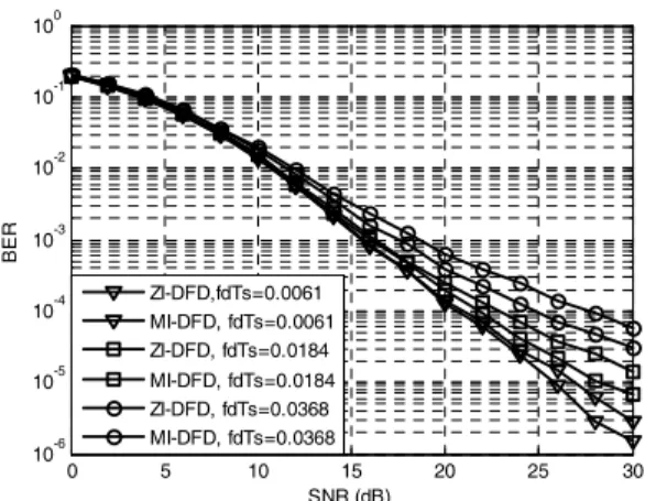
Fig. 2 shows the BER results of the ZI-DFD and MI-DFD respectively at different vehicle speeds: 50, 150, 300km/h. The figure demonstrates that MI-DFD is able to effectively suppress ISI and recover the transmitted symbols.
As the noise correlations have been considered in the decision variables with MMSE criteria comparing to ZF criteria shown in (14).
For the proposed detectors, the first step results will dominate the total system performance. It should be obtained as accurate as possible, so the MMSE criteria perform better than ZF criteria. It also can be seen that the MI-DFD detector significantly outperforms the ZI-DFD detector when the channel varies rapidly.
Next we want to investigate the effects of the channel estimation errors on the performance of
0 5 10 15 20 10-4
10-3 10-2 10-1 100
SNR (dB) BER ZF, Mismatched channel
ZF, Perfect channel MMSE, Mismatched channel MMSE, Perfect channel ZI-DFD, Mismatched channel ZI-DFD, Perfect channel MI-DFD, Mismatched channel MI-DFD, Perfect channel
Fig. 3. The performance comparison of the proposed detectors and the existing detectors under mismatched CSI, Tx = 4, Rx = 1,
0 5 10 15 20 25 30
10-6 10-5 10-4 10-3 10-2 10-1 100
SNR (dB)
BER
ZI-DFD,fdTs=0.0061 MI-DFD, fdTs=0.0061 ZI-DFD, fdTs=0.0184 MI-DFD, fdTs=0.0184 ZI-DFD, fdTs=0.0368 MI-DFD, fdTs=0.0368
Fig. 2. The performance of the ZI-DFD and MI-DFD, Tx
= 4, Rx = 1.
the proposed detectors and the conventional linear detectors. The channel is modeled as
, (20)
… …
where is the perfect channel gain and
is the channel estimation error, which is modeled as i.i.d. circularly complex Gaussian random variable having zero mean and variance
and are statistically independent of .
is the mismatched channel gain and is also i.i.d. zero mean circularly complex Gaussian random variable with variance
. Fig.
3 shows BER results of the proposed detectors and the existing detectors with for
.
It is observed that all the detectors experience significant performance losses in the presence of channel mismatches. Dashed ellipse is used to show the performance degradation between the perfect channel and the mismatched channel. The major axis denotes the gap. For the same difference which is shown by the same length of the axis, the ellipses locate at different SNR points. From the figure, it is evident that the gaps between the performance under perfect CSI and performance under mismatch channel for the
proposed detectors are smaller than the corresponding gaps for the existing detectors. For the same gap, the MI-DFD has the largest SNR value, and the MMSE has the larger SNR value than the ZI-DFD and ZF.
Ⅴ. Conclusions
In this paper, decision-feedback detectors for QO-STBC over time-selective fading channels have been proposed. The proposed schemes have better performance than their corresponding linear detectors and the existing detectors in [3], [10].
From simulation results, we assessed their performance over time-selective fading channels are characterized by the Doppler shift. The MI-DFD detector significantly outperforms the ZI-DFD detector when the channel varies rapidly.
Both detectors can achieve better performance by mitigating the impact of time-selective fading channels with interference cancellation, while the computational complexity is a litter higher than that of the existing detectors.
References
[1] S. M. Alamouti, “A simple transmit diversity technique for wireless communications,” IEEE J. Select. Areas Commun., Vol.16, pp.1451-
1458, Oct. 1998.
[2] V. Tarokh, H. Jafarkhani, and A. R.
Calderbank, “Space-time block codes from orthogonal designs,” IEEE Trans. Inform.
Theory, Vol.45, pp.1456–1467, July 1999.
[3] H. Jafarkhani, “A Quasi-Orthogonal Space- Time Block Code,” IEEE Trans. Commun, Vol.49, pp.1-4, Jan.2001.
[4] N. Sharma and C. B. Papadias, “Improved Quasi-Orthogonal Codes Through Constellation Rotation,” IEEE Trans. Commu., Vol.51, pp.332-335, March 2003.
[5] O. Tirkkonen, A. Boariu and A. Hottinen,
“Minimal non-orthogonality rate 1 space-time block code for 3+Tx,” IEEE Int. Symposium on Spread Spectrum Techniques & Applications, New Jersey, USA, pp.429-432, Sep. 2000.
[6] H. S. Wang and P.-C. Chang, “On Verifying the First-Order Markovian Assumption for a Rayleigh Fading Channel Model”, IEEE Trans.
Veh. Technol., Vol.45, No.2, pp.353-357, May 1996.
[7] Z. Liu, X. Ma, and G.B. Giannakis, “Space-time coding and Kalman filtering for time-selective fading cahnnels.” IEEE Trans. Commu., Vol.50, No. 2, pp.183-6, Feb. 2002.
[8] F.-C. Zheng and A. G. B Burr, “Receiver Design Orthogonal Space-Time Block Coding for four transmit antenna over Time-Selective Fadin Channels,” Proc. IEEE Globecom 2003.
San Francisco. USA.
[9] Roger A. Horn and Charles R. Johnson, Matrix Analysis, Cambridge University Press, 1985.
[10] F.-C. Zheng and A.G.Burr, “Signal Detection for Non-Orthogoanl Space-Time Block Over Time-Selective Fading Channels,” IEEE Communications Letters. Vol.8, No.8, pp.491-493. Aug 2004.
[11] S. Nahm.and, W. Sung, “Time-Domian Equalization for the Orthogonal Multi- Carrier CDMA System” in Proc. GLOBECOM ’96, Vol.3, pp.1583-1587, Nov. 1996.
[12] L. Li, Y. Yao and H. Li, “Transmit Diversity and Linear and Decision-Feedback Equali- zations for Frequency-Selective Fading
Channels” IEEE Trans. Veh. Tech. Vol.52, No.5, pp.1217-1231, Sep. 2003.
왕 우 상(Youxiang Wang) 정회원
2006년 2월 영남대학교 정보통 신공학과 석사
2006년 3월~현재 영남대학교 정보통신공학과 박사과정
<관심분야> MIMO, 시공간 부 호, Multiuser-MIMO
박 용 완(Yongwan Park) 종신회원
1982년 2월 경북대학교 전자공 학과 학사
1984년 2월 경북대학교 전자공 학과 석사과정
1989년 2월 SUNY at Buffalo, 전자공학과 석사
1992년 2월 SUNY at Buffalo, 전자공학과 박사
1992년~1993년 캘리포니아공과대학 Research Fellow 1994년~1996년 SK Telecom 기술연구부장 1996년~현재 영남대학교 정보통신공학과 교수 2000년~2000년 NTT DoCoMo 연구소 초빙교수 2003년~2004년 UC Irvine 방문교수
2004년~현재 영남대학교 지역기술혁신 센터장 2006년~현재 (사)대한임베디드 공학회 총무이사 2008년~현재 IEEE VTS 한국위원장
<관심분야> 이동통신, 차세대통신시스템, 위치측위 기술
![Fig. 1 The BER performance of the proposed detector, compared to the decoder in [3] and [10] under perfect CSI, Tx = 4, Rx = 1, ](https://thumb-ap.123doks.com/thumbv2/123dokinfo/5289551.374220/6.799.423.713.93.327/fig-ber-performance-proposed-detector-compared-decoder-perfect.webp)