• 검색 결과가 없습니다.

열플라즈마에 의한 복합 나노 입자 제조

N/A
N/A
Protected

Academic year: 2021

Share "열플라즈마에 의한 복합 나노 입자 제조"

Copied!
4
0
0

로드 중.... (전체 텍스트 보기)

전체 글

(1)

Appl. Chem. Eng., Vol. 21, No. 6, December 2010, 676-679

676

열플라즈마에 의한 복합 나노 입자 제조

정민희⋅김헌창

호서대학교 화학공학과

(2010년 10월 22일 접수, 2010년 10월 27일 채택)

-

Thermal Plasma Synthesis of Nano Composite Particles

Min Hee Jeong and Heon Chang Kim

Department of Chemical Engineering, Hoseo University, Asan 336-795, Korea (Received October 22, 2010; Accepted October 27, 2010)

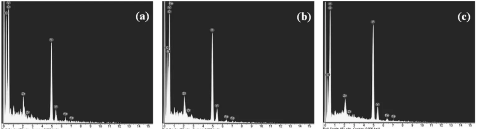
이송식 직류 열플라즈마를 이용하여 ZrVFe 합금모재로부터 복합 나노 입자를 제조하여 플라즈마 가스 유량이 제조된 입자의 특성에 미치는 영향을 분석하였다. 입자의 특성은 전계방출 주사전자 현미경(FE-SEM), 입도 분석기(PSA), X선 분광기(EDS), X선 회절계(XRD), Brunauer-Emmett-Teller (BET) 비표면적 측정기를 사용하여 분석하였다. 플라즈마 가 스 유량을 20 L/min에서 40 L/min으로 증가시키면 평균입자크기가 91 nm에서 55 nm로 감소하며 입도분포의 기하학적

편차가 줄어들었고 비표면적은 200 m 2 /g에서 255 m 2 /g으로 증가하였으며 제조된 입자의 조성에는 큰 영향을 미치지

못했지만 결정성이 향상되었다.

Nano composite particles were synthesized from a bulk ZrVFe alloy ingot by transferred DC thermal plasma. Effects of plas- ma gas flow rate on the characteristics of the produced nano composite particles were investigated. The characteristics of the synthesized powder were analyzed by field scanning electron microscopy (FE-SEM), light scattering particle size analyzer (PSA), energy dispersive X-ray spectroscopy (EDS), X-ray diffractometer (XRD), and Brunauer-Emmett-Teller (BET) surface area analyzer. As the flow rate of plasma gas increased from 20 L/min to 40 L/min, the average particle size decreased from 91 nm to 55 nm, the particle size distribution became narrower, the surface area increased from 200 m 2 /g to 255 m 2 /g, the particle composition was nearly unaffected, and the particle crystallinity was improved.

Keywords: thermal plasma, nano composite particle, particle size distribution, quenching rate

1. Introduction

1)

Plasma Display Panel (PDP) is considered as the most promising candidate for large area display among various Flat Panel Displays (FPD’s) due to its manufacturing process appropriate for a large dis- playing area, high speed addressing ability and good display quality [1]. The large plasma display panel is divided into tiny cells by barrier ribs, and the electric discharge gas filled in the cell is one of important factors determining the display quality and life time of the PDP. By the nature of plasma, heavy ions in the cell continuously bombard sur- rounding walls during operation, resulting in the emission of undesired species from the wall, in turns contaminating the plasma gas, and con- sequently degrading the display quality. To extend the PDP’s life time with good display quality, it is necessary to continuously eliminate contaminants emitted from protective layer, barrier rib and fluorescent substances[2,3]. Installation of getter materials, such as Zr-V-Fe alloy powder, in the PDP cell is a potential solution to overcome such problems.

† 교신저자 (e-mail: [email protected])

In fact, Zr-V-Fe getter materials are currently utilized in various appli- cations[4,5] and commercially available (for an example, ST707 from SAES Getters, Inc.). However the particle size of the commercial get- ters is in the range of micrometers, limiting their applicability to the PDP cell. Hence it is imperative to produce the Zr-V-Fe getter material with the particle size in the range of nanometers.

Nano particles can be produced by various methods, such as sol-gel[6],

spray pyrolysis[7], infrared heating[8] freeze-drying[9], laser ablation

[10], wire explosion[11], and thermal plasma[12]. While most methods,

requiring pre- and post-treatment, are time consuming and expensive,

thermal plasma is simple and fast, thus cost effective technique to pro-

duce nano particles, specially for materials with extremely high evapo-

ration temperature such as Zr. In this work, nano composite particles

were prepared from a bulk ZrVFe alloy ingot by transferred DC ther-

mal plasma. Effects of plasma gas flow rate on the characteristics of

the produced nano composite particles, such as particle size distribution,

mean particle size, surface area, particle composition and crystallinity,

were investigated.

(2)

열플라즈마에 의한 복합 나노 입자 제조 677

Appl. Chem. Eng., Vol. 21, No. 6, 2010 Figure 1. Schematic of thermal plasma system for synthesis of nano

particles.

Figure 2. SEM images and particle size distributions for particles synthesized with plasma flow rates of (a) 20 L/min, (b) 30 L/min, and (c) 40 L/min.

Figure 3. Effects of plasma gas flow rate on mean particle diameter and BET surface area.

2. Experiment

Figure 1 shows a schematic diagram of the thermal plasma system employed to synthesize ZrVFe alloy nano particles. The system con- sists of five sections : a DC plasma torch generating plasma flame from arc, a reaction chamber providing extremely high temperature environ- ment for the formation of nuclei and clusters as well as for the growth of nano particles, a quenching tube in which the synthesized nano par- ticles are quickly cooled down to prevent further growth, a collection chamber where the particles are deposited on a filter, and a scrubber eliminating pollutants from the effluent.

The constituent elements considered for the generation of nano com- posite particles were zirconium (Zr), vanadium (V) and iron (Fe). They were melted together by arc in a vacuum chamber, forming a bulk ZrVFe alloy ingot to be used as a raw material. The molar ratio of the con- stituent elements in the raw material was 57 : 35.8 : 7.2 so as to mim- ic the composition of commercially available getter ST707.

The plasma torch was operated in a transferred mode so that the arc extended from the electrode of the plasma torch to a raw material, ZrVFe alloy ingot. The ingot was placed 3 cm below the plasma noz- zle, the input current to generate thermal plasma was fixed at 150 A while the flow rate of the plasma gas, pure argon, was varied from 20 L/min to 40 L/min. The characteristics of the particles produced for 20 min were analyzed by FE-SEM (FEI, Quenta 200), EDS (Horiba), XRD (Rigaku, MAX-2500V), PSA (Malvern, Masrersizers & Zetasizers) and BET analyzer (Micrometrics, ASAP2020).

3. Results and Discussion

Figure 2 shows the SEM images and size distributions of the par- ticles synthesized by the transferred thermal plasma with the various flow rate of the plasma gas. From the SEM images, the particles were found to be spherical although severely agglomerated, and the particle size was found to decrease as the flow rate increased. Although the shape of the particle size distribution obtained from the PSA was al- most unaffected as the flow rate increased from 20 L/min to 40 L/min, the portion of smaller particles near 50 nm was found to noticeably increase. In the transferred thermal plasma system, the raw material

first becomes liquefied by arc and then evaporated in thermal plasma

environment, super saturation in vapor phase generates abundant nuclei

subsequently forming clusters which grow to particles by condensation

and coalescence. As the plasma gas flow rate increase, the current den-

sity of the arc more confine in the center, increasing the maximum

temperature of the plasma flame. Since the plasma flame radially shrinks,

(3)

678 정민희⋅김헌창

공업화학, 제 21 권 제 6 호, 2010

Figure 4. EDS analyses of particles synthesized with plasma flow rates of (a) 20 L/min, (b) 30 L/min, and (c) 40 L/min.

Figure 5. Effects of plasma gas flow rate on XRD patterns of particles.

however, the particles flow out of the plasma flame more quickly and have less chance to further grow by condensation and coalescence. In addition, the higher quenching rate resulting from the stiffer temper- ature gradient also plays a role in the abundant production of smaller particles. Consequently, as the plasma gas flow rate increased from 20 L/min to 40 L/min, the average particle size decreased from 91 nm to 55 nm, as shown in Figure 3, and the surface area measured by BET correspondingly increased from 200 m 2 /g to 255 m 2 /g.

Figure 4 shows EDS analyses of particles produced as the plasma gas flow rate varied. In all cases, the compositions of the particles were found to significantly differ from that of the raw material. The least constituent element of the particles was Fe, as expected, since Fe was also the least in the raw material. Although the raw material was prepared to have the highest Zr content, V was the highest constituent element of the particles since the boiling point of Zr is much higher than those of V and Fe. Nonetheless the V content of the particles somewhat increased as the plasma gas flow rate increased. Furthermore the oxygen peak was also observed implying the formation of oxides.

Figure 5 compares XRD patterns of the particles synthesized with vari- ous flow rates of the plasma gas. In all cases, oxide particles were formed, as expected from the EDS analyses. Although the particles may be oxidized in part during sampling, it is more believed that the reaction chamber was not perfectly sealed from surroundings. To pre- vent the severe oxidation of the particles, several attempts are being

made, such as carving grooves around the flanges where the plasma torch is attached to the reaction chamber, installing o-rings in the grooves, operating the reaction chamber at the pressure a little higher than atmosphere, and intentionally forming a thin oxide layer on the particle surface before sampling. Nonetheless each peak was observed to became sharper and the intensity increased as the the plasma gas flow rate increased, indicating that the crystallinity improved.

4. Conclusions

A transferred DC plasma was utilized to synthesize spherical nano composite particles from a ZrVFe ingot. Although the size of the pro- duced particles was, in overall, in the range between 30 nm and 200 nm, the small particles near 50 nm became more abundant as the plas- ma gas flow rate increased due to the shorter residence time of the par- ticles in the plasma flame region and to the higher quenching rate.

Consequently, the average particle diameter monotonically decreased from 91 nm to 55 nm, and the surface area increased from 200 m 2 /g to 255 m 2 /g as the plasma gas flow rate increased from 20 L/min to 40 L/min. Furthermore the particle size distribution became narrower implying that the particle size became more uniform, and the crystal- linity also improved. The results imply that the particle properties can be controlled by the plasma gas flow rate.

References

1. W. B. Choi, B. K. Ju, Y. H. Lee, S. J. Jeong, N. Y. Lee, M. Y.

Sung, and M. H. Oh, J. Electrochem. Soc., 146, 400 (1999).

2. G. Chakhovskoi, C. E. Hunt, and M. E. Malinowski, Displays, 19, 179 (1999).

3. R. Chalamala, D. Uebelhoer, and K. A. Dean, J. Vac. Sci. Technol.

A, 18, 343 (2000).

4. D. Petti, M. Cantoni, M. Leone, R. Bertacco, and E. Rizzi, Appl.

Surf. Sci., 256, 6291 (2010).

5. P. Roupcová and O. Schneeweiss, J. Alloys Compd., 492, 160, (2010).

6. W. Liu, D. Wu, and J. Yang, Int. J. Mater. Prod. Tech., 37, 297 (2010).

7. H. Y. Koo, J. H. Yi, and Y. C. Kang, J. Alloys Compd., 489, 456

(2010).

(4)

열플라즈마에 의한 복합 나노 입자 제조 679

Appl. Chem. Eng., Vol. 21, No. 6, 2010 8. S. Oh and S. Lee, J. Nanosci. Nanotechnol., 10, 366 (2010).

9. X. Xi, X. Xu, Z. Nie, S. He, W. Wang, J. Yi, and Z. Tieyong, Int. J. Refract. Met. Hard Mater., 28, 301 (2010).

10. C. A. Crouse, E. Shin, P. T. Murray, and J. E. Spowart, Mater.

Lett., 64, 271 (2010).

11. L. H. Bac, Y. S. Kwon, J. S. Kim, Y. I. Lee, D. W. Lee, and J.

C. Kim, Mater. Res. Bull., 45, 352 (2010).

12. A. J. Song, M. Z. Ma, W. G. Zhang, H. T. Zong, S. X. Liang,

Q. H. Hao, R. Z. Zhou, Q. Jing, and R. P. Liu, Mater. Lett., 64,

1229 (2010).

수치

Figure 2. SEM images and particle size distributions for particles  synthesized with plasma flow rates of (a) 20 L/min, (b) 30 L/min, and  (c) 40 L/min.
Figure 4. EDS analyses of particles synthesized with plasma flow rates of (a) 20 L/min, (b) 30 L/min, and (c) 40 L/min.

참조

관련 문서

Scanning electron microscopy/energy dispersive X-ray spectroscopy (SEM/EDX) analysis was used to investigate the surface conditions and exposed platinum

합성된 촉매의 조성과 구조를 분석하 기 위해 SEM (Scanning Electron Microscopy)-EDS (Energy Dispersive Spectroscopy) 분석과 TEM (Transmission Electron Microscopy)

합성된 분말은 X-ray diffraction (XRD), field emission scanning electron microscopy (FE-SEM), energy-dispersive X-ray spectroscopy (EDS), thermogravimetry (TG) 를

Ion plated surface of each specimen was observed with field emission scanning electron microscopy (FE-SEM), energy dispersive X- ray spectroscopy

The morphology, element distribution, crystal structure, roughness and energy of the surface were investigated by scanning electron microscopy (SEM), energy-dispersive

The synthesized PdNPs were characterized by UV-vis spectroscopy, transmission electron microscopy (TEM), scanning electron microscopy (SEM), X-ray diffraction (XRD),

Through x-ray diffraction (XRD), scanning electron microscope (SEM), energy dispersive spectroscopy (EDS), and atomic force microscopy (AFM), it is found that

CIGS thin films have been characterized by X-ray diffraction(XRD), scanning electron microscopy(SEM), energy-dispersive spectroscopy(EDS), four-point probe