http://dx.doi.org/10.7839/ksfc.2016.13.3.008
제어밸브의 유량특성에 따른 에어스프링의 성능 변화
Effect of Control Valve Flow Rates Characteristics on the Performance of an Air Spring
한승훈
1․장지성
2*․지상원
2Seung Hun Han, Ji Seong Jang and Sang Won Ji
Received: 15 Jun. 2016, Accepted: 07 Jul. 2016
Key Words:Air Spring(에어스프링), Critical Pressure Ratio(임계압력비), Flow Rates Characteristics(유량특성), Impedance Characteristics(임피던스 특성), Transmissibility(진동전달율)
Abstract: This study describes the effect of the critical pressure ratio of a control valve on the performance of an air spring system composed of an air spring, auxiliary chamber, control valve and mass in order to suggest a more efficient design for an air spring system. The critical pressure ratio of the control valve is assumed to have a fixed value, but the critical pressure ratio of the control valve is known to have various values between 0.05 and 0.6, and the effect of the variation of the critical pressure ratio on the performance of the air spring system has not yet been reported. The analysis derives nonlinear and linear governing equations of the air spring system, including the critical pressure ratio of the control valve. This simulation study is presented to show that the impedance and transmissibility characteristics of the air spring system change due to variations in the critical pressure ratio of the control valve as well as its sonic conductance. As a result, the critical pressure ratio of the control valve should be maintained as large as possible to improve the vibration isolation characteristics of the air spring system.
* Corresponding author: [email protected]
1 Department of Control & Mechanical Engineering, Graduate School, Pukyong National University, Busan 48547, Korea 2 Department of Mechanical System Engineering, Pukyong National University, Busan 48547, Korea
Copyright Ⓒ 2016, KSFC
This is an Open-Access article distributed under the terms of the Creative Commons Attribution Non-Commercial License(http://
creativecommons.org/licenses/by-nc/3.0) which permits unrestricted non-commercial use, distribution, and reproduction in any medium, provided the original work is properly cited.
1. 서 론
에어스프링과 제어밸브, 배관 및 보조용기로 구성 된 에어스프링 시스템은 압력 변화 등에 의하여 스 프링 상수의 변경이 용이하며 충격 및 진동 절연 성 능이 우수하므로 다양한 분야에 사용되고 있다
1~2). 이러한 에어스프링 시스템의 성능 분석과 관련해서 는 배관 및 오리피스 단면적이 에어스프링의 성능에 미치는 영향에 대한 연구
3), 가진 주파수와 열전달효
과가 에어스프링의 히스테리시스 특성에 미치는 영
향에 대한 분석
4), 에어스프링의 유효단면적 변화가
스프링-부하 구동계의 주파수 응답에 미치는 영향을
분석한 연구
5), 초기압력이 에어스프링의 스프링 상수
에 미치는 영향을 분석한 연구
6), 열전달효과가 에어
스프링의 성능에 미치는 영향을 분석한 연구
7)등 다
양한 요소에 대한 연구가 진행되어 왔다. 이러한 요
소 중 제어밸브는 임계압력비를 이상적인 오리피스
로 가정하여 분석에 적용하여 왔지만
1~8), 실제로는
임계압력비가 광범위하게 변한다는 사실이 알려져
있다
9). 그러나, 이러한 변화가 에어스프링 시스템의
특성에 미치는 영향을 분석한 연구는 아직 보고되지
않고 있다. 본 연구에서는 제어밸브의 임계압력비 변
화가 에어스프링 시스템의 강성과 임피던스 및 에어
스프링-부하 구동계의 진동전달율에 미치는 효과를
고찰함으로써 에어스프링 시스템을 보다 효율적으로
설계할 수 있는 방안을 제시하고자 한다.
2. 에어스프링 모델
2.1 비선형모델
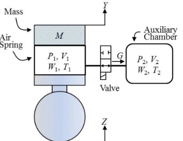
Fig. 1은 에어스프링과 제어밸브, 배관 및 보조용 기로 구성된 에어스프링 시스템을 나타낸다. Fig. 1에 서 G[kg/s]는 공기의 질량유량, M[kg]은 에어스프링 상부의 부하 질량, P[Pa]는 압력, T[K]는 온도, V[m
3] 는 체적, W[kg]는 공기질량, Y[m]는 에어스프링 상부 부하의 변위, Z[m]는 에어스프링 하부의 입력변위를 나타낸다.
Fig. 1 Schematic diagram of the air spring system
Fig. 1에서 P
1, P
2는 다음과 같이 나타낼 수 있다.
,
,
(1)
(2)
식 (1)에서 R[J/kg·K]은 공기의 기체상수, L[m]과 A[m
2]는 에어스프링의 초기길이와 단면적을 나타낸 다. 에어스프링의 단면적은 길이변화에 관계없이 일 정한 값을 가지는 것으로 가정한다.
T
1, T
2는 다음 식으로 나타낼 수 있다.
,
⋅
(3)
,
⋅
(4)
식 (3), (4)에서 C
v[J/(kg·K)]는 정적비열, C
p[J/(kg·K)]
는 정압비열 Q
1[W], Q
2[W]는 각각 공기스프링 또는 보조용기 내부 공기와 대기와의 열전달동력, h
1[W/(m
2·K)], h
2[W/(m
2·K)]는 열전달계수, S
h1[m
2], S
h2[m
2]는 전열면적, T
a[K]는 대기온도를 나타낸다.
에어스프링의 운동방정식은 다음 식으로 나타낼 수 있다.
⋅
(5)
식 (5)에서 D
p[N/(m/s)]는 에어스프링의 감쇄계수를 나타낸다. 공기의 질량유량 G는 다음과 같이 나타낼 수 있다
9).
≤
·
·
(6)
·
·
(7)
식 (6), (7)에서 C[m
3/(s·Pa)]는 제어밸브의 소닉컨덕 턴스, b는 임계압력비,
ρ0[kg/m
3]는 기준상태 밀도, T
0[K]는 기준상태 온도를 나타낸다.
2.2 선형모델
에어스프링 내부 공기의 상태변화를 단열로 가정 하면 식 (1), (2)에 나타낸 압력변화는 다음 식으로 기술할 수 있다.
(8)
,
,
(9)
식 (8), (9)에서 s는 라플라스 연산자, 아래첨자 0은
평형상태, k
p[kg/(s·Pa)]는 제어밸브의 압력유량계수,
κ는 비열비를 나타낸다.
가 작아서 유속이 음속 이
하로 유지된다면 식 (8)에 나타낸 k
p는 식 (7)을 이용
하여 다음과 같이 나타낼 수 있다.
+
,
(10)
식 (8)을 식 (9)에 대입하여 정리하면 에어스프링 의 임피던스를 다음 식으로 선형화 할 수 있다.
1
,
,
(11)
식 (5)를 라플라스 변환한 후 식 (11)에 대입하여 정리하면 에어스프링 하부 가진이 상부 부하로 전달 되는 진동전달율
10)을 식 (12)와 같이 나타낼 수 있다.
![Table 1 Physical parameters of the air spring system A 0.07065[m 2 ] R 288[J/(kgK)] C v 717[J/(kg·K)] T a , T 10 , T 20 293[K] C p 1005[J/(kg·K)] T 0 293.15[K] D p 1000[N/(m/s)] V 20 0.02[m 3 ] L 0.25[m] ρ 0 1.185[kg/m 3 ] Fig](https://thumb-ap.123doks.com/thumbv2/123dokinfo/5531697.463292/3.892.99.440.106.323/table-physical-parameters-air-spring-r-kgk-fig.webp)