AJCPP 2008 March 6-8, 2008, Gyeongju, Korea
A Two-Dimensional Particle-in-cell Simulation for the Acceleration Channel of a Hall Thruster
Wang Sun Lim, Hae June Lee*
Department of Electrical Engineering, Pusan National University, Busan 609-735, Rep. of Korea Jongsub Lee, Yubong Lim, Mihui Seo, Wonho Choe
Department of Physics, Korea Advanced Institute of Science and Technology Jongho Seon, Jaeheung Park
Satrec Initiative, Daejeon, Rep. of Korea
Keywords: Hall electric thruster, particle-in-cell simulation, Monte-Carlo collision
Abstract
A two-dimensional particle-in-cell (PIC) simulation with a Monte-Carlo Collision (MCC) has been developed to investigate the discharge characteristics of the acceleration channel of a HET.
The dynamics of electrons and ions are treated with PIC method at the time scale of electrons in order to investigate the particle transport. The densities of charged particles are coupled with Poisson's equation.
Xenon neutrals are injected from the anode and experience elastic, excitation, and ionization collisions with electrons, and are scattered by ions. These collisions are simulated by using an MCC model.
The effects of control parameters such as magnetic field profile, electron current density, and the applied voltage have been investigated. The secondary electron emission on the dielectric surface is also considered.
I. Introduction
A cylindrical type Hall electric thruster
1, 2is a plasma propulsion device that allows a high specific impulse compared with chemical thrusters thus is very useful for a small satellite. Existing Hall thrusters can produce large jet velocities about 10-30 km/s within the input power in the range from hundred watts to tens of kilowatts, but the efficiency tends to be lower.
A two Particle-in-Cell (PIC) simulation has been investigated with Monte-Carlo Collision method to estimate the discharge physics. The PIC-MCC code is also coupled with a neutral gas simulator to get the more information precisely. The disadvantage of PIC code is the slow computation time and thus the parallelization of the simulation code is needed. In this paper, the description of model for HET is presented in Sec. II, and the simulation results with several parameters are presented in Sec. III, followed by conclusion in Sec. IV.
(a)
(b)
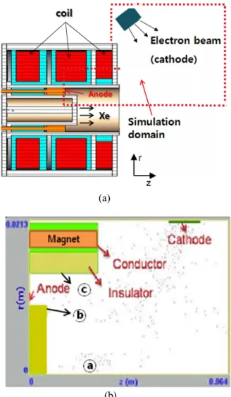
Fig. 1. Shown are (a) the scheme of the considered Hall thruster and (b) the simulation domain.
II. Description of the model
A. Simulation Domain and Particle Trajectory Figure 1 is the scheme of the considered Hall thruster. The simulation assumes axial symmetry at r=0 planes and the position of cathode can be changed
557
AJCPP 2008 March 6-8, 2008, Gyeongju, Korea
by the injection of electron beam. For this study, we consider the real size of the cylindrical Hall thruster fabricated in Korea Advanced Institute of Science and Technology. The inner radius and the channel length are 14mm and 24mm, respectively. By now, the thruster has a performance of 8.4 mN thruster and 35% thrust efficiency at 200 W. The Hall thruster consists of an anode between insulators and dielectric, a cathode for the electron beam injected, magnet coils inside of the conductor, and an empty channel for the xenon accelerated. The dielectric wall is taken into account by introducing the constant of second electron emission coefficient (SEEC). The magnetic field profiles are calculated from the coil geometry with the Poisson super fish code.
The electron trajectory follows the magnetic field line. In addition, E×B drift also plays an important role in the particle transport. When the position of cathode is shifted, the trajectory of electrons is rapidly changed.
B. Direct simulation of Molecular Dynamics for Neutrals
(a)
(b)
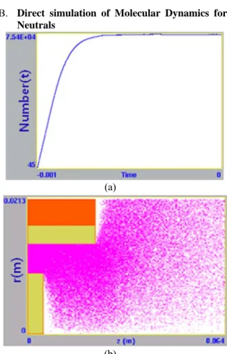
Fig. 2. The simulation results are shown for (a) the time evolution of the number of neutral Xe and (b) the
position space profile of neutral Xe particles.
It is necessary to simulate the molecular dynamics of the Xe neutral particles to simulate the acceleration channel accurately. As Xe gas enters from the hole at the anode into the cylinder, the gas is diffused into the domain. It cannot be simulated with the Navier-stroke equation because the Knudsen number is very large for this low pressure regime. A two-dimensional
molecular dynamics code has been developed and combined with the PIC-MCC Hall thruster code. The time to make steady state of molecular dynamics is almost 10 ms as shown in Fig. 2(a). When the molecular dynamics of the neutrals reaches steady state, the density, gas pressure, and temperature of the neutrals are calculated as shown in Fig 3.
(a)
(b)
(c)
Fig. 3. The simulation results are shown for (a) neutral density, (b) gas pressure, and (c) neutral
temperature.
The control parameters of the injected neutral gas are the mean velocity and the gas flow rate. The neutral density is an important factor for discharge. If the density is small, the mean free path of electrons
558
AJCPP 2008 March 6-8, 2008, Gyeongju, Korea
becomes large, which means that the discharge is hard to be generated in the Hall thruster. On the contrary, if the density is too high, collision happens very frequently. In this case, the effectiveness of B-field is smaller, and it is difficult to confine the plasma as ω
cτ
«1, where ω
cis the electron cyclotron frequency and τ is the average collision time.
C. Particle-in-Cell Simulation for Charged Particles
The PIC simulation scheme is the same as the well- known method developed in the Plasma Theory and Simulation Group of the University of California at Berkeley
3-4. The particle motion is calculated using the Boris method in r-z coordinates. The Successive- over-relaxation Extra-Jacobi (SOR-EJ) method is used for the calculation of the Poisson equation of the electrostatic potential. The secondary electron emission effect on the dielectric layer is also considered
5-6.
D. Monte Carlo Collision Model (MCC)
Mont Carlo Collision (MCC) model is coupled with the molecular dynamics model for the neutral density.
The MCC model of Hall thruster is easy to parallelize the simulation code because it is adopted to calculate the direct method instead of the null collision. The MCC model does not assume the velocity distributions of the particles. As the time scale of MCC is much shorter than the steady state time of neutral particles; the neutrals can be assumed to be stationary compared with the plasma motion during MCC collisions.
7III. Simulation Results
With the variation of the position of the cathode, the position of the electron beam emitter in the simulation domain is changed. Thus, the trajectory of the electron beam is changed for a given magnetic field profile. It is necessary to have a proper electron beam injection for an efficient discharge of the Hall thruster. Fig. 3 shows the trajectories of electrons under the considered magnetic fields. Here, the collision of electrons with the neutral gas is not included in this trajectory calculation for simplicity.
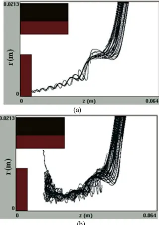
As shown in Fig. 3, the electron trajectory follows the magnetic field line. In addition, E×B drift also plays an important role it the particle transport. Figs.
4(a) and 4(b) are the electron trajectory for different magnetic field profiles at the same injection position and with beam energy of 1.1 eV. It was also observed that large amount of electron beams are reflected by the magnetic field profile.
(a)
(b)
Fig. 4. Electron trajectory with different magnetic field profiles.
(a)
(b)
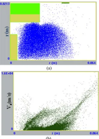
Fig. 5. Shown are (a) the time evolution of particle numbers and (b) a temporal potential profile at 0.01
ms.
559
AJCPP 2008 March 6-8, 2008, Gyeongju, Korea
Figure 5 shows a typical result with an applied voltage of 250 V and with the electron current density of 2 A/m
2with beam energy of 1.1 eV. The number of cells is 42 by 128, and the time step is 20 ps. The density profile of Fig. 3(a) is used for the background gas density. The simulation did not reach steady state yet at this time. As time goes on, the number of electrons and ions increases inside the acceleration channel. As the electron loss is much faster than the ion loss, the electrostatic potential inside of the acceleration channel increases. Therefore, the injected electron beam experiences acceleration and ionization process and is accelerated.
(a)
(b)
Fig. 6.