2014 한국유체기계학회 학술대회 발표 논문, 2014년 11월 26-28일, 부산
◎ Original Paper
ISSN (Print): 2287-9706
운전조건에 따른 펌프 터빈 시스템의 안정성 연구
천청청*⋅패트릭마크싱*⋅최영도**†1)
Reliability Investigation of a Pump-Turbine System at Various Operating Conditions
Chengcheng Chen*, Patrick Mark Singh*, Young-Do Choi**†
Key Words : Pump-turbine(
펌프 터빈), Off-design(
비설계점), Impeller(
임펠러), Stress(
응력), FSI analysis(
유체-
구조연성 해석) ABSTRACT
Pump-turbine system is widely used by the hydropower industry for stabilizing the electrical grid in the vast growing economy of most developed countries. This study only investigates the Fluid-structure Interaction (FSI) analysis of the pump-turbine system at various operating conditions. The FSI analysis can show how reliable each component of the system is by providing the engineer with a better understanding of high stress and deformation points, which could reduce the lifespan of the pump-turbine. Pump-turbine components are categorized in two parts, pressurized static parts and movable stressed parts.
The fixed parts include the spiral casing, top and bottom cover, stay vane and draft tube. The movable parts include guide vanes and impeller blades. Fine hexahedral numerical grids were used for CFD calculation and fine tetrahedral grids were used for structural analysis with imported load solution mapping greater than 90 %. The maximum equivalent stress are much smaller than the material yield stress, and the maximum equivalent stress showed an increasing tendency with the varying of operating conditions from partial to excessive at both modes. In addition, the total deformation of all the operating conditions showed a small magnitude, which have quite small influence on the structural stability. It can be conjectured that this system can be safely implemented.
1. Introduction
Pump-turbine system is widely used by the hydropower industry for stabilizing the electrical grid in the vast growing economy of most developed countries. Korea has pump storage plants in seven locations with total generating capacity of 4.7 GW(1). The system has an impeller which pumps water to an upper reservoir during the night and the same impeller acts as a runner for turbine mode during the day.
One of the most important requirements of pump-
turbines is high efficiency. To design pumps with high efficiency there are many things that needs to be considered, such as performance, internal flow, reliability and cavitation analysis among the common ones. However, this study only investigates the Fluid- structure Interaction (FSI) analysis of the pump- turbine system at various operating conditions.
H bner et al. conducted studies on application of fluid-structure coupling to predict the dynamic behavior of turbine components(2). The FSI analysis can show how reliable each component of the system is by
* Graduate School, Department of Mechanical Engineering, Mokpo National University, Mokpo
** Department of Mechanical Engineering, Institute of New and Renewable Energy Technology Research, Mokpo National University, Mokpo
† 교신저자, E-mail : [email protected]
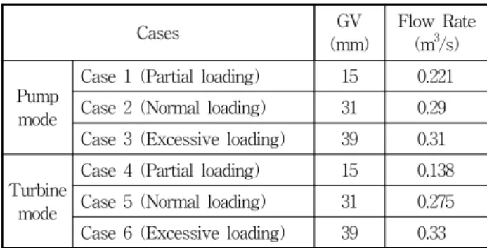
Parameter Value
Young’s modulus (GPa) 193
Poisson’s ratio 0.288
Tensile yield strength (MPa) 207
Tensile Ultimate strength (MPa) 580 Table 1. Material Properties of impeller (13Cr4Ni)
Static Structural
Analysis
Supports Fixed
Impeller Rotating
Contacts connection No separation
FSI Analysis Imported solution CFX-Fluid flow
Imported load Pressure
Table 3. Numerical methods and conditions Fig. 1 Plan view of pump-turbine mode
Fig. 2 Numerical grid for CFD analysis
Fig. 3 Numerical grid of the pump-turbine system for static structural analysis
Turbine
mode Case 5 (Normal loading) 31 0.275 Case 6 (Excessive loading) 39 0.33
providing the engineer with a better understanding of high stress and deformation points, which could reduce the lifespan of the pump-turbine.
2. Pump-turbine model and Numerical methods
2.1 Pump-turbine Model
The plan view of the pump-turbine system can be seen in Fig. 1. For this study there are 7 blades, 19 stay vanes and 20 guide vanes in total. The pump- turbine has
H
= 32 m,Q
= 0.336 m3/s andN
= 1200 min-1.Pump-turbine components are categorized in two parts, pressurized static parts and movable stressed parts. The fixed parts include the spiral casing, top and bottom cover, stay vane and draft tube. The movable parts include guide vanes and impeller blades.
The operating condition and requirements for pump- turbine impeller includes high velocity, two operating modes, prone to cavitation, corrosion and sand erosion.
Therefore, it is recommended to use martensite low carbon stainless steel (13Cr4Ni)(3). Material properties are shown in Table 1.
2.2 Numerical methods
The result of Computational Fluid Dynamics (CFD)
analysis shows the internal flow on the pump-turbine fluid domain, giving a description of hydrodynamic characteristic of the pump-turbine system. The static structural analysis is carried out by using the CFD results as the input load condition, which when combined is known as Fluid Structure Interaction analysis (FSI). Similar methods have been referred that were conducted by Xiao(4) and Rama(5) et al. The FSI analysis were performed by combining the CFD
Fig. 4 Boundary condition for FSI analysis
Fig. 5 CFD validation test according to different element numbers
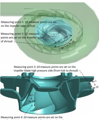
and turbulence models Fig. 6 Measuring points 1 to 4 on the impeller blade
analysis results in ANSYS CFX and structure analysis in ANSYS static structural(6).
Table 2 shows the varying operating conditions for the simulations and Table 3 presents the numerical methods. In addition, the numerical grid and boundary conditions also further explained with Figs. 2 to 4. The impeller is the only rotating component in both directions, whereas all other components are fixed.
The natural gravitational force is also applied.
Fine hexahedral numerical grids were used for CFD calculation and fine tetrahedral grids were used for structural analysis with imported load solution mapping greater than 90 %. Mesh dependence test and turbulence model dependence tests were also carried out as shown in Fig. 5. Shear stress transport (SST) model was utilized for all final calculations and input condition for FSI analysis.
A single impeller was selected randomly to study the stress and deformation in detail. Four measuring locations were identified as shown in Fig. 6. Measuring point 1 consisting of 32 measuring points set on the impeller edge at the hub. Measuring point 2 consisting of 32 measuring points set on the impeller edge at the shroud. Measuring point 3 consisting of 20 measuring
points set on the impeller blade high pressure side from hub to shroud. Measuring point 4 consisting of 20 measuring points set on the impeller blade low pressure side from hub to shroud.
3. Results and Discussion
3.1 Overall stress and deformation on pump-turbine system
The maximum equivalent stress and total deformation of impeller and guide vane at different operation condition are summarized in Fig. 7. It indicates that the maximum equivalent stress are much smaller than the material yield stress, and the maximum equivalent stress shows a increase tendency with the changing of operating condition from partial to excessive at both modes. In addition, the total deformation of all the operating condition shown in a quite small magnitude which have quite small influence on the structural stability.
The result of overall structure FSI analysis at the normal operating condition are presented by equivalent stress and total deformation in Figs. 8 and 9. The
(a) Stress distribution
(b) Deformation distribution
Fig. 7 The maximum stress and deformation on the impeller and guide vane according to different operating conditions for both
pump and turbine modes
(a) Stress distribution (b) Deformation distribution Fig. 8 The overall stress and deformation distribution for Case 2 in
pump mode
(a) Stress distribution (b) Deformation distribution Fig. 9 The overall stress and deformation distribution for Case 5 in
turbine mode
(a) Stress distribution (b) Deformation distribution Fig. 10 Maximum stress and deformation on impeller for Case 3 in
pump mode
(a) Stress distribution (b) Deformation distribution Fig. 11 Maximum stress and deformation on impeller for Case 6 in
turbine mode
large stress appears in the connection of guide vaneand casing, and also the impeller blade. The stress distribution indicates the relatively weak region is guide vane shaft and impeller blade tip. In addition, the distribution of stress and deformation shown in both modes are in a similar area.
3.2 Investigation of stress and deformation distribution on the impeller
The maximum stress on impeller appears at the connection of impeller blade and hub, at every operating condition of both modes. The maximum deformation of pump mode appears at the medium of blade low pressure side in partial loading condition, and moves to the shroud of impeller high pressure side in normal and excessive loading condition. For turbine mode, the maximum deformation also appears at the medium of blade high pressure side in partial loading condition, and moves to the shroud of impeller high
pressure side in normal and excessive loading condition. The maximum stress and deformation for both modes are presented in Figs. 10 and 11, both appearing in the excessive loading.
(a) Measuring point 1
(b) Measuring point 2
(c) Measuring point 3
(d) Measuring point 4
Fig. 13 The investigation of stress on impeller blade in turbine mode
(a) Measuring point 1
(b) Measuring point 2
(c) Measuring point 3
(d) Measuring point 4
Fig. 12 The investigation of stress on impeller blade in pump mode
3.3 Comprehensive investigation of stress and deformation on a single impeller blade and guide vanes
Figs. 12 to 15 show more detail presentation of stress and deformation at the four measuring locations
of the impeller blade in the operating conditions of partial, normal and excessive loading. The figures show the periodic jump of stress and deformation in the impeller edge of hub and shroud, which are caused by the periodic distribution of impeller blade. In addition, the value of stress and deformation present a similar trend that the maximum value appears in the
(a) Measuring point 1
(b) Measuring point 2
(c) Measuring point 3
(d) Measuring point 4
Fig. 14 The investigation of deformation on impeller blade in pump mode
(a) Measuring point 1
(b) Measuring point 2
(c) Measuring point 3
(d) Measuring point 4
Fig. 15 The investigation of deformation on impeller blade in turbine mode
operating condition of excessive loading in contrast to normal and partial loading.
It can be observed that measuring points 1 and 2 show similar trends and do not show significant changes in contrast to measuring points 3 and 4, which show a rising trend at the ends and falling trend at the center. As shown in Figs. 12(c) and 13(c), the
stress in the two ends (location No. 1, 19 and 20 of measuring point 3) of impeller blade high pressure side are higher than the central locations. However, the stress distribution on the blade lower pressure side shows a different tendency, a peak appears near three-quarters of the abscissa(location No. 14 to 16 of measuring point 4), as shown in Figs. 12(d) and 13(d).
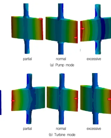
partial normal excessive (a) Pump mode
partial normal excessive (b) Turbine mode
Fig. 16 The investigation of stress on impeller blade
partial normal excessive (a) Pump mode
partial normal excessive (b) Turbine mode
Fig. 17 The investigation of deformation on impeller blade
The deformation on the high and low pressure side of impeller blade shows a similar tendency that the deformation have a peak in the center of the blade side, as the curves shown in Figs. 14(c) and 15(c).
As shown in Fig. 16, the maximum stress on the guide vane are located in almost the same position, the shaft used for connecting the guide vane. Figure 17 shows that the deformation of guide vane is not uniform in every guide vane of pump mode, especially the normal and excessive loading. In contrast, the deformation in every guide vane of turbine mode is almost same among the three operating conditions.
4. Conclusions
From this study, it was observed that this pump- turbine system showed very low stresses and deformation from the FSI analysis results. Region of stress concentration of the overall system is located in the connection of impeller blade and impeller hub, also the connection of guide vane and casing. Note, the deformation of guide vane is not uniform in every guide vane of pump mode. In contrast, the deformation situation in every guide vane of turbine mode is almost
same among the three operating conditions. It can be conjectured that this system can be safely implemented.
References