INTRODUCTION
The improvement of radiotherapy techniques and the de-velopment of new devices are some of the important factors in trying to achieve the therapeutic goal. The goal of radio-therapy is to minimize damage to the critical organs and other normal tissue and maximize the target dose. A wide range of therapeutic techniques, including 4-dimensional conformal radiotherapy(4D-CRT), intensity modulation radiation
ther-apy(IMRT), image-guided radiation therapy(IGRT), and respiratory gated radiation therapy(RGRT), have recently been applied. These therapeutic techniques artificially trans-form a dose distribution in a range of positions, such as the patient’s body surface correction and the irregular shape of a tumor, with the aim of optimizing the dose distribution for the tumor and minimizing that for normal tissues(Oh et al. 1996; Marks et al. 2010). Bolus, tissue compensating filters, and wedge filters are commonly used to transform the dose distribution artificially; of these, wedge filters are used most widely in clinical practice. For wedge filters, either a physi-cal wedge, which partially reduces the intensity of the
radi-Dose Volume Histogram Analysis for Comparison of
Usability of Linear Accelerator Flattening Filter
Yun-Sang Ji1, Kyung-Rae Dong1,*, Jae-Kwang Ryu2,Ji-Won Choi3 and Mi-Hyun Kim1,4
1Department of Radiological Technology, Gwangju Health University, 73, Bungmun-daero 419 beon-gil, Gwangsan-gu, Gwangju 62271, Republic of Korea
2Depatment of Nuclear Medicine, Asan Medical Center, 88, Olympic-ro 43-gil, Songpa-gu, Seoul 05505, Republic of Korea
3Department of Radiological Science, Jeonju University,
303, Cheonjam-ro, Wansan-gu, Jeonju-si, Jeollabuk-do 55069, Republic of Korea 4Department of Radiation Science & Technology,
Graduate School of Chonbuk National University,
567 Baekje-daero, Deokjin-gu, Jeonju-si, Jeollabuk-do 54896, Republic of Korea
Abstract - The wedge filter has two movements, fixed and dynamic. In this study, the depth dose distribution was analyzed to determine the stability of the dose distribution and dose volume histo-grams obtained by evaluating the usability of the critical normal tissue dose around the tumor dose. The depth dose was analyzed from the dose distribution from a Linac(6 MV and 10 MV irradia-tion field of energy 20×20cm2, wedge filter with a SSD of 100cm and 15°, 30°, 45° Y1-in(Left -7
cm), Y2-out(Right +7cm). To analyze the fluctuations of the depth dose, a fixed wedge and dynam-ic wedge toe portion was examined according to the energy and angle because the size of the fluctu-ations was included in the error bound and did not show significant differences. The neck, breast, and pelvic dosimetry in tumor tissue are measured more commonly with a dynamic wedge than a fixed wedge presumably due to the error range. On the other hand, dosimetry of the surrounding normal tissue is more common using a fixed wedge than with a dynamic wedge.
Key words : Wedge filter, Neck, Breast, Pelvic, Dosimetry
─ 297 ─ Technical Paper
* Corresponding author: Kyung-Rae Dong, Tel. +82-62-958-7668, Fax. +82-62-958-7669, E-mail. [email protected]
ation output depending on the angle of the absorber, or a dynamic wedge, which produces a wedge-shaped dose dis-tribution with the automatic movement of a collimator by the change in dose rate, dose, or the velocity of the collimator during irradiation is used(Cheng and Chin 1987). A physi-cal wedge is used to obtain a dose distribution at the desired angle by placing a metal wedge at the beam center. The dose distribution is characterized physically by the beam harden-ing effects and by the reduction in radiation output due to unnecessary scattering of rays caused by the metal object. A dynamic wedge may generate no beam hardening effect because an isodose distribution is formed based on the dose rate and the movement of the collimator. No change in the properties of the beam, and the dose is reduced as the irradi-ation surface area becomes larger(Klein et al. 1995; Li and Klein 1997).
Although physical and dynamic wedges, both of which have unique physical properties, are frequently used in clin-ical practice, the latter has recently been used in more cases. A dynamic wedge carries no risk of the gantry conflicting with the patient during treatment and causes no reduction in output without a reduction of the wedge itself because no metal material is used. This may also reduce the unnecessary surface dose because of the low dose in other areas than the irradiation surface. This study compared the stability of the physical and dynamic wedges through dose measurements based on their angle, and applied two wedge filters to clini-cal treatment sites to obtain a dose-capacity histogram, ana-lyze the target dose and the dose for the important normal tissues, and determine their usefulness.
MATERIALS AND METHODS
1. Instrument and materials
A Linac 21I(Varian, U.S.A) was used and a dose-volume- capacity graph was obtained using a CT-simulator(General Electrics) and treatment planning system eclipse Ver. 8.6 (Varian, U.S.A) according to the therapy plan. The dose was measured using a dosimeter(Wellhofer-Scanditronix, Farmer Type Chamber) and a physical wedge(15, 30, and 45) (Vari-an, U.S.A). An Alderson Rado was used as a phantom.
2. Methods
The depth dose was measured 3cm deep on a 20×20cm2
irradiation surface from SSD 100cm in a dose of 100-mon-itor units for an X-ray energy of 6MV and 10MV. Compar-ative analysis of the changes in physical and dynamic wedge filters with 6MV and 10MV energy using the data from 10 sessions of measuring the physical and dynamic wedge at IN(Y1, -7cm) and OUT(Y2, +7cm) points of the wedge filters was made. A comparative analysis of the CV values in the data obtained at the angles of 15°, 30°, and 45° was made. Clinical application was made to the neck(15°), breast(30°), and pelvic(45°) regions to obtain a dose-volume histogram for radiotherapy and analyze the target dose and the dose for the surrounding important normal tissues.
RESULTS
1. Analysis of the dose by variation in energy and angle
As shown in Table 1, for the variation of the charge from the toe to the heel at several angles of the wedge for 6MV energy, the dynamic wedge generated 1.337, 2.398, and 3.375, respectively, and the physical wedge generated 1.049, 1.743, and 2.440, respectively. The former generated a 2.888, 0.655, and 0.935 greater charge, respectively, than the latter.
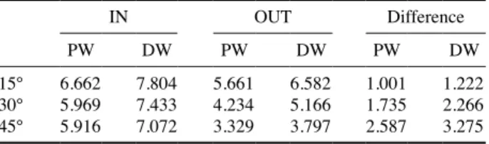
As shown in Table 2, for the variation in charge from the toe to the heel at several angles of the wedge for a 10MV energy, the dynamic wedge generated 1.222, 2.266, and 3.275, respectively, and physical wedge generated 1.001, 1.735, and 2.587, respectively. The former generated a 0.221, 0.531, and 0.688 larger charge, respectively, than the latter.
Table 1. 6MV energy value of the wedge filter change lay
IN OUT Difference
PW DW PW DW PW DW
15° 6.048 7.300 4.999 5.963 1.049 1.337
30° 5.289 6.891 3.546 4.493 1.743 2.398
45° 5.305 6.520 2.865 3.145 2.440 3.375
The unit is the nC.
Table 2. 10MV energy value of the wedge filter change lay
IN OUT Difference
PW DW PW DW PW DW
15° 6.662 7.804 5.661 6.582 1.001 1.222
30° 5.969 7.433 4.234 5.166 1.735 2.266
45° 5.916 7.072 3.329 3.797 2.587 3.275
2. Analysis of the dose variation coefficient by variation in energy and angle
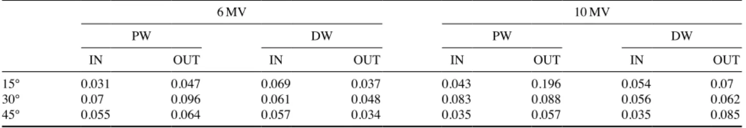
As shown in Table 3, at a 15° wedge with a 6MV energy, the dynamic wedge generated a 0.038 higher coefficient of variation than the physical one in the toe and the latter gen-erated a 0.01 higher coefficient of variation than the former in the heel. At the 30° wedge, the physical wedge generated a 0.009 higher coefficient of variation than the dynamic one in the toe, and the former generated a 0.048 higher coeffici-ent of variation than the latter in the heel. At the 45° wedge, the dynamic wedge generated a 0.002 higher coefficient of variation than the physical one in the toe and the latter gen-erated a 0.03 higher coefficient of variation than the former in the heel. In terms of the energy and the angle, the dynamic wedge generated a slightly higher coefficient of variation in the toe and the physical one generated a higher coefficient of variation in the heel but this was within the margin of error. The variation in the dose was insignificant within the margin of error.
As shown in Table 3, at the 15° wedge with a 6MV energy, the dynamic wedge generated a 0.011 higher coefficient of variation than the physical one in the toe and the latter gen-erated a 0.126 higher coefficient of variation than the former in the heel. At the 30° wedge, the physical wedge generated a 0.027 higher coefficient of variation than the dynamic one in the toe and the former generated 0.026 higher coefficient of variation than the latter in the heel. At the 45° wedge, the dynamic and physical wedges generated the same variation in the toe and the latter generated a 0.03 higher coefficient
of variation than the former in the heel.
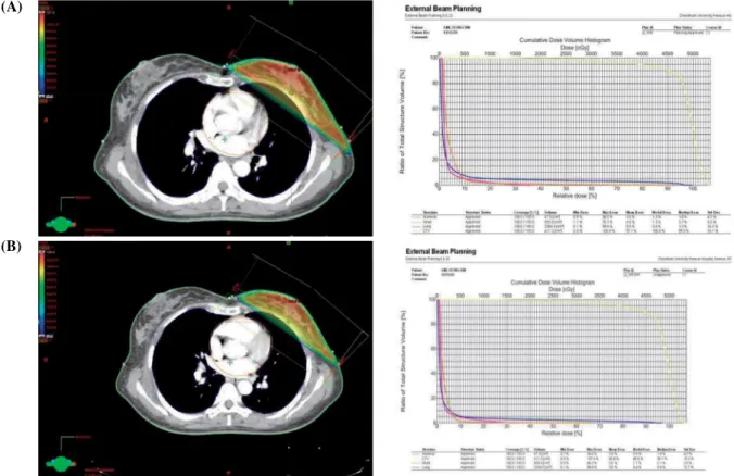
As listed in Table 4, the wedge in neck(15°), breast(30°), and pelvic(45°) regions was used to make a CT treatment plan, obtain a dose-volume histogram for radiotherapy, and make comparative analysis of the GTV and CTV values bet-ween the physical and dynamic wedges. A higher target dose was irradiated from the dynamic wedge(Figs. 1~3).
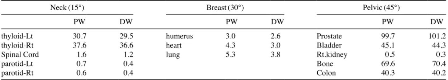
As listed in Table 5, the dose-volume histogram showed that the dynamic wedge generated a lower dose for normal tissues surrounding the tumor than physical one.
DISCUSSION
A wedge filter is used to make a uniform dose distribution with an isodose curve to achieve the therapeutic effects. In clinical practice, physical and dynamic wedges are used. A physical wedge is placed at the beam center to obtain a dose distribution at the desired angle and promote the therapeutic effects and can be varied by the irradiation surface area. This is characterized physically by the following: the beam hard-ening effects, the variation in the angle of the wedge by depth, the decrease in radiation output due to the constant output, and the generation of scattering rays. The dynamic wedge, which is used to generate a dose distribution by changing the dose rate and speed of the collimator, may not reduce the radiation dose, rarely generates scattering rays, and make the angle of wedge vary with depth(Cumberlin et al. 1989; Prabhakar et al. 2007). This can be applied to a larger irra-diation surface than the physical one and make it possible to obtain an isodose distribution at diverse angles. The dynam-ic wedge may generate a higher depth dose under identdynam-ical conditions, require longer treatment duration, and make a dose calculation more complicated than physical one. The dynamic wedge is unaffected by the irradiation surface; rapid changes are observed in all the output factors as the angle of the dynamic wedge become large because the dynamic
Table 3. 6MV, 10MV as to the changing angle to CV values of PW, DW
6MV 10MV
PW DW PW DW
IN OUT IN OUT IN OUT IN OUT
15° 0.031 0.047 0.069 0.037 0.043 0.196 0.054 0.07
30° 0.07 0.096 0.061 0.048 0.083 0.088 0.056 0.062
45° 0.055 0.064 0.057 0.034 0.035 0.057 0.035 0.085
Table 4. Body part of tumor tissue dose comparison
Neck(15°) Breast(30°) Pelvic(45°)
PW DW PW DW PW DW
GTV 103.8 104.7 99.4 100.0
CTV 102.1 102.9 97.1 96.8 99.6 100.2
Fig. 1. Neck(15°) by applying the fixed wedge(A), dynamic wedge(B) comparison. (A)
(B)
Fig. 2. Breast(30°) by applying the fixed wedge(A), dynamic wedge(B) comparison.
(A)
wedge does not have each segment move immediately as the dose is delivered to the irradiation surface but generates a valid angle of the wedge by delivering the remaining dose as the wedge moves after the delivery based on the angle, dose rate, and dose, which are determined at certain time intervals (Kijewski et al. 1978; Petti and Siddon 1985). Regarding the dose for 6MV and 10MV energy, the dynamic wedge may generate a steeper depth dose distribution curve than the phy-sical one. This is because the greater energy and the greater angle of the wedge, the higher dose rate for each segment to maintain a valid angle of the dynamic wedge(Khan et al. 1986; Cross et al. 1992). The penumbra field of the dynam-ic wedge was narrower than that of the physdynam-ical one in the
left side of the radiation therapy field; approximately 4% error in the penumbra was found between the internal right and left sides and the external ones of the dynamic wedge at the angle of 45° with 6MV and 10MV, and the error ranged from approximately 1% to 3% at other angles. The use of the outer part of the actual irradiation surface, or normal physi-cal wedge or general shielding block, may deliver a lower dose to the shielded part other than the irradiation surface; specifically, the target dose may increase within the treat-ment plan capacity when performing radiotherapy.
Although the physical properties and strong and weak points of the wedge are important factors when choosing between physical and dynamic wedges, it seems more
rea-Fig. 3. Pelvic(45°) by applying the fixed wedge(A) dynamic wedge(B) comparison.
(A)
(B)
Table 5. Body part of surrounding normal tissue dose comparison
Neck(15°) Breast(30°) Pelvic(45°)
PW DW PW DW PW DW
thyloid-Lt 30.7 29.5 humerus 3.0 2.6 Prostate 99.7 101.2
thyloid-Rt 37.6 36.6 heart 4.3 3.0 Bladder 45.1 44.3
Spinal Cord 1.6 1.2 lung 5.3 3.8 Rt.kidney 0.5 0.3
parotid-Lt 0.7 0.4 Bone 69.6 70.4
parotid-Rt 0.6 0.4 Colon 40.3 40.2
sonable to analyze the target dose for the patient and the dose of the surrounding normal tissues through a dose-vol-ume histogram in clinical practice.
CONCLUSION
The dynamic wedge generated slightly greater variation in charge by the energy and the angle than the physical one. This suggests that the dynamic wedge is more unstable than the physical one; however, there is no significant difference in stability when performing treatment because the variation width between the two types of wedge is within the margin of error. Histograms for the neck, breast, and pelvic regions were derived from the treatment dose plans to compare the target dose and the dose for the critical organs. The dynamic wedge generated a higher radiation dose to the tumor tissues than the physical one and the latter generated a higher radi-ation dose to surrounding important normal tissues than the former. Therefore, the former is more useful than the latter. These characteristics are important to consider regarding the objective of protecting critical organs when applying a wedge to clinical practice.
REFERENCES
Cheng CW and Chin LM. 1987. A computer-aided treatment planning technique for universal wedges. Int. J. Radiat.
Oncol. Biol. Phys. 13(12):1927-1935.
Cross P, Joseph DJ, Cant J, Cooper SG and Denham JW. 1992.
Tangential breast irradiation: simple improvements. Int. J.
Radiat. Oncol. Biol. Phys. 23(2):433-442.
Cumberlin RL, Dritschilo A and Mossman KL. 1989. Carcino-genic effects of scattered dose associated with radiation ther-apy. Int. J. Radiat. Oncol. Biol. Phys. 17(3):623-629. Khan FM, Gerbi BJ and Deibel FC. 1986. Dosimetry of
asym-metric x-ray collimators. Med. Phys. 13(6):936-941. Kijewski PK, Chin LM and Bjärngard BE. 1978. Wedge-shaped
dose distributions by computer-controlled collimator motion.
Med. Phys. 5(5):426-429.
Klein EE, Low DA, Meigooni AS and Purdy JA. 1995. Dosim-etry and clinical implementation of dynamic wedge. Int. J.
Radiat. Oncol. Biol. Phys. 31(3):583-592.
Li Z and Klein EE. 1997. Suface and peripheral doses of dynam-ic and physdynam-ical wedges. Int. J. Radiat. Oncol. Biol. Phys.
37(4):921-925.
Marks LB, Yorke ED, Jackson A, Ten Haken RK, Constine LS, Eisbruch A, Bentzen SM, Nam J and Deasy JO. 2010. Use of normal tissue complication probability models in the clinic. Int. J. Radiat. Oncol. Biol. Phys. 76(3):10-19. Oh YT, Keum KC, Chu SS and Kim GE. 1996. Dosimetric
char-acteristics of dynamic wedge technique. J. Korean Soc. Ther.
Radial. Oncol. 14(4):1996:323-332.
Petti PL and Siddon RL. 1985. Effective wedge angles with a universal wedge. Phys. Med. Biol. 30(9):985-991.
Prabhakar R, Julka PK, Malik M, Ganesh T, Joshi RC, Sridhar PS, Rath GK, Pant GS and Thulkar S. 2007. Comparison of contralateral breast dose for various tangential field techni ques in clinical radiotherapy. Technol. Cancer Res. Treat.
6(2):135-138.
Received: 14 September 2018 Revised: 30 September 2018 Revision accepted: 10 November 2018