ICCAS2005 June 2-5, KINTEX, Gyeonggi-Do, Korea
Development of PSD Sensor Based Range Finder System
Using Linearizing Function of Voltage-Distance Conversion
*Yu-Chan Kim, *Young-Jae Ryoo, **Jeong-Gon Song, **Ju-Sang Lee
*Department of Control System Engineering, Mokpo National University, Korea **Department of Electrical Engineering , Chonnam National University, Korea(Tel : +82-61-450-2754; E-mail: [email protected]) (Tel : +82-61-450-2754; E-mail: [email protected])
Abstract: In this paper, the range finder system using a PSD sensor suitable for low-cost localization sensor of a mobile robot.
Because the distance-voltage output of a PSD sensor has a non-linear property, the linearizing function is proposed through the experimental characteristics of the sensor. And the characteristics are tested and the distance-voltage data are measured in various colors and materials of object. For a known environment, a mobile robot scans the surroundings using a PSD sensor that can rotate 360˚. Finally, the performance and accuracy of the developed system are verified according to the comparison the distance by proposed function with real distance
Keywords: PSD sensor , range finder system, linearizing function, Scan
1. INTRODUCTION
Recent, intelligent robot industrial is specified to national growth industry, so there would be political and industrial support continuously. Especially, home service robot has world wide market and related enterprises are trying to product as soon as possible[1,2]. There are many kind of robots; cleaner robot, errand robot, housework robot, guard robot, etc. For supply of such robots, low cost localization system would be taken up the most important part.
There are two positioning system, that are relative positioning system and absolute positioning system. There are two representative methods, one is encoder that obtains the distance and direction by measure the number of revolution of the motor, the other is gyroscope that can compensate the angle of direction with angular velocity[3]. At first, encoder has weak point that is angle of direction errors are accumulated while robot is moving and causes increasement of positioning error. Gyroscope is expensive, and performs integral calculus to determine position but, some error that happens while performing causes critical positioning error. So absolute positioning system is used to overcome these weak points in relative positioning system.
There are several methods that is to build the map and obtain the distance information with ultrasonic sensor or image from camera[4]. Measurement resolution of ultrasonic sensor is not good, so reflected wave signal from each obstacle makes large error. To use camera requires expensive devices to process the images. Once more, it takes so many times to process images, and so real-time processing is difficult.
To improve these weak points, method using PSD sensor is being researched[5]. This method extracts distance information to PSD sensor. PSD has 2 dimensional structure and very expensive, so development of distance measurement method using PSD that has 1 dimensional structure is required. But this sensor has nonlinear characteristic in voltage output.
So in this paper, extract linearizing function from PSD sensor that has nonlinear characteristic. And suggest range
finder system that can scan while rotate 360˚.
The first thing to realize the system is analyze the non-linear characteristic of PSD and obtain voltage output according to the distance. Secondly, build linearizing voltage vs. distance conversion function and each coefficient with obtained data. Next, compose range finder system, and apply linearizing function so that obtain distance vs. voltage value. Lastly, supply this, build environmental map through 360˚ rotation, and valuate the performance.
2. CHARACTERISTIC OF PSD SENSOR
2.1 Principle of PSD sensor
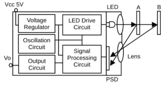
The Fig. 1 shows the principle of PSD sensor. The infrared is diffused by LED drive circuit and then it is incidence into IR receiver of PSD to reflect from obstacle. The PSD sensor make a signal to use principle which is that the infrared reflected from substance A and B.
Fig. 1 Principle of PSD sensor.
2.2 Characteristic of PSD sensor
In this paper, used for experiment is. Distance from 20~150[cm] can be measured with this sensor. Fig.2 shows the characteristic of sensor. Characteristic of distance vs. output is shown as non-linear. Such non-linearity is not standard for output voltage according to real distance. So, linearizing distance vs. voltage conversion function is needed for improving. A B PSD LED LED Drive Circuit Signal Processing Circuit Vcc 5V Voltage Regulator Oscillation Circuit Lens Output Circuit Vo
1427
ICCAS2005 June 2-5, KINTEX, Gyeonggi-Do, Korea
Fig. 3 Deriving procedure of conversion function.
0 0.5 1 1.5 2 2.5 3 0 20 40 60 80 100 120 140 160 Distance [cm] O u tput V o ltage [V ]
. White Paper
3. COMPOSITION OF RANGE FINDER SYSTEM
3.1 Structure of distance measuring system
Fig.4 shows whole structure of realized range system. Measured consecutive scan data input from PSD sensor. Signals are amplified and then converted into digital value by A/D converter. Lastly, Converted value is applied to the voltage vs. distance linearizing function, and so environmental map is built.
Fig. 2 Output characteristic of PSD sensor.
Amplifier
2.3 Linearizing distance vs. voltage conversion function
Fig.3 represents processing of derived linearizing conversion according to voltage vs. distance. At first, obtain the distance vs. voltage data through the experiment. Fig.2 shows that characteristic curve has inverse-proportion characteristic in a range between 20cm and 150cm that is measured to sensor. Accordingly we want to conversion from the property of inverse-proportion to property of linear.
A/D Converter
Voltage to Distance Conversion
First, we define an inverse-proportion equation of sensor;
) ( 1 K D V + = (1)
V=output voltage, D= Distance, K= error.
In here, 'V' means output voltage, 'D' means distance, and 'K' means coefficient error. The inverse characteristic equation can be represented to rectilineal equation
(
y
=
m
×
x
+
b
)
and represented: b V m K D+ ) = × + ( 1 (2) m=Gradient, b= Y intercept.Model (2) can be arranged for distance, and then can be represented like: K b m V D − + × = ) ( 1 (3)
For using the derived function, appropriate coefficient m, b, K should be fixed. These values can be extracted LMS(Least Mean Square) rule that using measured data.
PSD Scan Data
Mapping
Fig. 4 Structure of range finder system.
3.2 Composition of range finder system
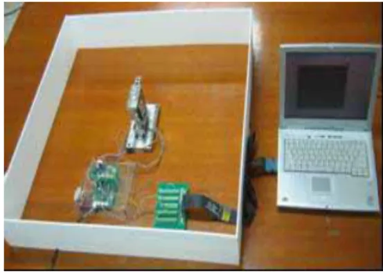
The Fig. 4 is hardware composition device of PSD based range finder system that is realized. Structure for consecutive scanning with 360˚ rotation was made. Set up the wall of square of which length and width is 40cm, for obtaining data from environment. User interface program was written by LabVIEW. And DAQCard-6062E was used for A/D converting.
Fig. 5 Developed range finder system.
4. ANALYSIS OF EXPERIMENT RESULT
4.1 Output characteristics according to color and quality of the obstacle
For grasping the output change of PSD sensor according to the color and quality of object, make an experiment with three conditions. Move the object from 20cm to 150cm, at intervals of 10cm, and measure total 10 times, and then average. At first, measure the output voltage characteristic for white paper and black paper. In the second place, measure the output voltage
Comparison of Distance and Voltage
Deriving of Linearized Function Coefficient Extraction of Linearized Optimization of Voltage-Distance Conversion Function
1428
ICCAS2005 June 2-5, KINTEX, Gyeonggi-Do, Korea
characteristic for brown wood. In result, each output of PSD gives similar output to each color and quality. So, white paper is used to make an experiment as a standard in this paper.
15 20 25 30 35 40 45 4.5 5 5.5 6 6.5 7 7.5 8 8.5 Constant [K] S S E [S U M o f S q u e re d E rro r] . 6.15 18.06 0 1 2 3 4 5 6 7 8 9 0 20 40 60 80 100 120 140 160 Distance [cm] O u tput [V ] . White Paper Black Paper Brow n Wood
Fig. 8 Error distribution with K.
4.2 Consecutive scanning scheme
Fig.9 shows environmental map that is built with scanned data. Distance data at intervals of 35cm can be certified. Measured data shows error that within 1cm between measured data and real distance, so usefulness of the system is proved. In result, this system would be thought that suitable for low cost localization system.
Fig. 6 Compare of distance and voltage.
4.2 Extracting the linearizing coefficient
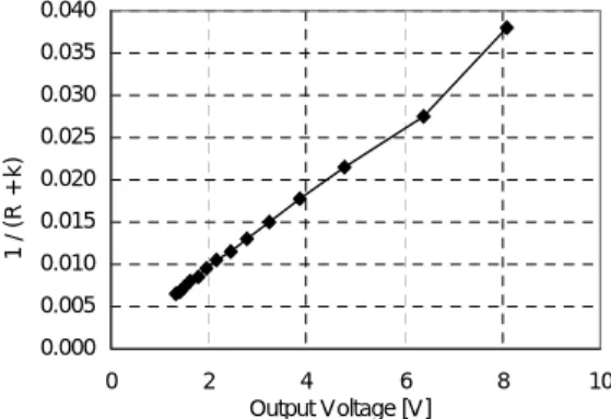
The analyzed measured data that is at the body 4.2 are linearized with inverse proportion at model(1). Fig.9 indicates the graph for voltage vs. distance that linearized by inverse proportion. Gradient 'm' and 'b' on the intercept 'Y' that is at model(3) can be obtained from the data on the graph. Gradient 'm' is 0.004501 and 'b' on the intercept 'Y' is 0.000521.
0.000 0.005 0.010 0.015 0.020 0.025 0.030 0.035 0.040 0 2 4 6 8 1 Output Voltage [V] 1 / ( R + k ) 0 -60 -40 -20 0 20 40 60 -60 -40 -20 0 20 40 60 X Distance [cm] Y D is tanc e [ c m] .
Fig. 9 Consecutive Scanning Data.
5. CONCLUSION
In this paper, low cost range finder system for intelligent mobile robot is developed. First of all, obtain the distance vs. voltage data from experiment and analyze the non-linear output characteristic with that data. Convert the data with linearizing function. Once more, extract coefficient with linearizing function, and then, calculate correct distance. With this, develop the system that obtain environmental data from 360˚ rotation and scanning. Build environmental map, and compare with real map. As a consequence of experiment, it is clear that this system gives very exact environmental information. Hereafter, this system would be applied to mobile robot to build the environmental map while moving.
Fig. 7 Linearized characteristic curve.
Through the process, 'K' the coefficient error can be determined. But changing the 'K' gives an critical effect to the voltage vs. distance, so the calculated data from linearization must be used as the lowest error 'K'. SSE (SUM of Squared Error) is the most appropriate model for obtaining the 'K', and can be defined as:
∑
∑
= = = 150 20 ) -( d E SSE 실측거리 변환거리 ACKNOWLEDGMENTSThis paper was supported by “Samsung Gwang-ju
electronics”
Fig. 10 shows the value of SSE by substituting from 5 to 8 for K, and 'K' the coeffcient error, so to speak, the average of the lowest error is 6.15.
REFERENCES
[1] H. G. LEE and S. D. Park “Development strategy intelligent robot industry of ministry of commerce industry and energy,” Proceeding Conference of Korea
ICCAS2005 June 2-5, KINTEX, Gyeonggi-Do, Korea
Robotics Society, Robot and Human, pp. 5-14, 2004. [2] S. R. OH “Network based intelligent service robot,”
Proceeding Conference of Korea Robotics Society, Robot and Human, pp. 21-32,2004.
[3] H. Y. Chung and K. C. Park “ Location information system for service robot”, Proceeding Conference of Control, Automation, and Systems Engineering Vol. 8, No. 5, 2002.
[4] I. S. Joung and H. S. Cho “ Two-dimensional depth data measurement using an active omni-directional range sensor,” Journal of Control, Automation and Systems Engineering, Vol, 5, No. 4, May. 1999.
[5] Y. S. Ro “A study on the psd sensor system for localization of mobile robots,” Journal of control, Automation and Systems Engineering, Vol. 2, No. 4, December, 1996.