A CFD Study on Inlet Plenum Flow Field of Pebble Bed Reactor
Min-Hwan Kim, Won-Jae Lee, Jong-Hwa ChangKorea Atomic Energy Research Institute P.O.Box 105, Yuseong, Daejeon, Korea, 305-350
[email protected] 1. Introduction
High temperature gas cooled reactor, largely divided into two types of PBR (Pebble Bed Reactor) and PMR (Prismatic Modular Reactor), has becomes great interest of researchers in connection with the hydrogen production.
KAERI has started a project to develop the gas cooled reactor for the hydrogen production and has been doing in-depth study for selecting the reactor type
between PBR and PMR[1][2]. As a part of the study,
PBMR (Pebble Bed Modular Reactor) was selected as a reference PBR reactor for the CFD analysis and the flow field of its inlet plenum was simulated with computational fluid dynamics program CFX5. Due to asymmetrical arrangement of pipes to the inlet plenum, non-uniform flow distribution has been expected to occur, giving rise to non-uniform power distribution at the core. Flow fields of different arrangement of inlet pipes were also investigated, as one of measures to reduce the non-uniformity.
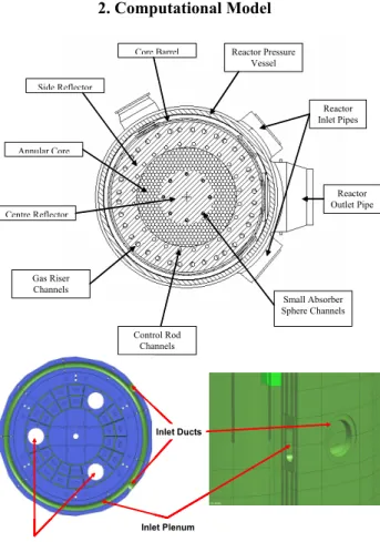
2. Computational Model Reactor Outlet Pipe Reactor Inlet Pipes Reactor Pressure Vessel Core Barrel Side Reflector Annular Core Centre Reflector Gas Riser Channels Control Rod Channels Small Absorber Sphere Channels Inlet ducts Defuel Chutes Inlet plenum Inlet ducts Defuel Chutes Inlet plenum Inlet Ducts Inlet Plenum Defuel Chutes Inlet ducts Defuel Chutes Inlet plenum Inlet ducts Defuel Chutes Inlet plenum Inlet Ducts Inlet Plenum Defuel Chutes
Figure 1. Inlet Plenum configuration of PBMR
Figure 1 shows the configuration of PBMR inlet plenum. In the PBMR design, internal flow paths of reactor are designed to prohibit direct contact of hot gas with reactor pressure vessel using conventional steel.
The flow coming out of two reactor inlet pipes, symmetrically located to reactor outlet pipe, enters inlet plenum which is connected with upper plenum via tens of rising channels.
The numerical model of the inlet plenum was set up based on the following reference dimensions of PBMR.
- Inlet pipe diameter: 0.6m
- Inlet plenum inner diameter: 4.822m - Inlet plenum outer diameter: 5.262m - Inlet plenum width: 0.22m
- Inlet plenum height: 0.6m
- Angle between two inlet pipes: 40o
- Riser channel diameter: 0.17m
As the inlet plenum has a symmetric shape, half of which was selected for the computation. Figure 2 shows the computation model and mesh system for the present study. Inlet Symmetry Riser Outlet 1 2 18 17 Inlet Symmetry Riser Outlet 1 2 18 17
Figure 2. CFD model and mesh system for inlet plenum Inlet velocity is specified for the inlet boundary, calculated from the following inlet conditions.
- Working fluid: Helium at 500℃ and 90 bar - Mass flow rate: 192.7 kg/s
For the outlet boundary, the relative constant static pressure was maintained. The turbulence model was the standard k-ε model with wall-function method. The default turbulence intensity of 5% and auto-computed length scale were selected for the inlet turbulent condition. Except the symmetry, no-slip wall boundary condition was applied.
During the mesh generation, the computational regions were divided into three regions, which are the inlet pipe, the plenum, and the riser channel, respectively. The hexahedral mesh was used for the region of the inlet pipe and the riser channel. Tetrahedral mesh with prism layers was generated for the plenum region.
Transactions of the Korean Nuclear Society Autumn Meeting Busan, Korea, October 27-28, 2005
The three-dimensional Navier-Stokes equations for the inlet plenum were integrated using CFX5 computational fluid dynamics codes.
The purpose of this study is to investigate the non-uniform flow distribution of the Inlet Plenum. But this non-uniformity was already expected from the shape of inlet plenum. So we also investigate an effect of the change of the inlet pipe angle. In addition to the reference configuration, therefore, two options are considered, which are 0 and 180 degree of the angle between the two inlet pipes.
3. Results
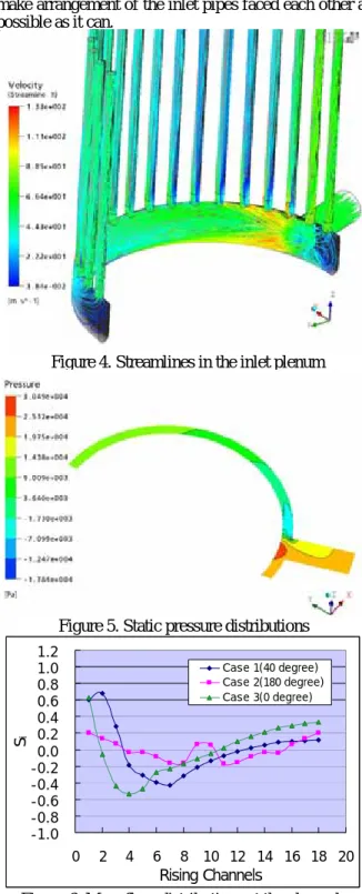
Figure 4 shows the streamlines in the inlet plenum. The flow coming out of the inlet pipe directly impinges on the plenum wall and changes its direction. Much of the flow goes to the larger space of the plenum. Static pressure contours at a mid-plane of the plenum are shown in Figure 5. The pressure near side of the symmetry shows much higher value than the opposite. In this region, the symmetry prevents the inlet flow from expanding and makes the pressure built up. Due to the high pressure, flow rates through the two riser channel connected to this region is much higher than the others.
Figure 6 shows mass flow distributions at the channels. To verify the effect of changing the inlet pipe angle, the results for 0° and 180° are plotted together with the reference case of 40°. The x-axis is assigned number of rising channels, which is from 1 to 18. The y-axis is a normalized mass flow deviation, defined by
avg avg i
i m m m
S = & − & &
In the case of the reference, there is a wide variation in the mass flow rates of rising channels. The high mass flow rate is observed in the stagnant region, channel no. 1 and 2. But the region for the flow expansion side shows rapid decreasing flow rates. This is local pressure decrease which is followed by the rapid turning of the inflow. After that, gradual increase of mass flow is observed with the recovery of pressure. The case 2 shows symmetric flow distributions and the smallest mass flow deviation among the three cases because there is enough space in the plenum to expand the inflow after turning and no local pressure build-up like as the reference. The case 3 shows similar distribution to the reference.
4. Conclusions
The CFD analysis has been conducted to investigate flow distribution in the inlet plenum for the reference PBR. The results allow us to draw the following conclusions.
The inlet plenum flow field shows very complex flow pattern which is impingement, turning, and branch. The reference case gives high non-uniform flow distribution in the rising channels which is about 70% higher and 40% lower mass flow rate when it compared with the average value.
The 180° angle arrangement of the inlet pipes reduce the mass flow deviation to less than 20%. It is beneficial for the uniform core inlet distribution to
make arrangement of the inlet pipes faced each other as possible as it can.
Figure 4. Streamlines in the inlet plenum
Figure 5. Static pressure distributions
-1.0 -0.8 -0.6 -0.4 -0.2 0.0 0.2 0.4 0.6 0.8 1.0 1.2 0 2 4 6 8 10 12 14 16 18 20 Rising Channels Si Case 1(40 degree) Case 2(180 degree) Case 3(0 degree)
Figure 6. Mass flow distributions at the channels
Acknowledgement
This study has been carried out under the Nuclear R&D Program by MOST.
REFERENCES
[1] C. H. Kim et al, Preliminary Study on Coupling High Temperature Gas Cooled Reactor with Hydrogen Production System, Proceedings of the Korean Nuclear Society Fall Meeting, 2004.
[ 2] Y. J. Lee et al, Preliminary Study on the NHDD Plant Configurations, a VHTR coupled to Hydrogen Productions systems, Proceedings of ICAPP, 2005