Th.1.A.1.pdf ECOC Technical Digest © 2012 OSA
Theories and Applications of Chromatic Dispersion Penalty
Mitigation in All Optical OFDM Transmission System
Invited Paper
Malaz Kserawi(1), Satoshi Shimizu(2), Naoya Wada(2), Ahmed Galib Reza(1), and June-Koo K. Rhee(1)* (1)
Dept. of Electrical Engineering, KAIST, 291 Daehak-ro, Yuseong-gu, Daejeon 305-701, S. Korea, *[email protected]
(2)
National Institute of Information and Communications Technology, 4-2-1, Nukui-Kitamachi, Koganei, Tokyo, Japan
Abstract Fiber chromatic dispersion in optical OFDM transmission degrades carrier orthogonality,
resulting in system penalty. Such penalty can be mitigated by per-carrier delay precompensation and spectrum filtering. Theoretical and experimental results show both methods restore performance without overhead or guard interval.
Introduction
All optical OFDM (AO-OFDM) is gaining more attention recently due to its ability to transfer data over 100 Gbps in a single wavelength channel with high spectral efficiency. Such high transmission speeds can be achieved after substituting the electrical processors of transceivers such as the discrete Fourier transform (DFT) circuit with optical parallels. Previous works suggested fabricating optical DFT circuit using phase shifters and couplers1, delay interferometers and optical gates2, or arrayed waveguide gratings (AWG) utilizing slab-star couplers3.
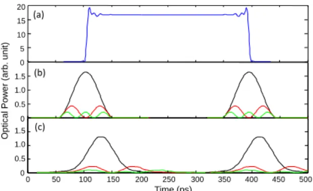
Applying the aforementioned methods to achieve high data rates imposes a challenge in maintaining orthogonality between OFDM carriers because orthogonal demultiplexing of tightly-packed narrow-band carriers by DFT makes the system more sensitive to chromatic dispersion (CD). The penalty of dispersion consists of two parts. The first problem is symbol waveform deformation that causes symbol interference (ISI) and the other is inter-carrier interference (ICI). The latter is inherently canceled by DFT at designated temporal sampling points with no CD (Fig.1b). As CD is
introduced, the ICI cancellation becomes imperfect and minimum positions of ICI shift in time (Fig. 1c) due to the group delay difference between different carriers, degrading carrier-carrier orthogonality. Fig. 1 is an example of 3-carrier transmission.
Dispersion penalty mitigation in AO-OFDM was investigated in the literature4-7. The proposals considered the addition of guard band interval, using cyclic prefix, or sub-rate data modulation of carriers. Such methods can avoid dispersion penalty but sacrifice a large portion of the spectral efficiency and reduce the feasible data rates.
In this paper, we propose theoretical and numerical understandings of CD penalty mitigation techniques and experimentally demonstrate two techniques to overcome the dispersion penalty. The first technique is the time-delay precompensation. As shown in Fig. 2,addition of per-channel tunable delay lines at the transmitter side allows control of arrival times of all carriers at the receiver so that all symbols arrives at the same time to maintain the orthogonality of the OFDM carriers at designated data sampling points in the time domain. The second technique is narrow-band filtering at all carriers on the transmitter side so that side-lobe frequency components of a certain channel are removed completely. The benefits of channel filtering can be looked at as follows:
Even though a spectral side lobe of a transmitted carrier experiences the same
Fig. 2: Addition of narrow-band filters and tunable delay lines in order to eliminate and align interference null position.
IDFT DFT Tx Rx Ch1 Ch2 Ch3 ICI
Fig. 1: Symbol pattern for carriers 2, 3, and 4 (a), and the corresponding ICI into carrier 1 from carriers 2 (black),3 (red), and 4 (green) in case of B2B (b) and of 20km SMF-28 transmission fiber (c). The symbol period is 100 ps. 0 0 50 100 150 200 250 300 350 400 450 500 0 0.5 1.0 1.5 (b) (c) 0 0.5 1.0 1.5 Time (ps) Opt ic al Pow er (arb . unit ) (a) 5 10 15 20
Th.1.A.1.pdf ECOC Technical Digest © 2012 OSA
group delays as other carrier at the same frequency, the interference null point shifts with the transmitted carrier.
ICI waveform broadening produces residual power at null points resulting in interference even if a temporal orthogonal point is aligned.
Channel filtering is an effective alternative to precompensation since complete elimination of interference is better than null point alignment. However, filtering is not fully effective on adjacent channel ICI because of the frequency overlap.
Experiment setup
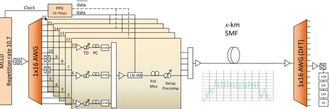
The experimental setup of our design is shown in Fig. 3. A comb consisting of 15 tones is generated using mode-locked laser diode (MLLD) and a filter at a repetition rate of 10.7 GHz. The comb is fed into a 1x16 AWG device to generate 15 continuous-wave carriers separated exactly by 10.7 GHz. Fig. 4 shows a measured typical transfer function of a carrier port of the AWG sample taken from the port for carrier 8 overlapped on ideal transfer functions of all 15 carriers used in the experiment. The figure exhibits the AWG device performance limit with the current device technology. The outputs of the AWG are separated into 5 groups in order to:
Apply and ̅̅̅̅̅̅ of pseudorandom bit
sequence on interleaving channels
alternatively to decorrelate adjacent carriers.
Apply a polarization of 0° and 90° on interleaving channels to reduce adjacent channel crosstalk by polarization multiplexing for this proof of concept experiment.
Control the precompensation alignment of only 4 adjacent neighbors at a time since adjacent neighbors impose higher interference than far channels which can be neglected.
Each group consists of 3 carriers with a frequency step of 5x10.7GHz with consistent power and polarization. The 3 carriers in the
same group are modulated, polarization controlled, and delay-adjusted for pre-compensation together. In our experimental setup, we characterized performance of carrier 8 for application of both delay precompensation and carrier narrow-band filtering, by applying filtering on its adjacent channels Ch7 and Ch9. The 5-carrier-groups are coupled together to form an OFDM symbol centered at a wavelength of 1549.8nm which spectrum is shown in the inset of Fig. 3. The OFDM symbols are then transmitted through a transmission system with a fiber length of 0km, 54km, 75km, and 83km. The used fiber is a Single Mode Fiber (SMF-28) with a dispersion coefficient of 16 ps/nm/km. At the receiver side, symbols are demultiplexed using a 16x1 AWG. We then measure the BER of carrier 8 from the AWG output with an O/E converter, clock data recovery, and bit error detector.
Experimental results
We first investigate the effect of delay precompensation with fiber lengths of 0km, 54km, 75km, and 83km. The the corresponding group delays between adjacent carriers are measured to be approximately 0ps, 55ps, 80ps, and 90ps, respectively. These group delay
Fig. 4: Filter function of the AWG at port number 8 with corresponding location of channels.
Fig. 3: Experimental setup.The inset shows the OFDM symbol spectrum of 15x10.7 GHz carriers
M LL D R ep et it io n ra te 10 .7 1 x1 6 A W G 1 x1 6 A W G (D FT ) 2 3 4 5 7 8 9 10 12 13 14 15 16 x-km SMF VOA O/E CDR ED Delay Precomp. TD PC VOA VOA VOA Pol. Mux LN-IM PPG 10.7Gbps 1 6 11 data ____ data Clock
Th.1.A.1.pdf ECOC Technical Digest © 2012 OSA
contribute in a significant increase of BER due to the orthogonality degradation. After applying delay pre-compensation with the same aforementioned group delay values and restoring the ICI null position alignment, the BER is reduced with approximately an order of magnitude. Fig. 5 shows the measured BER values of carrier 8 with and without precompensation measured at a received optical power of -6 dBm. The corresponding eye diagrams for the case of 54km is shown in Fig. 6, which clearly show how effectively the ICI is reduced and signal quality is improved by simply adjusting delays.
Ideally-matched filtering should be able to remove all interferences from neighbors, and in this case, delay precompensation is not needed. This is not practically achievable with simple filtering functions. However, filtering of ICI to second and farther neighbor carriers can be achieved effectively, hence to enhance mitigate the system penalty due to not only CD but also other impairment such as polarization mode dispersion and multipath interference that can break the OFDM orthogonality.
Filtering can be implemented in parallel with delay precompensation for additional improvement. Our observation from the experiment shows that lowering the effect of adjacent channels is far more important than removing interference of channels that are far in
the spectrum; therefore, we installed the filters on carriers 7 and 9 for our measurements. Fig. 7 shows the results of filtering only and filtering with delay precompensation. The results clearly show that filtering successfully reduces a large portion of the BER. As delay precompensation added, the majority of the dispersion penalty is mitigated. Both techniques do not require any overhead or waste of the spectrum usage where 160.5 Gbps is transmitted over 160.5 GHz. Considering 7% FEC overhead, the achieved spectral efficiency is approximately 0.93bit/s/Hz.
Conclusion
We investigated an AO-OFDM technique with two dispersion mitigation techniques: delay precompensation and channel filtering. Experimental results show that applying both techniques can reduce a large portion of the system penalty due to chromatic dispersion with no additional overhead. A total of 160.5 Gbps transmission is successfully achieved with 0.93bit/s/Hz spectral efficiency with an 83-km fiber dispersion tolerance in an SMF-28 transmission system.
Acknowledgments
This work at KAIST was supported in part by the IT R&D program of MKE/IITA [2008-F017-02, 100Gbps Ethernet and optical transmission technology development].
References
[1] K. Lee et al., Opt. Exp. 16, pp. 4023, (2008). [2] A. Sano et al., ECOC, Paper PDS1.7 (2007). [3] K. Takiguchi et al., Opt. Lett. 36, 1140 (2011). [4] D. Hillerkuss et al., Nature Photon., 5, 364
(2011).
[5] S. Yamamoto et al., JLT. 28, 157, (2010). [6] I. Kang et al., ECOC, Paper Th.11.B (2011). [7] Z. Wang et al., Opt. Exp. 19, 4501 (2011).
Fig. 5: BER of carrier 8 with and without precompensation on a fiber transmission system.
FEC level
Fig. 6: Eye diagrams of an OFDM demultiplex output at carrier 8 before precompensation (a) and after precompensation (b) .
(a) (b)
Fig. 7: BER of Ch8 in cases of back-to-back, 54km SMF, 54km with channel filtering, 54km with channel filtering and delay precompensation.
B 2B 54 km 54 km + Fi lt er in g 54 km + F ilt er in g + Pr ec om pe ns at io n