Journal of Mechanical Science and Technology 34 (10) 2020
Original ArticleDOI 10.1007/s12206-020-0911-z
Keywords:
· Double compression ramp · Bluntness leading edge · Supersonic flow · Flow visualization · Wind tunnel experiment
Correspondence to:
Ikhyun Kim [email protected]
Citation:
Kim, I., Park, G., Byun, Y. H. (2020). Experimental investigation of the effects of leading edge bluntness on supersonic flow over a double compression ramp. Journal of Mechanical Science and Technology 34 (10) (2020) 4193~4199. http://doi.org/10.1007/s12206-020-0911-z Received May 4th, 2020 Revised August 7th, 2020 Accepted August 10th, 2020 † Recommended by Editor Yang Na
Experimental investigation of the effects
of leading edge bluntness on supersonic
flow over a double compression ramp
Ikhyun Kim1,2, Gisu Park1 and Yung Hwan Byun3
1Department of Aerospace Engineering, KAIST, Daejeon 305-701, Korea, 2Department of Engineering
Science, The Southwell Building, University of Oxford, Oxford OX2 0ES, United Kingdom, 3Department of
Aerospace Engineering, Konkuk University, Seoul 14370, Korea
Abstract
Understanding the flow characteristics over a double compression ramp is crucial for high-speed vehicle design. Leading edge bluntness is a key factor influencing the formation of a separation region on a double compression ramp flow. In the present study, the effect of bluntness on a double compression ramp is investigated experimentally at a nominal Mach number of 4. The test model has 13º and 40º inclinations with respect to the freestream. Five different levels of leading-edge radius, varying from 0.0 to 2.0 mm, were subjected to supersonic wind tunnel tests. Shadowgraph and infrared thermography techniques were employed to visualize the flow features of the double ramp model. Measurements of surface heat-transfer along the centerline of the test model were obtained from the acquired infrared images. It is shown that the leading-edge radius alters the separation characteristics as well as the surface heat-transfer. Possible reasons for such flow characteristics are discussed.1. Introduction
The compression ramp, one of the most fundamental geometries, is considered in the design of high-speed vehicles. It is known that the flow field of a compression surface is dominated by shock wave/boundary layer interactions that induce extended separations and cause boundary layer instability, and high thermal pressure loads on the surface [1-3]. During supersonic flights, such interactions are likely to be important factors that affect the vehicle performance. Hence, control mechanisms for this flow feature have been the subject of many investigations.
Some studies have reported mechanisms for controlling the separation size of the compres-sion ramp. Understanding the separation characteristics induced by shock wave/boundary layer interactions is crucial for high-speed vehicle engineering and implementation. Among various techniques for controlling separation, blunting the leading edge has been the most widely considered [4, 5].
In the early works of Holden [6, 7], it was revealed that the separation zone first grows until it reaches the critical radius of the leading edge; the separation zone then decreases with further increase of radius at hypersonic Mach number. Many subsequent works focused on links be-tween separation zone size and leading-edge bluntness. Coet and Chanetz [8] performed pressure and heat-transfer measurements of Mach 10 flow using a single compression ramp model and observed that separation zone size was reduced due to the favorable pressure gra-dient induced by the presence of bluntness. Neuenhahn and Olivier [9] demonstrated Mach 8 flow over a double compression ramp and observed that leading edge bluntness leads to in-creasing bow shock curvature in the vicinity of the leading edge, thereby altering the separation length. Subsequent works evaluated the boundary layer thickness, sonic height, entropy layer, and pressure differences; effects of bluntness in hypersonic flows were numerically investi-gated [4, 5, 10]. Recently, the effects of chemical reactions and leading-edge bluntness on shock wave/boundary layer interactions were investigated by Desai et al. [11] at a Mach num-ber of 6 with an in-house computational fluid dynamics solver. As described above, most find-
© The Korean Society of Mechanical Engineers and Springer-Verlag GmbH Germany, part of Springer Nature 2020
ings have been restricted to a single compression ramp at high Mach number. Thus, it is essential to understand flow charac-teristics of a practical configuration, such as a double compres-sion ramp, at relatively low Mach number. The double com-pression ramp usually represents realistic geometrical compo-nents of high-speed vehicles, such as engine inlets, wing body junctions, and control surfaces [12-15].
The main objective of this work is to understand, via experi-mental investigation, the effect of bluntness on the flow charac-teristics over a double compression ramp. The experiments were conducted in a supersonic wind tunnel at a freestream Mach number of 4. The feasibility of visualizing the supersonic flow over the double compression ramp by shadowgraph and infrared (IR) thermography techniques was established in prin-ciple in our recent work [16-19]. Typical flow features such as occurrence of separation shock, separation region, and reat-tachment shock over the investigated geometry are reported in our previous studies (see Fig. 1) [16, 17]. In view of the present research aim, double compression ramp geometries with vari-able degrees of leading-edge bluntness were employed. Shadowgraph visualization, together with the IR thermograph technique, is currently used to investigate the major flow fea-tures in the test model.
2. Experimental apparatus
2.1 Supersonic wind tunnel
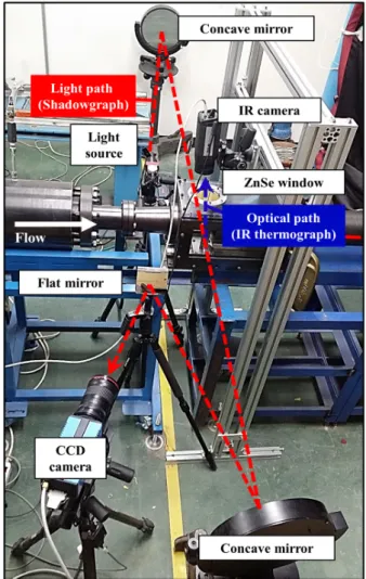
The experiments were carried out at Konkuk University’s su-personic wind tunnel, called the model aerodynamics facility (MAF), as shown in Fig. 2. The facility was originally designed and built by the Institute of Theoretical and Applied Mechanics (ITAM) of the Russian Academy of Sciences. Information on the design, geometric structure, and experimental calibration of the tunnel can be found in Ref. [20]. The tunnel is a blow-down type facility that can produce Mach flow numbers from 2 to 7. The entire system contains high-pressure vessels, an axisym-metric nozzle, a working section, and a diffuser. The diffuser enables decreasing of the pressure inside the closed test sec-tion during runs below 0.01 MPa; system produces supersonic flow at the nozzle without any vacuum chamber [20]. The test
section is of free-jet type with dimensions of 320 mm (length) x 226 mm (height) x 200 mm (width), having three windows that provide optical access from the sides and from above. In this study, a 100 mm diameter Mach 4 axisymmetric nozzle is em-ployed. Dry air is used as the working fluid. Tests were
con-ducted at a plenum total temperature T0 of 290 K, freestream
pressure P∞ of 14 kPa, and freestream Mach number M∞ of 4.0;
corresponding Reynolds number Re∞ based on the test model
height was approximately 4.7 x 10⁶, as can be seen in Table 1.
The MAF run time was about 1 s. Calibration experiments were conducted previously and the reliability of supersonic flow
for-Table 1. Test flow conditions [16-18]. Test conditions M∞ (-) 4 T0 (K) 295 P∞ (kPa) 14 T∞ (K) 70 u∞ (m/s) 673 Re∞ (-) 4.7 x 10⁶
Fig. 1. Schematic of double compression ramp flow [16, 17].
mation has been demonstrated by various studies, details of which can be found in Refs. [16-23].
2.2 Test model
Fig. 3 shows the test model installed in the test section. The test model is 45 mm wide and 22 mm high. The double com-pression ramp surfaces have 13º and 40º deflection angles for the first and second ramps, respectively, with respect to the freestream direction. The test model was fabricated from a poly-methyl-methacrylate (PMMA) material, the least conduc-tive material possible, chosen in order to maximize the surface temperature increase for any given test conditions, and satisfy-ing the requirements of the IR thermography technique [17, 24].
Leading edge radius Rn was varied from 0.0 to 2.0 mm.
2.3 Optical diagnostics
Two flow visualization techniques were employed at two dif-ferent planes. Fig. 4 shows the optical arrangement for the shadowgraph and Infrared (IR) thermography techniques. Full details regarding the optical setup for both visualization tech-niques are given in our previous works [16-19], so only a brief description is included here. To capture the instantaneous supersonic flow field, a shadowgraph system was implemented consisting of two concave mirrors and standard shadowgraph optics. The red dotted line in the figure represents the light path for the shadowgraph system. An 80 W capacity LED lamp light source was used for the high-speed camera to capture the flow
features. A PCO© 1600 high-speed camera recorded the
im-ages with an exposure time of 100 us. Imim-ages were obtained at a sampling rate of 32 kHz and a resolution of 1600 x 1200 pixels.
The transient surface temperature of the test model was
re-corded by an FLIR© A655SC Infrared (IR) thermal imaging
camera, which has an operational spectral band of 7.5–14.0 μm. The blue dotted line in the figure denotes the optical path of the IR camera. This camera operates in a standard tempera-ture range of 233 to 423 K, with a reported reading accuracy of ±2 K. The noise equivalent temperature difference for this
de-vice is reported at less than 30 mK [25]. Two-dimensional tem-perature distribution was obtained from IR images taken at a resolution of 640 x 480 pixels and a scanning rate of 50 frames per second. The IR camera was positioned vertically above the test model and fitted with a zinc selenide (ZnSe) window that provides optical access in the corresponding IR wavelength range. At the beginning of the experiments, blackbody-based
calibration was performed using an FLIR© Commercial
Sys-tems Device from the Producers Company, with the help of
Eurotherm© temperature traceable equipment [18, 19]. This
calibration procedure characterized the IR camera detector’s response to a series of known blackbody temperatures. The uncertainty associated with the temperature measurement was found to be ±1 K.
At the same time, to guarantee good surface temperature measurements by the IR system, in-situ calibration was per-formed with a high-accuracy K-type thermocouple taped to the test model. Results agreed with each other with an uncertainty of less than ±0.5 K [18]. The resulting thermal images were
processed and analyzed using the FLIR© IR V3.3 professional
commercial software. The emissivity value of the test model was set at 0.85, known to be the emissivity value of the PMMA
Fig. 3. Test model in test section.
material. The transient temperatures from the thermal images were used to evaluate the heat flux distribution, which is gen-erally applied for the study of flow separation and transition behavior [24-27]. The well-known semi-infinite one-dimensional heat conduction equation proposed by Schultz and Jones [28] was used to determine heat flux q, expressed as,
0.5 1 0.5 0.5 0.5 1 1 2( ) ( ) ( ) ( ) ( ) n p i i i n i n i c T t T t q t t t t ρ κ π = − − − = − + −
∑
(1)where ρ, cp, and κ are the density, specific heat capacity, and
thermal conductivity of the test model material (ρ = 1180 kg /m3,
cp = 1470 J/(kg·K), and κ = 0.2 W/(m·K) for the PMMA [12, 15]).
This numerical expression describes the surface heat-transfer
at time ti as a function of the wall temperature T(ti), which is
commonly used in short-duration impulse facilities [26-31].
3. Results and discussion
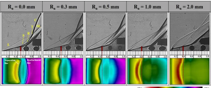
The shadowgraph images in Table 2 show the changes in the flow pattern for the double compression ramp as the blunt-ness radius is varied from 0.0 to 2.0 mm. Corresponding IR images of the test model surface are included at the bottom of each subfigure. The flow direction is left to right. Because of the relatively cool freestream flow, the IR overall images indi-cate temperatures below room temperature. The leading-edge shock (L), separation shock (S), and reattachment shock (R) are clearly visualized in the shadowgraph images. Leading edge shock (L) is formed when supersonic flow encounters the first ramp and a boundary layer develops. However, the pre-sent visualization data cannot provide sufficient information to distinguish the boundary layer as turbulent or laminar. In gen-eral, the boundary layer flow over the ramp surface will experi-ence laminar-transition-turbulent processes. In case of no de-tached shock wave ahead of the leading edge, the boundary layer flow can be analyzed in terms of Reynolds number, but
due to the presence of the bow shock wave ahead of the ramp, the flow will be vortical and unsteady as well. Thus theoretical approaches to predict the boundary layer flows may be bearing unreasonable results. The present measurement is not enough to give some information on the boundary layer flow.
Separation shock (S) takes place in front of the separation region and the flow reattaches, generating reattachment shock (R). Strong interaction between the shock wave and the boundary layer can be seen near the flow reattachment region. These shock interactions form a triple (T) point between the slip line (SL) and the combined shock (C). At the location of the separation shock, it can be seen in the IR images that the measured temperature is relatively lower; this is due to the effect of shock-induced flow separation and this has been re-ported by many previous studies, which show similar trend with the present results [13-15]. IR images show that the lowest surface temperature is along the second ramp because the flow in this region has gone through two shock waves, the ini-tial leading-edge shock and then the reattachment shock [13]. Near the end of the first ramp region, because of flow spillage due to the finite span of the test model, the IR images show spanwise features from the central region toward the separa-tion line and toward the side edges. In this experimental ar-rangement, there will be unintended three-dimensional flow due to the finite test model and test section size; this has often been an issue of interest. Similar observations regarding the spanwise features of the separation region have been reported by researchers using other experimental techniques such as pressure sensitive paint measurement and oil-flow visualization [13-15]. Recently, numerical analysis by Lee et al. [22] showed that the separation region becomes narrow toward the side edges due to the streamlines near the outer side of the edge passage.
As shown in Table 2, although it can be difficult to see, the separation shock front (denoted by the red arrow) moves up-stream along the first ramp as the leading-edge radius
creases from 0.0 to 1.0 mm. This movement indicates that increased bluntness results in widening of the size of the sepa-ration region. Further increases in the bluntness apparently do not affect the separation shock position. This is possibly thought to be due to the relative thickness of the boundary layer and the entropy layer, which is inevitable in highly blunted configurations [4]. As noted by John and Kulkarni [4], the change in entropy layer thickness may alter the flow properties both at the edge and within the boundary layer, which can af-fect the trend of changes of separation region. Additionally, it can be seen that the location of the triple point shifts down-stream as the bluntness increases. A similar observation can be found in the computational analysis by John and Kulkarni [10]. It is noted that the bluntness increases the magnitude of the favorable pressure gradient, which accelerates the flow behind the leading-edge shock and induces velocity distribution on the boundary layer as it approaches the surface. Conse-quently, the flow environment affects the separation shock location, separation zone size, reattachment shock location, and triple point location with respect to the corresponding posi-tion in the sharp leading-edge case.
In regard to the case of Rn = 2.0 mm, it can be seen that
shadowgraph and IR images show somewhat different flow
patterns. With Rn = 2.0 mm, although the bluntness increased,
the separation region narrowed its size. This may be due to the different leading-edge shocks formed at the leading edge. Fig. 5 provides an optically zoomed shadowgraph image of the
leading-edge region for the case of Rn = 2.0 mm. It can be
seen that detached curve shock formed at the leading edge. It is evident in the computational analysis findings that the strong detached shock alters the flow properties when flow velocity decreases while temperature and pressure increase in the shock layer [8-10]. These changes might affect the flow fea-tures downstream, as can be seen in the figure.
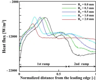
Fig. 6 shows the heat flux distributions along the test model centerline, obtained from IR images, averaged over the steady test time period. The heat fluxes are taken to be negative
be-cause they are directed from the test model to the flow. For Rn
= 0.0 to 1.0 mm, the absolute heat transfer is at a minimum on the first ramp, as is commonly observed at the start of the separation zone [14, 32, 33]. This location moves upstream with increases in the leading-edge bluntness. Immediately, downstream of the separation region, due to a boundary layer reattachment, there is a gradual increase in the absolute mag-nitude of the heat transfer [33]. A decrease in the absolute magnitude of the heat transfer on the second ramp is observed
with increase in the leading-edge radius. The case of Rn = 2.0
mm, which showed detached bow shock at the leading edge (see Fig. 5), however, apparently has different heat flux distri-butions. According to John et al. [5] the presence of detached bow shock creates an entropy gradient normal to the flow of the leading edge. Based on their computational analysis, they stated that this entropy gradient induces a strong vorticity out-side the boundary layer and provides a stabilizing effect, reduc-ing the intensity of shock wave/boundary layer interactions.
As expected from the Crocco’s theorem, the strong rotating flow is initiated downstream of the curved shock wave, which will cause the vorticity and entropy production as well, and influence the heat transfer on the ramp surface. In particular, with an increase in the bluntness, the flow unsteadiness due to shock oscillations will be appearing more significant. Unfortu-nately we cannot make clear such complicated flow features from the present experimental data and will be investigating those flows using three-dimensional CFD study in the subse-quent work of the present study.
4. Conclusions
The effect of leading edge bluntness on a double compres-sion ramp has been experimentally investigated in a super-sonic wind tunnel. To understand the flow characteristics, the shadowgraph capturing method, along with infrared thermo-graphy techniques, was employed. Flow features including separation shock, separation region, and reattachment shock were clearly visualized. It was noticed that even a small level of leading-edge bluntness can alter the flow pattern significantly. Specifically, it has been shown that the start position of the separation zone shifts upstream as the level of leading-edge bluntness increases to 1.0 mm. However, further increases in
Fig. 5. Optically zoomed shadowgraph image for Rn = 2.0 mm leading
edge.
bluntness have been found not to significantly affect the corre-sponding location and led to very few changes in the flow fea-tures. From the IR images, spanwise features due to the three-dimensional flow effect in the vicinity of the separation zone were clearly discernible, something which cannot be captured using the standard shadowgraph technique. Flow spillage through the edge side of the finite span was believed to be responsible for these features. Based on the ranges of vari-ables in the present experiments, the increased leading blunt-ness can be applied to mitigate aerodynamic heating in the vicinity of the second ramp of the realistic high-speed vehicle. The results of the current observations may provide insight into the effects of the bluntness on the flow behavior on a double compression ramp; the authors believe that this study can help in validation and parametric studies for the high-speed vehicle design community.
Acknowledgments
This work was supported by Defense Acquisition Program Administration and Agency for Defense Development (No. UD130042CD). This work was carried out in the Department of Aerospace Engineering at Konkuk University. The authors would like to thank Mr. Jaeho Lee and Dr. Sungmin Lee for their technical help in operating the supersonic wind tunnel.
References
[1] J. D. Anderson Jr., Hypersonic and High Temperature Gas
Dynamics, 2nd Ed., McGraw-Hill, New York, USA (1989)
395-406.
[2] D. Dolling, Fifty years of shock-wave/boundary-layer interaction research: What next?, AIAA Journal, 39 (8) (2001) 1517-1531. [3] D. Gaitonde, Progress in shock wave/boundary layer
interac-tions, Progress in Aerospace Science, 72 (2015) 80-99. [4] B. John and V. Kulkarni, Effect of leading edge bluntness on
the interaction of ramp induced shock wave with laminar boundary layer at hypersonic speed, Computer & Fluids, 96 (2014) 177-190.
[5] B. John, V. Kulkarni and G. Natarajan, Shock wave boundary layer interactions in hypersonic flow, International Journal of
Heat and Mass Transfer, 70 (2014) 81-90.
[6] M. S. Holden, Boundary-layer displacement and leading edge bluntness effects on attached and separated laminar boundary layers in a compression corner. PartⅠ: Theoretical study,
AIAA Journal, 8 (12) (1970) 2179-2188.
[7] M. S. Holden, Boundary-layer displacement and leading edge bluntness effects on attached and separated laminar boundary layers in a compression corner. PartⅡ: Experimental study,
AIAA Journal, 9 (1) (1971) 84-93.
[8] M. Coet and B. Chanetz, Experiments on Shock
Wave/bound-ary Layer Interactions in Hypersonic Flow, English Ed, Rech
Aerosp. (1993) 61-74.
[9] T. Neuenhahn and H. Olivier, Influence of the wall temperature and the entropy layer effects on double wedge shock boundary
layer interactions, AIAA Paper 2006-8136 (2006).
[10] B. John and V. Kulkarni, Alterations in critical radii of blunt-ness of shock wave boundary layer interaction, Journal of
Aerospace Engineering, 30 (5) (2017) 04017022.
[11] S. Desai, S. Brahmachary, H. Gadgil and V. Kulkarni, Probing real gas and leading-edge bluntness effects on shock wave boundary-layer interaction at hypersonic speeds, Journal of
Aerospace Engineering, 32 (6) (2019) 04019089.
[12] F. F. J. Schrijer, F. Scarano and B. W. V. Oudheusden, Appli-cation of PIV in a Mach 7 double-ramp flow, Experiments in
Fluids, 41 (2) (2006) 353-363.
[13] L. Yang, H. Zare-Behtash, E. Erderm and K. Kontis, Applica-tion of AA-PSP to hypersonic flows: the double ramp model,
Sensors and Actuators B: Chemical, 161 (1) (2012) 100-107.
[14] L. Yang, H. Zare-Behtash, E. Erdem and K. Kontis, Investiga-tion of the double ramp in hypersonic flow using luminescent measurement systems, Experimental Thermal and Fluid
Sci-ence, 40 (2012) 50-56.
[15] H. Zare-Behtash, K. H. Lo, L. Yang and K. Kontis, Pressure sensitive paint measurements at high Mach number, Flow
Measurement and Instrumentation, 52 (2016) 10-16.
[16] I. Kim, G. Park, Y. Byun and J. Lee, Experimental study of supersonic flows around a double compression ramp with a sidewall, Proc. of KSAS Fall Conference (2015) 55-58. [17] I. Kim, J. Lee, G. Park, Y. Byun and J. Lee, Test research
using an IR thermography technique in a supersonic wind tun-nel, Journal of the Korean Society for Aeronautical & Space
Sciences, 44 (2) (2016) 99-107.
[18] I. Kim, Bluntness effect of double compression ramp in super-sonic flow, Master’s Thesis, Korea Advanced Institute of Sci-ence and Technology, Daejeon, Korea (2016).
[19] S. Lee, I. Kim, J. Lee, Y. Byun and G. Park, Distortion correc-tion of surface temperature measurement using an infrared camera, Journal of the Korean Society for Aeronautical &
Space Sciences, 44 (7) (2016) 545-551.
[20] I. Turko and M. Timofeev, Model aerodynamic facility, Proc. of
KORUS in 7th Korea-Russia International Symposium on
Sci-ence and Technology, IEEE Cat. No.03EX737, 1 (2003)
346-350.
[21] W. Choi, D. Seo, J. Lee and Y. Byun, Modification and per-formance test for improving ability of supersonic/hypersonic wind tunnel (MAF), Proc. of KSPE Fall Conference (2010) 717-722.
[22] H. S. Lee, J. H. Lee, G. Park, S. H. Park and Y. H. Byun, Three-dimensional supersonic flow around double compres-sion ramp with finite span, Shock Waves, 27 (1) (2017) 69-77. [23] H. Lee, Y. J. Kim, Y. H. Byun and S. H. Park, Mach 3
bound-ary layer measurement over a flat plate using the PIV and IR thermography technique, AIAA Paper 2017-0523 (2017). [24] F. F. J. Schrijer, Experimental investigation of re-entry
aero-dynamic phenomena, Ph.D. Thesis, Delft University of Tech-nology, The Netherlands (2010).
[25] L. A. Joseph, A. Borgoltz and W. Devenport, Infrared thermo-graphy for detection of laminar-turbulent transition in low-speed wind tunnel testing, Experiments in Fluids, 57 (5) (2016) 77.
[26] H. Ozawa, S. J. Laurence, J. M. Schramm, A. Wagner and K. Hannemann, Fast-response temperature-sensitive-paint mea-surements on a hypersonic transition cone, Experiments in
Fluids, 56 (1) (2015) 1853.
[27] S. J. Laurence, H. Ozawa, J. M. Schramm, C. S. Butler and K. Hannemann, Heat-flux measurements on a hypersonic inlet ramp using fast-response temperature-sensitive paint,
Experi-ments in Fluids, 60 (4) (2019) 1-16.
[28] D. L. Shultz and T. V. Jones, Heat-transfer Measurements in
Short-duration Hypersonic Facilities, AGARDograph-165, North
Atlantic Treaty Organization, Advisory Group for Aerospace Research and Development (1973).
[29] I. Kim, S. Lee, G. Park and J. K. Lee, Overview of flow diag-nosis in a shock tunnel, International Journal of Aeronautical
and Space Science, 18 (3) (2017) 425-435.
[30] I. Kim, G. Park and J. J. Na, Experimental study of surface roughness effect on oxygen catalytic recombination,
Interna-tional Journal of Heat and Mass Transfer, 138 (2019) 916-922.
[31] I. Kim, S. Lee, G. Park and J. G. Kim, Analysis of nitrogen recombination activity on silicon dioxide with stagnation heat-transfer, Acta Astronautica, 177 (2020) 386-397.
[32] H. C. Shi, J. H. Sa, S, H. Park and Y. H. Byun, Transitional flow analysis over double compression ramp with nose blunt-ness in supersonic flow, Journal of Computational Fluids
Engi-neering, 20 (4) (2015) 36-43.
[33] F. Schrijer, Investigation of Görtler vortices in a hypersonic double compression ramp flow by means of infrared thermo-graphy, Quantitative InfraRed Thermography Journal, 7 (2) (2010) 201-215.
Ikhyun Kim received his Ph.D. degree in
2019 from KAIST. He is currently a Visit-ing Scholar in the Hypersonic Research Group at Oxford Thermofluids Institute. His research interests include high-speed aerothermodynamics and hyper-sonic gas-surface interaction.
Gisu Park received his Ph.D. degree in
2010 from the University of New South Wales. He is currently an Associate Pro-fessor in the Department of Aerospace Engineering at KAIST. His research in-terests include hypersonic flows and high-speed ground-tests.
Young Hwan Byun received his Ph.D.
degree from the University of Maryland in 1988. He is currently a Professor in the Department of Aerospace Engineer-ing at Konkuk University. His research interests include high-speed ground-tests and shock wave dynamics.
![Fig. 1. Schematic of double compression ramp flow [16, 17].](https://thumb-ap.123doks.com/thumbv2/123dokinfo/5093046.77273/2.892.112.766.854.1055/fig-schematic-double-compression-ramp-flow.webp)