Microstructured Ceramic-Coated Carbon Nanotube Surfaces for
High Heat Flux Pool Boiling
Hangbo Zhao,
†Susmita Dash,
†,‡Navdeep Singh Dhillon,
†Sanha Kim,
†Bethany Lettiere,
†Kripa K. Varanasi,
†and A. John Hart
*
,††Department of Mechanical Engineering and Laboratory for Manufacturing and Productivity, Massachusetts Institute of
Technology, 77 Massachusetts Avenue, Cambridge, Massachusetts 02139, United States
‡Department of Mechanical Engineering, Indian Institute of Science, Bangalore 560012, India
*
S Supporting InformationABSTRACT: Stable surfaces with high boiling heatflux are critical to many thermal and energy conversion systems, and it is well-known that the microscale texture and wettability of a surface influences its critical heat flux (CHF). We investigate pool boiling on microstructured ceramic-coated carbon nanotube (CNT) surfaces. CNT microstructures are patterned with precise dimensions over large areas, and a ceramic coating by atomic layer deposition (ALD) imparts stability in the presence of capillary forces and thermal stresses that occur during boiling, achieving a measured CHF as high as 245 W cm−2. We also show that the nanoporosity of the ceramic−CNT microstructures has a negligible influence on the CHF because surface rewetting is dominated by
microscale imbibition. The high CHF values achieved on our surfaces are attributed to the micropatterning and the nanoscale surface texture of the CNTs, which accelerate liquid imbibition upon bubble departure. Our findings also suggest further enhancements in CHF can be made by optimizing the microstructure pattern and improving its wettability. Therefore, micropatterned ceramic−CNT composites are a potentially attractive substrate for industrial applications of pool boiling. KEYWORDS: carbon nanotubes, microstructures, nanoporous, boiling, surfaces, scalable fabrication
■
INTRODUCTIONBoiling is a highly efficient means of transferring heat due to the large latent heat of vaporization. However, there exists a practical limitation in the maximum heatflux a boiling surface can safely transfer, and this is called the critical heat flux (CHF). Beyond the CHF, a vapor layer forms between the liquid and the heating surface, and a transition from nucleate boiling tofilm boiling occurs. This leads to a drastic increase in the substrate temperature and often causes burnout of the boiling surface, a phenomenon often termed the boiling crisis. CHF therefore sets an upper limit for the safe operations of boiling equipment such as water-cooled nuclear reactors, industrial boilers, and cooling systems for high-power electronics.
Increasing the CHF, thereby mitigating the boiling crisis, is desirable for energy savings and operational safety of boiling systems. Extensive research has focused on the mechanistic understanding of the CHF; in particular, experiments have suggested that a high CHF is strongly correlated to fast liquid rewetting of hot dry spots on the boiling surface upon bubble departure.1,2 Various micro- and nanostructured hydrophilic surfaces have been created. Examples include surfaces with microparticles,3 nanowires,4,5 and silicon micropillars6
fab-ricated by deposition/etching and metallic textures fabfab-ricated by scalable laser ablation,7,8 yet there are limitations to the fabrication scalability, to structural hierarchy and tunability, and to the CHF that can be obtained on those surfaces.
Engineered carbon nanotubes (CNTs) can provide a scalable platform to engineer key characteristics of boiling surfaces and to study the roles of microscale and nanoscale imbibition. CNTs have been used in various thermal engineering applications because of their high intrinsic thermal conductivity (>3000 W m−1K−1),9 mechanical strength, and thermal stability. Such applications include thermal interfacial materials (TIMs),10,11 heaters,12 thermal energy storage materials,13 additives in nanofluids,14,15 and phase change heat transfer devices.16,17 CNTs are particularly attractive for engineering of phase change heat transfer due to their high surface-to-volume ratio and nanoscale geometry, which give large surface areas compared to planar or solid microstructured surfaces and provide high capillary pressures. In boiling applications, thin coatings of randomly oriented CNTs have
Received: June 11, 2019
Accepted: August 19, 2019
Published: August 19, 2019
Article
www.acsanm.org
Cite This:ACS Appl. Nano Mater. 2019, 2, 5538−5545
This is an open access article published under a Creative Commons Non-Commercial No Derivative Works (CC-BY-NC-ND) Attribution License, which permits copying and redistribution of the article, and creation of adaptations, all for non-commercial purposes.
Downloaded via KOREA ADVANCED INST SCI AND TECHLGY on November 2, 2020 at 08:30:25 (UTC).
been used on other structures to enhance surface wett-ability.18,19 CNT forestsaligned films of CNTs oriented perpendicular to the substratehave been utilized in stable boiling only with refrigerants as the working liquids.20,21 In high-surface-tension liquids such as water, densification of CNT forests occurs due to elastocapillary effects.22,23
Here we propose and demonstrate the use of ceramic-coated CNT forest microstructures as a scalable, stable, high CHF boiling surface. The conformal ceramic coating on the CNTs prevents CNT densification or detachment from the substrate. The CNT forests effectively reduce the local liquid contact angle to zero through their nanoscale texture while maintaining liquid permeability through microscale patterning, resulting in a high CHF.
■
METHODSFabrication of CNT Microstructures. A (100) silicon wafer with 3000 Å of thermally grown oxide layers on both sides is used as the substrate for CNT growth. A supported catalyst layer of Fe/Al2O3(1
nm/10 nm, deposited by electron beam evaporation) is patterned by photolithography and lift-off. The wafer is then cut into 30 × 20 mm2
pieces with the catalyst area centered and placed in a chemical vapor deposition (CVD) furnace for CNT growth. The growth recipe starts byflowing 100/400 sccm (standard cubic centimeters per minute) of He/H2while heating the furnace to 775 °C over 10 min and then
maintaining the furnace at 775°C for 10 min with the same gas flow. Then, the gasflow is changed to 100/400/100 sccm of C2H4/He/H2
at 775°C for CNT growth. The vertical growth rate of the CNTs is ∼60 μm/min, and the growth duration is chosen according to the desired height. The CVD furnace is opened immediately after the end of the CNT growth step, causing the tube and sample to cool rapidly while maintaining the same gasflow. This results in improved CNT− substrate adhesion.24 When the temperature is below 100 °C, the furnace is purged with 1000 sccm of He for 5 min.
Atomic Layer Deposition (ALD) of Al2O3. Al2O3 is deposited
onto the CNTs by atomic layer deposition (ALD; Gemstar, Arradiance Corporation).22 Trimethylaluminum (TMA) and ozone (O3) are used as the metallorganic and oxidizing precursors,
respectively. By use of nitrogen as the carrier gas at aflow rate of 40 sccm, TMA and O3 are sequentially pulsed into the deposition
chamber (2−3 Torr, 175 °C) for 22 and 100 ms, respectively. Following each precursor pulse, the chamber is purged with 90 sccm of nitrogen for 28 s.
Deposition of Heater and Electrical Contacts. A thin-film heater (1× 2 cm2,Figure S1) is patterned on the backside of the Al2O3-coated CNT sample by sputtering of Ti (150 nm) through a
shadow mask. A stack of Ti/Ag/Au (10 nm/300 nm/50 nm) is then sputtered as electrical contacts by using the same shadow patterning method. The patterned electrical contacts precisely define an effective heater area of 1× 1 cm2, which is the Ti area between the electrical
contact pads. After the deposition of the Ti heater and the electrical contacts, the sample is placed onto a machined stainless steel holder. Thermal epoxy (DP190 Gray, 3M Scotch-Weld) is applied around the sample to adhere the sample to the holder and seal the gaps in between. The epoxy is then cured at 60°C for 36 h.
Pool Boiling Experiments and CHF Measurements. Deion-ized (DI) water used for boiling experiments is degassed by boiling for 20 min in a microwave. The degassed DI water is then poured into a stainless steel boiling chamber25containing the Al2O3−CNT sample.
Before the measurement is taken, boiling is initiated and maintained for 20 min to completely degas the system, including removing any air trapped within the Al2O3−CNT structures. To keep the DI water at
saturation, the inner walls of the boiling chamber are maintained at 100°C by flowing a hot 1:1 solution of water and propylene glycol in a metal jacket surrounding the chamber. The boiling experiments are run at atmospheric pressure. A high-speed optical camera (FASTCAM SA1.1, Photron) is focused on the CNT surface at an inclined angle, and a high-speed infrared camera (IRC900, IRCameras) is focused on the Ti heater on the backside of the boiling sample using a gold mirror. During the boiling test, the power to the heater is applied by a dc power supply and controlled by a LabVIEW program. The power is increased in steps of 5 W cm−2until CHF is reached, when the Ti heater undergoes a rapid rise in temperature and the sample breaks because of the thermal shock. At each intermediate step the optical and infrared videos are concurrently recorded for 400 ms at frame rates of 2000 and 1250 fps, respectively.
■
RESULTS AND DISCUSSIONMicrostructured CNT surfaces are fabricated by lithographic patterning of a supported catalyst thinfilm on silicon wafers, followed by a scalable chemical vapor deposition (CVD) process for CNT growth (Figure 1a, see theMethodssection). The microstructure pattern is defined by photolithography, and the CNT height is controlled by the growth duration. Then, the CNTs are coated with a conformal layer of Al2O3via a scalable atomic layer deposition (ALD) (Figure 1b,c), at a Figure 1.Pool boiling using microstructured Al2O3-coated CNT surfaces. (a) Schematic of the fabrication process. (b) SEM image of a portion of
an Al2O3-coated CNT micropillar array. (c) Close-up SEM image of the CNTs conformally coated with Al2O3via ALD (150 ALD cycles,∼ 15 nm
coating thickness). (d) Schematic of the experimental setup for pool boiling experiments. ACS Applied Nano Materials
rate of ∼0.1 nm per deposition cycle. ALD uses trimethyl-aluminum (TMA) and ozone (O3) as the metallorganic and
oxygen precursors, respectively. Ozone also etches the surface of CNTs, increasing the density of surface defects which serve as nucleation sites for the uniform coating.22,26 The contact angle of water on ALD Al2O3 (deposited on a flat reference substrate) isθ ≈ 60° prior to boiling tests; even though the pristine Al2O3surface is superhydrophilic,27the hydrophilicity deteriorates after exposing the sample to ambient air due to hydrocarbon adsorption.28
To facilitate boiling experiments on the ceramic-coated CNT surfaces, a Ti resistive heater and electrical contacts are patterned and deposited on the backside of the sample through shadow masks (see theMethodssection andFigure S1). Pool boiling experiments are performed in a custom-built boiling rig, operated at atmospheric pressure. A schematic and photograph of the experimental setup are shown in Figure 1d andFigure S2, respectively. Boiling dynamics are captured by a high-speed optical camera (angled top view), and the temperature of the infrared-opaque Ti heater at the backside of the substrate is measured with a high-speed infrared camera (bottom view). The temperature of the boiling surface is then calculated by using Fourier’s law. Details of the calculation and measurement uncertainties can be found in the Supporting Information. When the CHF is reached, the silicon substrate fractures due to the large thermal shock to the sample adhered to the holder (Figure S3).
The liquid imbibition dynamics on microtextured surfaces depend on the geometry of the microstructure, surface wettability, and liquid properties.29,30 The influence of microstructure pattern on liquid rewetting and CHF has been studied experimentally and analytically.1 For arrays of solid micropillars, the liquid imbibition rate is maximized at intermediate pillar density because of the balance between capillary driving force and viscous drag. In this study, a CNT micropillar array with center-to-center distance (p) of 25μm and pillar diameter (d) of 20μm is chosen (see later section and the Supporting Information). For the CNT micropillar height h, the imbibition rate increases with micropillar height for short pillars (h < p).30However, for boiling surface design, the temperature drop across the microstructures must also be considered. Importantly, the bulk thermal conductivity of CNT forest decreases with height because of decreasing CNT forest density in the height direction.31 To balance these requirements, we chose the CNT height to be∼10 μm. Initial experimentation with taller (130 and 50 μm) CNT micro-structures (after ceramic coating) showed no boiling above the CNT area (at q″ = 25 W cm−2) and a low CHF (60 W cm−2), respectively, validating this hypothesis.
Moreover, considering the significant forces exerted during wetting, bubble nucleation, and departure, we found it necessary to engineer the CNTs to prevent structural deformation or detachment from substrates. This was accomplished by modifying the CNT growth recipe to provide strong adhesion to the substrate (see theMethodssection) and by coating the CNTs with Al2O3above a certain thickness.18
Here, two CNT micropillar arrays with the same micro-structure geometry are coated with ∼2 nm (20 ALD cycles) and∼15 nm (150 ALD cycles) Al2O3coating (Figure S4). The
sample with∼2 nm Al2O3 coating reached a CHF of 150 W
cm−2. SEM images after CHF show that most of the Al2O3
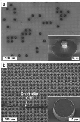
-coated CNTs detached from the substrate, and the remaining CNT pillars densified (Figure 2a). The sample with the thicker
Al2O3coating reached a CHF of 235 W cm−2, without visible structural deformation or detachment (Figure 2b). This comparison suggests that the mechanical reinforcement provided by the Al2O3 coating32 is critical both to resist
capillary densification33 and to improve adhesion to the substrate. Therefore, the lower CHF on CNT micropillars with insufficient Al2O3 coating is likely caused by partial delamination of CNTs during the boiling process.
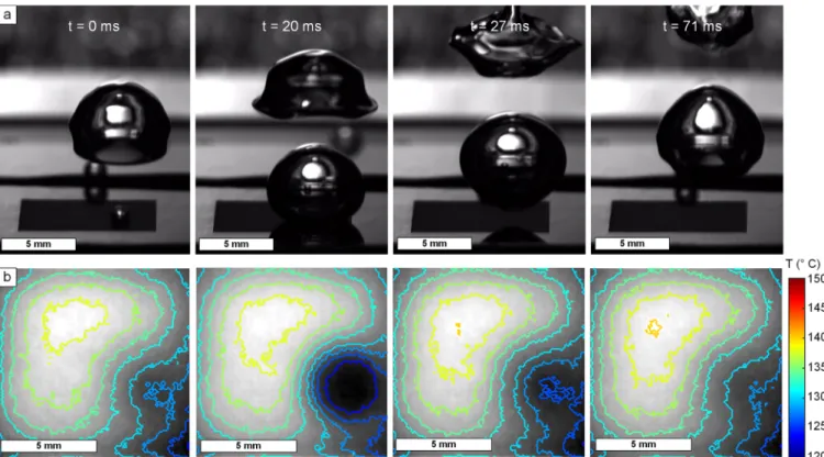
Thus, further pool boiling experiments used CNT surfaces with ALD coating thickness of ∼15 nm and the dimensions stated above (20μm pillar diameter, 5 μm pillar spacing, and 9 μm pillar height). High-speed optical images (Figure 3a) at q″ = 20 W cm−2 show that individual bubbles nucleate on the Al2O3-coated CNT micropillars and grow to their maximum
size (typically 5−6 mm in diameter); then the surrounding liquid rewets the dry spot, with a small macroscopic contact angle on the boiling surface. The bubble then departs, and this periodic process repeats. A synchronized infrared video allows us to correlate the temperature distribution to the bubble dynamics, showing cyclic, temporal cooling of the nucleation site due to bubble formation during a bubble cycle (Figure 3b andVideo S1). At higher heatfluxes (q″ > 50 W cm−2), the bubble density increases dramatically, and the nucleation and departure frequencies also increase (Video S2) before CHF is reached. The CHF values are measured to be 245 and 235 W cm−2on two nominally identical samples. Because the CHF is obtained by gradually increasing the applied heatflux in 5 W cm−2increments, the uncertainty in CHF measurement is∼5 W cm−2. Variation between the two samples may be caused by the surface wettability difference, as the hydrophilicity of Al2O3
Figure 2.Mechanical stability of Al2O3-coated CNT micropillars for
pool boiling: (a) CNTs with 20 ALD cycles of Al2O3coating detach
from the substrate (empty circles) or densify and reach CHF of 150 W cm−2. (b) CNTs with 150 ALD cycles of Al2O3coating remain
stable and attached to the substrate after CHF is reached at 235 W cm−2. Insets show representative micropillars from each case.
degrades with storage time in ambient air, therefore changing its wettability (Figure S5). There is no change within measurement error in the wettability of the Al2O3 surface
before and after the boiling process though (Figure S6) because of the thermal and chemical stability of the Al2O3
coating.34
InFigure 4, boiling curves (i.e., plots of the heatflux versus the substrate superheat) are compared for aflat Al2O3surface,
CNT micropillars with Al2O3coatings of∼15 nm (150 ALD
cycles) and∼50 nm (500 ALD cycles), and silicon micropillars with optimized geometry (data from Rahman et al.2). The measured CHF on the CNT micropillar surface with low porosity is 240 W cm−2, and therefore notably the two Al2O3− CNT samples have nearly identical boiling behavior in spite of the significantly different porosity (∼70% and <10% for the CNTs with ∼15 and ∼50 nm Al2O3, respectively). This
Figure 3.Synchronized high-speed (a) optical and (b) infrared video frames for a single bubble life cycle on a Al2O3−CNT micropillar array with
15 nm Al2O3coating thickness at a heatflux q″ = 20 W cm−2.
Figure 4.SEM images of sidewalls of Al2O3-coated CNT micropillars with (a) 15 nm and (b) 50 nm thick Al2O3coating. (c) Pool boiling curves
on CNT micropillars (20μm pillar diameter, 5 μm spacing, and 9 μm height) with 15 and 50 nm thick Al2O3 coating, Si micropillars with
optimized geometry [reproduced with permission from ref2], andflat Al2O3surface. CHF is signified with an arrow.
suggests that the nanoporosity of the CNT microstructures plays a negligible role in the CHF. However, the CHF on CNT surfaces is much greater than silicon micropillars and flat Al2O3; we attribute this to the microscale geometry and
roughness of the ceramic−CNT micropillars.
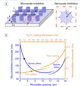
The role of the hierarchical surface geometry on CHF can be understood via the dynamics of liquid imbibition. Liquid imbibition occurs at two length scales (Figure 5a): at the
microscale in the spaces between the CNT pillars and at the nanoscale within the porous CNT forest. The micropillar geometry is represented by a square array of circular micropillars with radius a, pitch p, and height h, and the liquid imbibes the surface from the left to the right, with the imbibition distance Lm. The water contact angle on the flat Al2O3 surface is θ. The microscale imbibition speed can be
approximated based on the balance of the capillary force and the viscous drag. The capillary driving force Fccan be derived
by considering the total surface energy change associated with wetting a unit cell of the micropillars (see the Supporting Information): F p 2 ah (p a)(1 cos ) c 2 2 2 σ π π θ = [ − − − ] (1) The viscous drag at the microscale has two components: viscous drag from the horizontal substrate and from the micropillar sidewalls. Assuming the imbibing liquid front velocity is V, the viscous drag from the substrate (per unit width of the liquidfilm) is estimated as
F V h L p a p 2 1 m 2 2 2 μ π ≈ − (2)
assuming a no-slip boundary condition at the substrate and shear-free top liquid surface. The viscous drag from all the micropillars (per unit width of the liquidfilm) F2is estimated as F fh L p 2 3 2≈ m2 (3) where f is the resisting force per unit length on a cylinder for a uniform incoming flow across a square array of cylinders, whose closed-form expression is given by Sangai and Acrivos.35 A force balance between the capillary driving force and the viscous drag Fc = F1 + F2 can be established to give the
expression of the imbibition time tmfor an imbibition distance Lm: t h ah p a L 2 2 ( )(1 cos ) p a h C m 2( ) 2 3 2 2 m2 2 2 μ σ π π θ ≈ + − − − π − (4) The constant C in eq 4 is a function of the solid volume fraction of the micropillar array expressed as35
C 4 ln 0.738 0.887 2.038 0 0.3 9 2 2 1 0.3 4 1/2 2 3 max 1/2 5/2 max l m ooooo ooooo n ooooo ooooo Ä Ç ÅÅÅÅÅ ÅÅÅÅÅ ÅÅÅ i k jjjjj y{zzzzz É Ö ÑÑÑÑÑ ÑÑÑÑÑ ÑÑÑ π ε ε ε ε ε π ε ε ε ε π = − + − + < < − < < = − − (5) whereε is the solid volume fraction of the pillar arrays a
p 2 2
ε = π . The piecewise expressions of this constant C correspond to two analytical approximations applied to sparse (smalla
p) and
dense (large a
p) arrays of micropillars.
35
Nanoscale imbibition occurs from the edges to the interior of the nanoporous CNT pillars. Applying Darcy’s law in the liquid imbibition direction and the boundary conditions gives the nanoscale imbibition time tn as a function of imbibition
distance Ln t r k L 4 cos n m n2 μϕ σ θ ≈ (6) where k is the permeability,φ is the porosity, and rmis the pore radius.22 The nanoscale permeability can be estimated based on a similar approximation of flow across a square array of nanoscale cylinders, which also have two regimes correspond-ing to sparse (thin Al2O3 coating) and dense (thick Al2O3 coating) arrays of Al2O3−CNTs (see the Supporting
Information). Note here the CNT height h does not come into play due to the extremely high aspect ratio of the individual CNTs.
The imbibition distance for a micropillar is roughly its radius. For micropillars with a radius of 10μm and ∼15 nm Al2O3coating, the calculated time scale over a length equal to
the pillar radius Ln= 10μm is tn∼ 0.1 ms according toeq 6. In contrast, the microscale imbibition time scale is tm∼ 200 ms
(eqs 4 and 5; Figure 5a, left). Here a microscale imbibition distance of Lm = 2 mm is assumed from the typical bubble
radius observed at heatfluxes close to CHF. This indicates that liquidfills the CNT pillars rapidly considering the time scale of microscale imbibition at bubble size (tn≪ tm because Ln ≪ Lm). Despite the fact that the speed of nanoscale imbibition is
Figure 5.Analysis of microscale and nanoscale liquid imbibition on Al2O3-coated CNT microstructured surfaces. (a) Schematic of
microscale (left) and nanoscale (right) imbibition. (b) Time scales for microscale and nanoscale imbibition as functions of micropillar spacing and Al2O3 coating thickness, respectively. Dots indicate
experiment values for Al2O3-coated CNT micropillars with 20 μm
pillar diameter, 5μm pillar spacing, 9 μm pillar height, and 15 nm Al2O3coating thickness.
much slower than that of microscale imbibition (tn≫ tmif Ln= Lm) due to the large viscous drag inside the nanopores, the
difference in the imbibition distance becomes the dominating factor. We conclude that the rewetting dynamics after bubble detachment are dominated by the rate of microscale imbibition, and the nanoporosity has little influence on the surface rewetting and resultant CHF. Indeed, the similarity of the CHF values and boiling curves comparing the highly porous versus solid CNT surfaces at heatfluxes greater than 60 W cm−2(Figure 4c) suggests that the nanoscale imbibition has a negligible effect on the vaporization and liquid rewetting processes at high heatfluxes.
At low heatfluxes (<60 W cm−2), we analyzed the frequency and diameter of bubble departure from infrared imaging (Figure S7, see detailed in theSupporting Information). We found that both the bubble departure diameter and bubble cycle time are smaller on the nanoporous surface than those on the solid micropillar surface, and both decrease with increasing heatfluxes on the nanoporous pillar surface (Figure S8). This implies that the porosity of the CNT micropillars, combined with their roughness, influences the bubble dynamics at low heat fluxes. The effect of this nanoimbibition on the bubble dynamics and boiling characteristics may require further studies through high-resolution temperature measurement.36
The CHF value of 245 W cm−2achieved on ceramic−CNT microstructured surfaces is among the highest reported for superhydrophilic surfaces in water pool boiling at atmospheric pressure.37 The nanotextures of the pillar surface effectively reduce the local water contact angle to zero regardless of the porosity, thereby giving rapid liquid rewetting of the hot spots upon bubble departure. To our knowledge, the highest reported CHF on superhydrophilic surfaces in previous literature is 257 W cm−2 for microstructured silicon coated with virus-templated nickel nanostructures.2 The effective superhydrophilicity of the Al2O3-coated CNTs and nanoscale imbibition also give greater heatflux than Si micropillars with optimized geometry shown (CHF = 217 W cm−2) inFigure 4c (orange curve, reported by Rahman et al.2), and Si micropillars with optimized geometry and nanoscale surface textures (CHF = 211 W cm−2).1
We hypothesize that even greater CHF could be achieved by improving the hydrophilicity of the coating on the CNTs and by optimizing the microstructure geometry with a slightly larger spacing, as shown in Figure 5b and the imbibition analysis in the Supporting Information. Also, CHF of 420 W cm−2 has been reported by Kandlikar et al. using a different macroconvection mechanism, where channels with submillim-eter width are used to generate separate liquid−vapor pathways for bubble nucleation and departure.38,39This design based on macroconvection could also be easily implemented with micropatterned CNT surfaces, and CNTs may also enable optimization of the passive liquid wicking via nanoporosity. All the CNT−Al2O3 structures with the Al2O3 coating thickness
above 15 nm remain attached to the substrate after our boiling tests, therefore demonstrating structural stability of the texture. Moreover, roll-to-roll patterning and CVD and ALD processes that can be performed over large areas at atmospheric pressure40 suggest that CNT-based microstructured boiling surfaces could be manufactured cost-effectively in large-area formats, including on metal substrates and tubes.41,42
■
CONCLUSIONSIn summary, wefind that Al2O3-coated CNT microstructures
exhibit a high CHF (245 W cm−2) due to rapid liquid imbibition imparted by their stable microscale geometry and nanoscale texture. Even higher CHF could potentially be achieved by increasing the hydrophilicity of the conformal coating and by optimizing the microstructure pattern. It may also be possible to estimate the CHF by modeling that considers the microscale structure, nanoscale coating, and local surface wettability. Investigation of the influences of these parameters on the heat transfer coefficient is also of interest for future study. Methods of shaping CNT microstructures into more complex geometries43,44 could enable surfaces designed to tailor bubble nucleation and guide bubble departure. Moreover, the electrical conductivity of CNTs could make them useful in manipulating bubble dynamics by using electric forces.45 Finally, CNTs can be produced on metal foil substrates in a roll-to-roll fashion, suggesting promise for large-scale manufacturing of such engineered surfaces for boiling heat transfer applications.
■
ASSOCIATED CONTENT*
S Supporting InformationThe Supporting Information is available free of charge on the
ACS Publications websiteat DOI:10.1021/acsanm.9b01116. Figures S1−S8 (PDF) Video S1 (AVI) Video S2 (AVI)
■
AUTHOR INFORMATION Corresponding Author *[email protected]. ORCID Hangbo Zhao:0000-0001-5229-4192 Kripa K. Varanasi:0000-0002-6846-152X A. John Hart:0000-0002-7372-3512 NotesThe authors declare no competingfinancial interest.
■
ACKNOWLEDGMENTSFinancial support was provided by the MIT Center for Clean Water and Clean Energy supported by the King Fahd University of Petroleum and Minerals, the Air Force Office of Scientific Research (FA9550-16-1-0011), and the MIT-Skoltech Next Generation Program. Thinfilm deposition and patterning were performed at the MIT Microsystems Technology Laboratories (MTL). Electron microscopy was performed at the MIT Center for Materials Science and Engineering (CMSE).
■
REFERENCES(1) Dhillon, N. S.; Buongiorno, J.; Varanasi, K. K. Critical Heat Flux Maxima During Boiling Crisis on Textured Surfaces. Nat. Commun. 2015, 6, 8247.
(2) Rahman, M. M.; Ölçeroǧlu, E.; McCarthy, M. Role of Wickability on the Critical Heat Flux of Structured Superhydrophilic Surfaces. Langmuir 2014, 30 (37), 11225−11234.
(3) Liter, S. G.; Kaviany, M. Pool-Boiling Chf Enhancement by Modulated Porous-Layer Coating: Theory and Experiment. Int. J. Heat Mass Transfer 2001, 44 (22), 4287−4311.
(4) Chen, R.; Lu, M.-C.; Srinivasan, V.; Wang, Z.; Cho, H. H.; Majumdar, A. Nanowires for Enhanced Boiling Heat Transfer. Nano Lett. 2009, 9 (2), 548−553.
(5) Shim, D. I.; Choi, G.; Lee, N.; Kim, T.; Kim, B. S.; Cho, H. H. Enhancement of Pool Boiling Heat Transfer Using Aligned Silicon Nanowire Arrays. ACS Appl. Mater. Interfaces 2017, 9 (20), 17595− 17602.
(6) Chu, K.-H.; Enright, R.; Wang, E. N. Structured Surfaces for Enhanced Pool Boiling Heat Transfer. Appl. Phys. Lett. 2012, 100 (24), 241603.
(7) Kruse, C. M.; Anderson, T.; Wilson, C.; Zuhlke, C.; Alexander, D.; Gogos, G.; Ndao, S. Enhanced Pool-Boiling Heat Transfer and Critical Heat Flux on Femtosecond Laser Processed Stainless Steel Surfaces. Int. J. Heat Mass Transfer 2015, 82, 109−116.
(8) Gregorčič, P.; Zupančič, M.; Golobič, I. Scalable Surface Microstructuring by a Fiber Laser for Controlled Nucleate Boiling Performance of High- and Low-Surface-Tension Fluids. Sci. Rep. 2018, 8 (1), 7461.
(9) Pop, E.; Mann, D.; Wang, Q.; Goodson, K. E.; Dai, H. J. Thermal Conductance of an Individual Single-Wall Carbon Nanotube above Room Temperature. Nano Lett. 2006, 6 (1), 96−100.
(10) Fabris, D.; Rosshirt, M.; Cardenas, C.; Wilhite, P.; Yamada, T.; Yang, C. Y. Application of Carbon Nanotubes to Thermal Interface Materials. J. Electron. Packag. 2011, 133 (2), 020902.
(11) Kaur, S.; Raravikar, N.; Helms, B. A.; Prasher, R.; Ogletree, D. F. Enhanced Thermal Transport at Covalently Functionalized Carbon Nanotube Array Interfaces. Nat. Commun. 2014, 5, 3082.
(12) Boo, C.; Elimelech, M. Thermal Desalination Membranes: Carbon Nanotubes Keep up the Heat. Nat. Nanotechnol. 2017, 12 (6), 501−503.
(13) Huang, Y.-T.; Zhang, H.; Wan, X.-J.; Chen, D.-Z.; Chen, X.-F.; Ye, X.; Ouyang, X.; Qin, S.-Y.; Wen, H.-X.; Tang, J.-N. Carbon Nanotube-Enhanced Double-Walled Phase-Change Microcapsules for Thermal Energy Storage. J. Mater. Chem. A 2017, 5 (16), 7482−7493. (14) Sarafraz, M. M.; Hormozi, F.; Silakhori, M.; Peyghambarzadeh, S. M. On the Fouling Formation of Functionalized and Non-Functionalized Carbon Nanotube Nano-Fluids under Pool Boiling Condition. Appl. Therm. Eng. 2016, 95, 433−444.
(15) Sarafraz, M. M.; Hormozi, F.; Peyghambarzadeh, S. M. Pool Boiling Heat Transfer to Aqueous Alumina Nano-Fluids on the Plain and Concentric Circular Micro-Structured (CCM) Surfaces. Exp. Therm. Fluid Sci. 2016, 72, 125−139.
(16) Cai, Q.; Chen, C.-L. Design and Test of Carbon Nanotube Biwick Structure for High-Heat-Flux Phase Change Heat Transfer. J. Heat Transfer 2010, 132 (5), 052403.
(17) Cui, Y.; Liu, C.; Hu, S.; Yu, X. The Experimental Exploration of Carbon Nanofiber and Carbon Nanotube Additives on Thermal Behavior of Phase Change Materials. Sol. Energy Mater. Sol. Cells 2011, 95 (4), 1208−1212.
(18) Dharmendra, M.; Suresh, S.; Kumar, C. S. S.; Yang, Q. Pool Boiling Heat Transfer Enhancement Using Vertically Aligned Carbon Nanotube Coatings on a Copper Substrate. Appl. Therm. Eng. 2016, 99, 61−71.
(19) Lee, S.; Seo, G. H.; Lee, S.; Jeong, U.; Lee, S. J.; Kim, S. J.; Choi, W. Layer-by-Layer Carbon Nanotube Coatings for Enhanced Pool Boiling Heat Transfer on Metal Surfaces. Carbon 2016, 107, 607−618.
(20) Ahn, H. S.; Sinha, N.; Zhang, M.; Banerjee, D.; Fang, S.; Baughman, R. H. Pool Boiling Experiments on Multiwalled Carbon Nanotube (MWCNT) Forests. J. Heat Transfer 2006, 128 (12), 1335−1342.
(21) Ujereh, S.; Fisher, T.; Mudawar, I. Effects of Carbon Nanotube Arrays on Nucleate Pool Boiling. Int. J. Heat Mass Transfer 2007, 50 (19), 4023−4038.
(22) Zhao, H.; Jacob, C.; Stone, H. A.; Hart, A. J. Liquid Imbibition in Ceramic-Coated Carbon Nanotube Films. Langmuir 2016, 32 (48), 12686−12692.
(23) Bertossi, R.; Caney, N.; Gruss, J. A.; Dijon, J.; Fournier, A.; Marty, P. Influence of Carbon Nanotubes on Deionized Water Pool Boiling Performances. Exp. Therm. Fluid Sci. 2015, 61, 187−193.
(24) Oliver, C. R.; Polsen, E. S.; Meshot, E. R.; Tawfick, S.; Park, S. J.; Bedewy, M.; Hart, A. J. Statistical Analysis of Variation in Laboratory Growth of Carbon Nanotube Forests and Recommenda-tions for Improved Consistency. ACS Nano 2013, 7 (4), 3565−3580. (25) Dash, S.; Rapoport, L.; Varanasi, K. K. Crystallization-Induced Fouling During Boiling: Formation Mechanisms to Mitigation Approaches. Langmuir 2018, 34 (3), 782−788.
(26) Lushington, A.; Liu, J.; Tang, Y.; Li, R.; Sun, X. Surface Modification of Nitrogen-Doped Carbon Nanotubes by Ozone via Atomic Layer Deposition. J. Vac. Sci. Technol., A 2014, 32 (1), 01A124.
(27) Azimi, G.; Dhiman, R.; Kwon, H.-M.; Paxson, A. T.; Varanasi, K. K. Hydrophobicity of Rare-Earth Oxide Ceramics. Nat. Mater. 2013, 12 (4), 315−320.
(28) Karaman, M. E.; Antelmi, D. A.; Pashley, R. M. The Production of Stable Hydrophobic Surfaces by the Adsorption of Hydrocarbon and Fluorocarbon Carboxylic Acids onto Alumina Substrates. Colloids Surf., A 2001, 182 (1−3), 285−298.
(29) Xiao, R.; Enright, R.; Wang, E. N. Prediction and Optimization of Liquid Propagation in Micropillar Arrays. Langmuir 2010, 26 (19), 15070−15075.
(30) Ishino, C.; Reyssat, M.; Reyssat, E.; Okumura, K.; Quéré, D. Wicking within Forests of Micropillars. EPL 2007, 79 (5), 56005.
(31) Bedewy, M.; Meshot, E. R.; Reinker, M. J.; Hart, A. J. Population Growth Dynamics of Carbon Nanotubes. ACS Nano 2011, 5 (11), 8974−8989.
(32) Brieland-Shoultz, A.; Tawfick, S.; Park, S. J.; Bedewy, M.; Maschmann, M. R.; Baur, J. W.; Hart, A. J. Scaling the Stiffness, Strength, and Toughness of Ceramic-Coated Nanotube Foams into the Structural Regime. Adv. Funct. Mater. 2014, 24 (36), 5728−5735. (33) Tawfick, S.; Zhao, Z.; Maschmann, M.; Brieland-Shoultz, A.; De Volder, M.; Baur, J. W.; Lu, W.; Hart, A. J. Mechanics of Capillary Forming of Aligned Carbon Nanotube Assemblies. Langmuir 2013, 29 (17), 5190−5198.
(34) Correa, G. C.; Bao, B.; Strandwitz, N. C. Chemical Stability of Titania and Alumina Thin Films Formed by Atomic Layer Deposition. ACS Appl. Mater. Interfaces 2015, 7 (27), 14816−14821. (35) Sangani, A. S.; Acrivos, A. Slow Flow Past Periodic Arrays of Cylinders with Application to Heat Transfer. Int. J. Multiphase Flow 1982, 8 (3), 193−206.
(36) Bucci, M.; Richenderfer, A.; Su, G.-Y.; McKrell, T.; Buongiorno, J. A Mechanistic IR Calibration Technique for Boiling Heat Transfer Investigations. Int. J. Multiphase Flow 2016, 83, 115− 127.
(37) Cho, H. J.; Preston, D. J.; Zhu, Y. Y.; Wang, E. N. Nanoengineered Materials for Liquid-Vapour Phase-Change Heat Transfer. Nat. Rev. Mater. 2016, 2 (2), 16092.
(38) Kandlikar, S. G. Controlling Bubble Motion over Heated Surface through Evaporation Momentum Force to Enhance Pool Boiling Heat Transfer. Appl. Phys. Lett. 2013, 102 (5), 051611.
(39) Jaikumar, A.; Kandlikar, S. G. Ultra-High Pool Boiling Performance and Effect of Channel Width with Selectively Coated Open Microchannels. Int. J. Heat Mass Transfer 2016, 95, 795−805. (40) Mousa, M. B. M.; Oldham, C. J.; Parsons, G. N. Atmospheric Pressure Atomic Layer Deposition of Al2O3 Using Trimethyl
Aluminum and Ozone. Langmuir 2014, 30 (13), 3741−3748. (41) Hiraoka, T.; Yamada, T.; Hata, K.; Futaba, D. N.; Kurachi, H.; Uemura, S.; Yumura, M.; Iijima, S. Synthesis of Single- and Double-Walled Carbon Nanotube Forests on Conducting Metal Foils. J. Am. Chem. Soc. 2006, 128 (41), 13338−13339.
(42) Pattinson, S. W.; Viswanath, B.; Zakharov, D. N.; Li, J.; Stach, E. A.; Hart, A. J. Mechanism and Enhanced Yield of Carbon Nanotube Growth on Stainless Steel by Oxygen-Induced Surface Reconstruction. Chem. Mater. 2015, 27 (3), 932−937.
(43) Park, S. J.; Zhao, H.; Kim, S.; De Volder, M.; Hart, A. J. Predictive Synthesis of Freeform Carbon Nanotube
tures by Strain-Engineered Chemical Vapor Deposition. Small 2016, 12 (32), 4393−4403.
(44) Zhao, H.; Park, S. J.; Solomon, B. R.; Kim, S.; Soto, D.; Paxson, A. T.; Varanasi, K. K.; Hart, A. J. Synthetic Butterfly Scale Surfaces with Compliance-Tailored Anisotropic Drop Adhesion. Adv. Mater. 2019, 31 (14), 1807686.
(45) Di Marco, P; Morganti, N; Saccone, G. Electric Field Effects on the Dynamics of Bubble Detachment from an Inclined Surface. J. Phys.: Conf. Ser. 2015, 655 (1), 012044.