2425 Copyright ⓒ The Korean Institute of Electrical Engineers
Electrical and Thermo-mechanical Properties of DGEBA Cycloaliphatic
Diamine Nano PA and SiO
2Composites
Pavel Trnka
†, Vaclav Mentlik*, Lukas Harvanek*, Jaroslav Hornak* and Libor Matejka**
Abstract
– This study investigates a new organic based material and its dielectric and mechanical properties. It is a comprehensive nanocomposite comprising a combination of various types of nanofillers with hydrophobic silica nanoparticles (AEROSIL R 974) as a matrix modifier and a polyamide nano nonwoven textile, Ultramid-Polyamide 6, pulped in the electrostatic field as a dielectric barrier. The polymer matrix is an epoxy network based on diglycidyl ether of bisphenol A (DGEBA) and cycloaliphatic diamine (Laromine C260). The designed nanocomposite material is an alternative to the conventional three-component composites containing fiberglass and mica with properties that exceed current electroinsulating systems (volume resistivity on the order of 1016 Ω·m, dissipation factor tan δ = 4.7·10-3, dielectric strength 39 kV/mm).Keywords:
Dielectric, Nanocomposite, Nonwoven, Polyamide, Thermo-mechanical properties.1. Introduction
The three-component composite systems currently used in high-voltage engineering to create a dielectric barrier, e.g., for main wall insulation of rotary machines, are heterogeneous and contain macroscopic inorganic components [1]. They primarily use glass fabric as a carrier [2, 3]. PET (polyethylene terephthalate) or PI (polyimide) films are also widely used [4]. The second component - a dielectric barrier - is reconstructed mica manufactured into mica paper [5, 6]. The third component - the matrix - is an epoxy [7], polyester [8] or silicone resin [9]. These materials are characterized by a volume resistivity, ρv, of 1013Ω·m,
dissipation factor, tan δ, of 0.015, dielectric strength, Ds, of 35kV/mm [10] and glass transition temperature, Tg, of 115°C [11]. However, the properties vary with the com-ponents and manufacturer, making generalization impossible. Currently, there is no synthetic insulating material that meets all the requirements for high-voltage insulation systems and not containing a macroscopic inorganic component (e.g. dielectric barrier). A similar situation occurs with electrical insulating systems for F thermal class (155°C and higher) [12]. New elements in this area include polymer nanocom-posites consisting of a polymer matrix with a microphase-separated nanofiller, enabling improvement of its properties, e.g., a decrease in the accumulated space charge and reduction of the internal electrical stress [13].
The first use of nanofillers in the field of high-voltage EIS (electrical insulating systems) occurred in 1988, when
one of the first patents in this area [14] (US Pat. 4760296) describes the benefits of adding a filler of submicron dimensions to an insulation system based on epoxy resin and mica in the main coil insulation generators. Similar work [15] was focused on silicon micro- and nanoparticles and the influence of reducing the filler particle size to increase the voltage resistance of polymers. The theoretical treatise of Lewis in 1994 was a milestone [16] and the origin of interest in nanodielectrics. An increase in worldwide interest in this area and several experiments occurred after the publication of practically oriented research [17]. Systems with different polymer matrices and nanofillers are currently studied for use in the field of nanodielectrics. The most commonly used matrix polymers are epoxides or polyolefins [18]. Thermoplastics such as polystyrene [19] and polyamide [20] are also used. Thermoplastic nanocomposites have easier workability and can be recycled [21]. However, in terms of the mechanical and thermal properties and their resistance to aggressive environments, nanocomposites based on epoxides are preferred. Regarding nanofillers, attention is primarily devoted to layered silicates (clays) [22] and inorganic oxides (SiO2 [23], TiO2 [24], Al2O3 [25], ZnO [26], MgO
[27], BN [28]). Other study was focused on investigation of the electrical properties of nanocomposites containing POSS (polyhedral oligomeric silsesquioxanes) [29]. The basic requirement in preparation of polymer nanocom-posites is homogenous dispersion of the nanofiller in the matrix, reducing the aggregation of large clusters. Large clusters usually lead to a deterioration in the final properties of the composite. The interaction of polymer and nanofiller plays an important role. Weather it is a polar or non-polar substance also affects the resulting electrical properties [30].
Also thermo-mechanical properties of epoxy-based
† Corresponding Author: Faculty of Electrical Engineering, University of West Bohemia, Czech Republic. ([email protected])
* Faculty of Electrical Engineering, University of West Bohemia, Czech Republic. ({mentlik,harvy, jhornak}@ket.zcu.cz)
** Institute of Macromolecular Chemistry, Academy of Sciences of the Czech Republic, Czech Republic. ([email protected])
micro- and nanocomposites were investigated by Dynamic Mechanical Analysis (DMA) or Thermal Gravimetric Analysis in a few studies (e.g. [31, 32]), where the shear modulus, G’, and mechanical loss factor, tan δ, were used for estimation of glass transition temperature, Tg. Mass loss, m, is also the key parameters for evaluation of thermal stability of dielectric material. There are a variation of changes of investigated parameters depending on the filler type and size [33], effect of moisture, reduced crosslink density of epoxy matrix or imbalanced stoichiometry between resin and hardener [34].
The aim of this study was to prepare a new electrical insulating material - a complex nanocomposite – that lacks a macroscopic inorganic component and has the same or improved properties compared to existing material of the same class.
We studied polymeric nanocomposites containing epoxy matrix modified by nanofillers based on nanoparticles and polymeric nanofabric applied as a dielectric barrier of the composite. The polymer matrix of nanocomposite forms an epoxy-amine network using a classic epoxy resin - diglycidyl ether of bisphenol A (DGEBA), crosslinked cycloaliphatic diamine 3,3'-dimethyl-4,4' diaminocyklohexylmetan (Laromine C260). This matrix was chosen due to its excellent properties such as high thermal and chemical resistance, high strength, environmental resistance, excellent adhesion to different surfaces and ease of curing without formation of volatile compounds. This resin also helps increase the glass transition temperature, Tg, because it is reduced by the addition of SiO2 nanoparticles and polyamide
(PA) [35]. The nanofiller used to improve the electrical properties of the matrix was hydrophobic nanosilica. Hydrophobized nanosilica at a low volume concentration was used because there is a negative impact of large volumes of nanoparticles on electrical and other properties [35]. A nonwoven nanofibrous layer based on Polyamide 6 created the dielectric barrier of the composite.
The main focus is on study of the influence of the composition of the nanocomposite on the electrical and thermo-mechanical properties, thermal stability and optimi-zation of the developed material composition.
2. Composite Components
This section includes details regarding individual composite components and the preparation of the samples. 2.1 Polymer matrix
The polymeric matrix was an epoxy network with a resin
based on diglycidyl ether of bisphenol A (DGEBA); see Fig. 1. The epoxide equivalent weight, EEW, was 187 g/mol. As a crosslinker, cycloaliphatic diamine, 3,3'-dimethyl-4,4'diamino-cyclohexylmethane (Laromine C260) was applied. The equivalent weight of the NH groups, AHEW, was 59.5 g/eq. Resin based on bisphenol A is the most common epoxy resin and is applicable in a wide range of products. Its applications in industry include preparation of matrix for composites, potting compounds, adhesives, coatings, and lamination mixtures. Using a cycloaliphatic diamine as a hardener leads to formation of a network with a high glass transition, Tg, and very good mechanical properties. describes how to prepare each part of the final manuscript more specifically.
2.2 Nanofillers
The hydrophobic silica AEROSIL R 974 is modified silica (silicon dioxide) with a specific surface area of 200 m2/g containing 12 nm nanoparticles. The hydrophobic
character of the particles has a positive impact on composites in comparison with hydrophilic ones.
2.3 Nanofabric, Ultramid – Polyamid 6
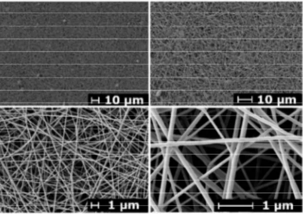
The nanofibrous layer of polyamide 6 (NAP), with a molecular weight of 30.000 g/mol, is suitable for this purpose due to its low viscosity. The SEM images in Fig. 2 show the polyamide nanofiber layer. It is most favorable for the formation of nanofibers in an electrostatic field [36]. The fibers are formed from a polymer solution consisting of 13% polyamide 6 and 87% formic acid/acetic acid at a 2:1 ratio, with a final viscosity of 436.3 mP/s. The produced nanofibers have suitable mechanical properties and advantageous hydrophobicity. These are advantageous prerequisites for handling the fiber layers.
They also appear to have a relatively favorable starting material cost. The melting point of the polyamide (ISO 3146) is 220°C, the density (ISO 1183) is 1.12 to 1.15 g/cm3, the round pellets are 2 - 2.5 mm, and the water absorption after saturation in 23°C water is 8.5%. The
Fig. 2. SEM images of the nanofiber Fig. 1. Formula of epoxy resin based on DGEBA
homogeneity of the nanofiber is evident, and the number of defects is minimal. The fibers are cylindrical without significant deviations from the mean diameter of 98.9 nm and have a standard deviation of 20.8 nm and variation coefficient of 21%. The basis weight of the prepared layer is 4 g/m2, and the thickness is 84 μm, filled up to 25 to 30% with 8 to 11% moisture absorption.
2.4 The reactive diluent
For better homogenization of the system and saturation of the nanofabric, reactive diluent phenylglycidylether (PGE) was used at concentrations from 5 to 20 mol% of the total epoxy group content, or 4-20 weight percent relative to the DGEBA. In the experiments, we observed the effect of the diluent on the resulting product properties. 2.5 Sample preparation
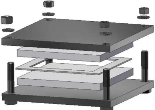
Specially made separable molds (see Fig. 3) consisting of two polished steel plates (170 ´ 170 ´ 10 mm) were used for the nanocomposite sample preparation. To ensure
optimal conditions and prevent the possibility of adhesion between the steel and the samples, 130 ´ 130 ´ 10 mm Teflon plates were inserted.
The epoxy network was prepared by reacting DGEBA with a diamine (Laromine) in a stoichiometric ratio of functional groups (weight equivalent) of Cepoxy: CNH = 1:1.
In cases of a reactive diluent, part of the diepoxide DGEBA was replaced by PGE monoepoxide so that the total concentration of the epoxy groups remained constant. The processing technology is important for the quality of the samples, particularly the homogeneity of the material and the absence of air inhomogeneities.
An overview of the steps of the sample preparation process is shown in Fig. 4.
When preparing the polymer network, the correct weight ratios of the components, sequence of the process steps, time limits of vacuum during mixing and temperature during curing were precisely monitored
3. Experiment
Commonly known phenomenological AC and DC electric methods were used to determine the basic electrical properties of the nanocomposites.
3.1 Volume resistivity measurement
Dielectric absorption measurements were used to evaluate the volume resistivity, ρv (Ω·m), and polarization
index, pi (-) (ratio of absorption currents in 15 s and 60 s
or 60 s and 600 s), of the samples according to standard IEC 62631-3-2 [37]. A Keithley 6517 electrometer was used with a Keithley model 8009 three-electrode measuring system with a 50-mm diameter measuring electrode,
75-Fig. 4. Overview of the sample preparation Fig. 3. The mold used to cast the samples
mm outer diameter shielding electrode and 1-mm gap. The measuring system was placed in a small screen room to eliminate the influence of external electrical fields. Before measurement, the samples were conditioned and discharged (24 hours). Stable temperature and humidity (45% r.h.) were ensured during measurement. The measurement was controlled using an automatic measuring system with Agilent VEE Pro software.
The volume resistivity was calculated using (1)
(
W×m)
× × = I t V A c ef Vr
, (1)where ρv is the volume resistivity (Ω·m), V is the applied
voltage (V), tc is the average sample thickness in the area
of the electrode (m), I is the current at time 6000 s (A) and Aef is the effective electrode surface (m2).
3.2 Dissipation factor measurement
The dissipation factor tan δ (-) was measured using a Tettex 2830/2831 solid dielectrics analyzer with a Tettex 2914 three-electrode measuring system and temperature and pressure control according to standard IEC 60250 [38]. 3.3 Dielectric strength measurement
The dielectric strength Ds (kV/mm) was measured
according to standard IEC 60243-1 [39] and determined according to Eq. (2)
Ds = Vbr / tc (2)
where Vbr is the breakdown voltage (kV) and tc is the
average sample thickness in the area of the electrode (m/1000).
A special electrode system was constructed for this measurement, with 6-mm diameter electrodes in precise planar alignment. Maximal use of the sample area results in more measured data (BDV – breakdown voltage). The BDV voltage evaluation occurred while the sample was submerged in insulating mineral oil [40] (10 BDV per sample) to compare each set of samples during the experimental phases. A 200 kV high-voltage laboratory source was used as the source of the test voltage with 50 Hz AC. The effective BDV was measured using a BDV detector.
3.4 Dynamic Mechanical Analysis (DMA)
DMA of nanocomposite samples was conducted using an ARES G2 (TA Instruments). Oscillatory shear deformation was applied at a frequency of 1 Hz and at 20-250°C with a temperature increase of 3 °C·min-1. The glass transition
temperature, Tg, was determined from the position of the maximum mechanical loss factor, tan δ. The shear modulus
was determined in a rubbery state at 200 °C. 3.5 Thermogravimetric Analysis (TGA)
TGA measurements were performed using a Pyris 1 Perkin Elmer Thermogravimetric Analyzer under air atmosphere. The measuring temperature interval was 30-880 °C with a 10 °C temperature rise, 50 ml·min-1 gas flow and approximately 10 mg sample.
4. Results and Discussions
The influences of the individual components (i.e., silica nanofillers and polyamide nanofabric (NAP), diluent PGE) of the new nanocomposite were studied to optimize its composition for high-voltage insulation (optimum thermal, mechanical and electrical properties, low measured data dispersion). The electrical and thermomechanical properties of the material and its thermal stability were studied.
The optimum amount of hydrophobic nanosilica in the matrix was 1%. Higher and lower volumes of nanosilica did not improve the electrical properties.
The fluidity of the epoxy resin (to nanofabric) was adjusted using the reactive diluent phenylglycidyl ether PGE (10%).
4.1 Electrical properties of nanocomposite
The volume resistivity and one-minute polarization index were evaluated from the dielectric absorption data. The volume resistivity data are shown in Table 3.
From the results, considerable improvement is evident, i.e., an increase of volume resistivity due to inclusion of hydrophobic nanosilica in the matrix, from 3.2·1015 to 2.7·1016 Ω·m (three orders of magnitude higher than the conventional material); however, there is only a slight increase in the dispersion of values compared to the matrix only). The PGE diluent decreased the resistivity, and the dispersion of its values was significantly reduced. The resulting resistivity is close to that of the pure resin without additives. The DGEBA-Laromine-SiO2-NPA
nano-composite (containing hydrophobic silica increasing the volume resistivity and nanofabric with a positive influence on the dielectric strength of the nanocomposite) has a lower volume resistivity than samples containing silica SiO2 only, 2.8·1016 Ω·m, and lower dispersion of the values,
which suggests better consistency of the results. The resistivity of this nanocomposite is higher and therefore more favorable than a mixture with the diluent PGE. Thus, the DGEBA-Laromine-SiO2-NPA nanocomposite is
the preferred system.
A similar trend can be observed in the polarization index results.
Another variable that reveals the behavior of these nano-composites in an electric field is the relative permittivity.
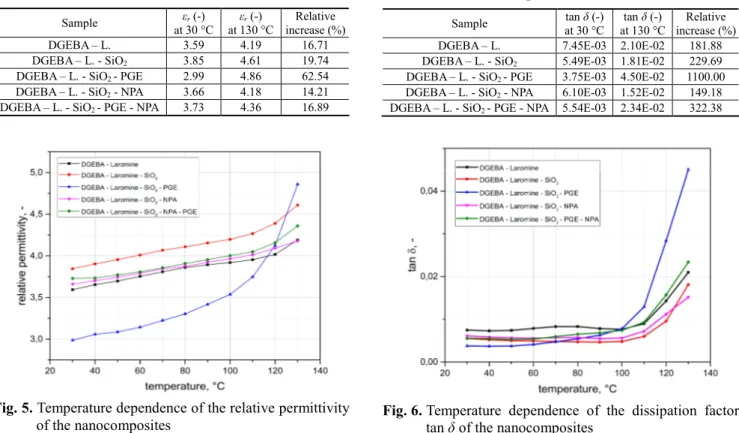
Its dependence on temperature was studied, and the results are shown in Fig. 5 with a comparison of the nanocomposites in Table 1.
Table 1 shows the differences in permittivity corres-ponding to a temperature rise of 100°C. The DGEBA – Laromine - SiO2 - PGE nanocomposite exhibits strong
temperature dependence (εr 30°C = 2.987 and εr 130 °C =
4.86, a relative increase of 62.54%). The other nano-composites exhibit only a slight increase in the relative permittivity in the observed temperature range. The DGEBA - Laromine - SiO2 - NPA nanocomposite has the
lowest temperature dependence of all samples investigated in this temperature range (the difference between 30 and 130°C is only 14,21%). We can conclude that nano-composites without PGE have lower thermal dependence, εr. These samples are relatively stable at a suitable εr.
Regarding the dissipation factor tan δ, if we look at its temperature dependence from 30 to 130 °C (Fig. 6), we can observe the lowest losses for the DGEBA - Laromine - SiO2 - NPA nanocomposite at temperatures above 80 °C.
This nanocomposite exhibits stable tan δ (0.0061– 0.0057) in the 30 to 80°C interval. This nanocomposite composition is optimal in terms of dielectric losses. The negative effect of PGE is notable because although the composite has the lowest tan δ at 30 °C, it exhibits a steep increase above 80°C (0.045). The other samples exhibit steeper increases and higher dissipation factors at higher temperatures.
Table 2 illustrates the dissipation factor curves as the temperature increases 30 to 130°C. The DGEBA - Laromine - SiO2 - NPA nanocomposite exhibits the lowest change
here. The dielectric strengths of the studied nanocomposites Table 1. The change in relative permittivity with an
increase in temperature of 100 °C Sample εr (-) at 30 °C εr (-) at 130 °C Relative increase (%) DGEBA – L. 3.59 4.19 16.71 DGEBA – L. - SiO2 3.85 4.61 19.74
DGEBA – L. - SiO2 - PGE 2.99 4.86 62.54
DGEBA – L. - SiO2 - NPA 3.66 4.18 14.21
DGEBA – L. - SiO2 - PGE - NPA 3.73 4.36 16.89
Fig. 5. Temperature dependence of the relative permittivity of the nanocomposites
Table 3. Electrical parameters and their standard deviations of the studied nanocomposites (measured at 500 V)
Sample Ri (Ω) pi1 (-) pi10 (-) ρv (Ω·m) tan δ (-) εr (-) Ds (kV/mm)
DGEBA – Laromine 3.21E+15 3.41 5.46 5.37E+15 7.70E-03 3.59 37.7
Standard deviation 2.59E+15 1.11 3.35 4.06E+15 1.36E-03 0.54 0.85
DGEBA - Laromine - SiO2 2.71E+16 3.99 7.82 4.95E+16 7.36E-03 3.85 38.3
Standard deviation 2.22E+16 0.15 1.08 3.83E+16 1.52E-04 0.07 0.56
DGEBA - Laromine - SiO2 - PGE 6.28E+15 3.47 6.64 1.03E+16 4.48E-03 2.99 35.8
Standard deviation 1.23E+15 0.32 1.48 1.48E+15 2.72E-04 0.24 0.63
DGEBA - Laromine - SiO2 - NPA 2.80E+16 3.59 7.5 3.32E+16 4.70E-03 3.66 39
Standard deviation 1.95E+16 0.76 1.66 2.18E+16 1.32E-03 0.19 0.86
DGEBA - Laromine - SiO2 - PGE - NPA 1.69E+16 3.33 8.13 2.64E+16 5.55E-03 3.73 36
Standard deviation 1.69E+16 0.19 3.35 2.76E+16 4.48E-04 0.13 0.63
Table 2. The change in relative permittivity with an increase in temperature of 100 °C Sample tan δ (-) at 30 °C tan δ (-) at 130 °C Relative increase (%)
DGEBA – L. 7.45E-03 2.10E-02 181.88
DGEBA – L. - SiO2 5.49E-03 1.81E-02 229.69
DGEBA – L. - SiO2 - PGE 3.75E-03 4.50E-02 1100.00
DGEBA – L. - SiO2 - NPA 6.10E-03 1.52E-02 149.18
DGEBA – L. - SiO2 - PGE - NPA 5.54E-03 2.34E-02 322.38
Fig. 6. Temperature dependence of the dissipation factor tan δ of the nanocomposites
are presented in Table 3, showing the positive impact of NPA - the DGEBA - Laromine - SiO2 - NPA nanocomposite
had a Ds of 39 kV/mm. The results identified a negative
effect of the PGE diluent and a positive effect of SiO2 in
the matrix. Table 3 shows all the electrical parameters. 4.2 Thermomechanical properties and thermal
stability of nanocomposites
In addition to optimal electrical properties, dielectric materials must exhibit suitable thermomechanical properties and thermal stability.
Components used in the preparation of nanocomposites that improve the electrical properties of the material slightly deteriorate the thermomechanical properties. The goal is to find a suitable compromise. The mechanical and thermal properties of polymer networks are primarily affected by the chemical structure and network density. An important characteristic of the thermomechanical behavior of networks is the elastic modulus in a rubbery state, which depends on the network crosslinking density and glass transition temperature, Tg. Above the Tg, there is a significant change in the mechanical properties and the
material loses its stiffness, strength and dimensional stability under mechanical tension. Further increase in the temperature above a certain critical value leads to thermal degradation of the polymeric material. The thermal stability for electrical materials is defined as the temperature, T3, at which a 3% mass loss of the material occurs due to thermal degradation (Fig. 8).
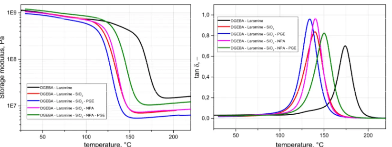
The studied nanocomposites were characterized using DMA and TGA. The elastic modulus, Tg, and thermal stability (temperature T3) were determined. Fig. 7 shows the dynamic mechanical analysis results for the nano-composites, i.e., the temperature dependence of the shear modulus, G’, and the mechanical loss factor, tan δ (G“/G’). Table 4. Thermomechanical properties and thermal stability
of the epoxy matrix and nanocomposites
Sample Tg (°C) G (MPA)
at 200 °C T3 (°C)
DGEBA – L. 174 15.0 334
DGEBA – L. - SiO2 140 7.9 347
DGEBA – L. - SiO2 - PGE 134 6.2 325
DGEBA – L. - SiO2 - NPA 140 8.1 329
DGEBA – L. - SiO2 - PGE - NPA 150 11.4 318
Fig. 7. The shear modulus, G’, and mechanical loss factor, tan δ (G“/G’), with respect to temperature
A summary of the results is given in Table 4.
The incorporation of silica into the epoxy matrix results in a decrease in the Tg and modulus. Hydrophobic modified silica acts in the matrix as a plasticizer, which is a consequence of the weak interfacial epoxy-silica (hydrophobic) interactions and an enlarged free volume [41], allowing for greater mobility of chains (see [42] for a hypothesis on the involvement of the Ds declining free
volume theory). Application of reactive diluent PGE in the preparation of nanocomposites causes a decrease in the Tg and modulus, as a substitution of diepoxide for mono-functional epoxide PGE causes a decrease in the network crosslinking density.
This deterioration of the thermomechanical properties of nanocomposites is partly compensated by the use of nanofibrous NPA. The TGA curves characterizing the mass loss of the material when heated in an air atmosphere are shown in Fig. 8. From Fig. 8 and Table 4, the silica clearly increases the thermal stability of the material in comparison with the epoxy matrix, whereas NPA and PGE reduce it.
The nanocomposite containing silica and NPA (the best from an electric point of view) had suitable thermal properties for thermal class F but had a small decrease in the Tg and modulus compared with those of the epoxy matrix. Future experiments should focus on mechanical improvement of the material.
5. Conclusion
A DGEBA Cycloaliphatic Diamine Nano PA and SiO2
composite was prepared as an alternative to conventional electrical insulation systems containing macroscopic inorganic components. The proposed material should exhibit similar or improved dielectric and thermal properties. The prepared composite exhibits the following electrical properties: volume resistivity on the order of 1016 Ω·m, dissipation factor tan δ = 4.7·10-3, and dielectric strength 39 kV/mm (example parameters of conventional EIS materials for resin rich technology [main wall insulation of rotary machines]: internal resistivity ρv of
1013 Ω·m, dissipation factor tan δ = 0.015 and dielectric strength of Ds = 35 kV/mm). The thermal class of the
material is the same as that of the conventional – F (155°C). The Tg of the composite is worse, as expected (173°C vs 140°C), compared with that of the matrix. The Tg was reduced by the addition of nanoparticles in, e.g., [35] and Table 4; therefore, we used resin with high Tg. The problem here is different from that of conventional materials with macro inorganic components in which the matrix is the weak point of the system (resin, glass, mica). In our case, the lowest Tg of the system had NPA.
The resulting material exhibits good thermal stability, as shown Fig. 8, and the material is stable up to approx. 300°C.
The system comprises a combination of two types of nanofillers, hydrophobic silica nanoparticles and nano-fibrous polyamide 6. The inner structure is more homogenous, meaning a better inner distribution of the electrical field. Therefore, we expect lowered inner PD activity, which is to be proven by a long-term electrical aging test.
We showed that an NPA nano nonwoven layer can act as a dielectric barrier (for high-voltage use of the material) that can replace mica with a resulting dielectric strength of 39 kV/mm. Hydrophobic silica increases the volume resistivity to approximately 5·1016 Ω·m. The resulting dielectric loss, tan δ, of approximately 0.005 at temperatures up to 100 °C is also suitable. Hydrophobic silica increases the thermal stability of the material. Overall, the thermomechanical properties and thermal stability of nanocomposites are slightly deteriorated by incorporation of nanofillers compared to those of the epoxy matrix, as a compromise between high dielectric strength for high-voltage purposes. In EIS systems such as the one proposed, a high Tg of the matrix is required.
The complex DGEBA – Laromine – Hydrophobic SiO2
– NPA nanocomposite has some improved properties compared with conventional electrical insulation materials. It is an electrical insulating system without an inorganic (mica) dielectric barrier, which is beneficial, and therefore, it is undoubtedly a novel material.
Further research must to be done to explain the role of the nanoparticles in the electric breakdown process [41, 42]. To replace the conventional material with a carrier (e.g., glass fabric), it is necessary to improve the tensile strength of the proposed material.
Acknowledgements
This work is supported by the Ministry of Education, Youth and Sports of the Czech Republic under the RICE — New Technologies and Concepts for Smart Industrial Systems, project No.LO1607 and by the Student Grant Agency of the West Bohemia University in Pilsen, grant No. SGS-2018-016 Diagnostics and materials in electrotechnics.
References
[1] R. Brütsch, M. Tari, K. Fröhlich, T. Weiers, R. Vogelsang, “Insulation failure mechanisms of power generators,” IEEE Elect. Insul. Mag., vol. 24, no. 4, pp. 17-25, Jul.-Aug. 2008.
[2] C. M. Laffoon, C. F. Hill, G. Lee Moses, L. J. Berberich, “A new high-voltage insulation for turbine-generator stator windings,” Trans. Am. Inst. Electr. Eng., vol. 70, no. 1, pp. 721-730, Jul. 1951.
[3] B. Dewimille and A.R. Bunsell, “Accelerated ageing of a glass fibre-reinforced epoxy resin in water,”
Composites, vol. 14, no. 1, pp. 35-40, Jan. 1983. [4] G. C. Stone, I. Culbert, E A. Boulter, H. Dhirani,
“Electrical Insulation for Rotating Machines:Design, Evaluation, Aging, Testing, and Repair,” Wiley-IEEE Press: Piscataway, 2014, pp. 111-131.
[5] R. L. Griffeth, E. R. Younglove, “The manufacture and processing of mica paper for use in electrical insulation,” in Proc. COI, 1951, pp. 22-23.
[6] N. Andraschek, A. J. Wanner, C. Ebner, G. Riess, “Mica/epoxy-composites in the electrical industry: applications, composites for insulation, and investi-gations on failure mechanisms for prospective optimizations,” Polymers, vol. 8, pp. 1-21, Aug. 2016. [7] Z. Jia, Y. Hao, H. Xie, “The degradation assessment
of epoxy/mica insulation under multi-stresses aging,” in IEEE Trans. Dielectr. Electr. Insul., vol. 13, no. 2, pp. 415-422, Apr. 2006.
[8] R. Goetter. M. Winkeler, “New developments in unsaturated polyester resins used for electrical insulation,” in Proc. EEIC, 2001, pp. 51-56.
[9] G. H. Miller, “Silicone resin rich mica paper laminates for class H operation and radiation resistance,” in Proc. EIC, 1975, pp. 273-275.
[10] L. Harvanek, “Nanomaterials for electrotechnic,” Doctoral Dissertation, University of West Bohemia, Pilsen, 2017.
[11] V. Boucher, P. Rain, G. Teissedre, P. Schlupp, “Mechanical and dielectric properties of glass-mica-epoxy composites along accelerated thermo-oxidative aging,” in Proc. ICSD, 2007, pp. 162-165.
[12] International Electrotechnical Commission, “Electrical Insulation - Thermal Evaluation and Designation” IEC Standard 60085:2007, Nov. 7, 2007.
[13] J. Dong, Z. Shao, Y. Wang, Z. Lv, X. Wang, K. Wu, We. Li, C. Zhang, “Effect of temperature gradient on space charge behavior in epoxy resin and its nano-composites,” IEEE Trans. Dielectr. Electr. Insul., vol. 24, no. 3, pp. 1537-1546, Jun. 2017.
[14] D. R. Johnston, M. Markovitz, “Corona-resistant insulation, electrical conductors covered therewith and dynamoelectric machines and transformers incorporating components of such insulated con-ductors,” US Patent 4760296, Jul. 26, 1988.
[15] P. O. Henk, T. W. Korsten, T. Kvarts, “Increasing the electrical discharge endurance of acid anhydride cured DGEBA epoxy resin by dispersion of nano-particle silica,” High Perform. Polym. vol. 11, no. 3, pp. 281-296, Sept. 1999.
[16] T. G. Lewis, “Nanometric dielectrics,” IEEE Trans. Dielectr. Electr. Insul.. vol. 1, no. 5, pp. 812-825, Oct. 1994.
[17] J. K. Nelson, J. Fothergill, L. A. Dissado, W. Peasgood, “Towards an understanding of nanometric dielectrics,” in Proc. CEIDP, 2002, pp. 295-298. [18] T. Tanaka, T. Imai, “Advances in nanodielectric
materials over the past 50 years,” IEEE Elect. Insul.
Mag., vol. 29, no. 1, pp. 10-23, Jan.-Feb. 2013. [19] S. Yu, P. Hing, “Thermal and dielectric properties of
fiber reinforced polystyrene composites,” Polym. Compos., vol. 29, no. 11, pp. 1199-1202, Nov. 2008. [20] G. G. Raju, “Dielectrics in Electric Fields,” Boca
Raton: CRC Press, Taylor & Francis Group, 2016. [21] R. Stewart, “Thermoplastic composites — recyclable
and fast to process,” Reinf. Plast., vol. 55, no. 3, pp. 22-28, May-Jun. 2011.
[22] R. B. Valapa, S. Loganathan, G. Pugazhenthi, S. Thomas, T.O. Varghese. “An overview of polymer– clay nanocomposites,” Clay-Polymer Nanocomposites. Amsterdam: Elsevier. pp. 29-81, 2017.
[23] A. C. Biju, T. A. A. Victoire, D. E. Salvaraj, “Enhancement of dielectric properties of polyamide enamel insulation in high voltage apparatuses used in medical electronics by adding nano composites of SiO2 and Al2O3 fillers,” J. Electr. Eng. Technol., vol.
10, no. 4, Jul. 2015.
[24] S. K. Singh, S. Sing, A. Kumar, A. Jain, “Thermo-mechanical behavior of TiO2 dispersed epoxy
composites,” Eng. Fract. Mech., vol. 184, pp. 241-248, Oct. 2017.
[25] N. Loganathan, S. Chandrasekar, “Analysis of surface tracking of micro and nano size alumina filled silicone rubber for high voltage AC transmission,” J. Electr. Eng. Technol., vol. 8, no. 2, Mar. 2013. [26] W. Yang. R. Yi, X. Yang, M. Xu, S. Hui, X. Cao,
“Effect of particle size and dispersion on dielectric properties in ZnO/epoxy resin composites,” Trans. Electr. Electron. Mater., vol. 13, no. 3, pp. 116-120, Jun, 2012.
[27] T. Andritsch, R. Kochetov, P. H. F. Morshuis, J. J. Smit, “Dielectric properties and space charge behavior of MgO-epoxy nanocomposites,” in Proc. ICSD, 2010, pp. 1-4.
[28] I. A. Tsekmes, R. Kochetov, P. H. F. Morshuis, J. J. Smit, “AC breakdown strength of epoxy-boron nitride nanocomposites: Trend & reproducibility,” in Proc. EIC, 2015, pp. 446-449.
[29] J. Boček, L. Matějka, V. Mentlík, P. Trnka, M. Šlouf, “Electrical and thermomechanical properties of epoxy-POSS nanocomposites,” Eur. Polym. J., vol. 47, no. 5, May 2011.
[30] A. S. Vaughan, G. Gherbaz, S. G. Swingler, N. A. Rashid, “Polar/non-polar polymer blends: on structural evolution and the electrical properties of blends of polyethylene and ethylene - vinyl acetate,” in Proc. CEIDP, 2006, pp. 272-275.
[31] K. Nam, J. Cho, H. Yeo, “Thermomechanical behavior of polymer composites based on edge-eselectively functionalized graphene nanosheets”. Polymers, vol 10, no. 1. pp. 1-11, Jan. 2018.
[32] M. Liang, K. L. Wong, “Study of mechanical and thermal performances of epoxy resin filled with micro particles and nanoparticles,” Energy Procedia,
vol. 110, pp. 156-161, March 2017.
[33] M. H. Alaei, P. Mahajan, M. Brieu, D. Kondo, S. J. A. Rizvi, S. Kumar, N. Bhatnagar, “Effect of particle size on thermomechanical properties of particulate polymer composite,” Iran. Polym. J., vol. 22, n. 11, pp. 853-863. Nov. 2013.
[34] G. Liu, G. H. Zhang, D. Zhang, Z. Zhang, X. An, X. Yi, „On depression of glass transition temperature of epoxy nanocomposites,” J. Mater. Sci., vol. 47, no. 19, pp. 6891-6895, Oct. 2012.
[35] C. Zou, J. C. Fothergill, S. W. Rowe, “The effect of water absorption on the dielectric properties of epoxy nanocomposites,” IEEE Trans. Dielectr. Electr. Insul., vol. 15, no. 1, pp. 106-117, Feb. 2008.
[36] E. Marsano, L. Francis, F. Giunco, “Polyamide 6 nanofibrous nonwovens via electrospinning,” J. Appl. Polym. Sci., vol. 117, no. 3, pp. 1754-1765, Aug. 2010. [37] International Electrotechnical Commission, “Dielectric and resistive properties of solid insulating materials - Part 3-2: Determination of resistive properties (DC methods),” IEC Standard 62631-3-2:2015, Apr. 12, 2015.
[38] International Electrotechnical Commission, “Recom-mended methods for the determination of the permittivity and dielectric dissipation factor of electrical insulating materials at power, audio and radio frequencies including metre wavelengths,” IEC Standard 60250:1969, Jan. 1, 1969.
[39] International Electrotechnical Commission, “Methods of test for electric strength of solid insulating materials,” IEC Standard 60243-1, Mar. 26, 2013. [40] V.I. Ushakov, “Insulation of High-Voltage Equipment,”
New York: Springer, 2004, pp. 11-15.
[41] J. Artbauer, “Electric strength of polymers,” J. Phys. D., vol. 29, no. 2, pp. 446-56, Feb. 1996.
[42] J. K. Nelson, Y. Huang, T.M. Krentz, L. S. Schadler, J. Dryzek, B. C. Benicewicz, M. Bell, “Free volume in nanodielectrics,” in Proc. ICPADM, 2015, pp. 40-43.
Pavel Trnka He was received the MSc and PhD degrees from the University of West Bohemia, Czech Republic, in 2002 and 2005, respectively. He was a student of the University of Applied Science, Fachhochschule, Regensburg, Germany, and worked at the Depart-ment of Research, Maschienenenfabrik Reinhausen, Germany, in 2003-4. During 2006 to 2007 he was a postdoctoral associate in the High Voltage Laboratory, Department of Electrical and Computer Engineering, Mississippi State University, USA. In 2008 he graduated dr. hab. University of Zilina, Faculty of Electrical Engineering, Slovakia.
Vaclav Mentlík He was born in Pilsen in 1939. He graduated from the School of Mechanical and Electrical Engine-ering in Pilsen and later worked at Faculty of Electrical Engineering, University of West Bohemia in Pilsen. In 1985, he recieved a PhD in 1998, he became professor in the field of Electrotechnology. He is head of section of Electro-technolgy at FEE UWB in Pilsen. He successfully led 23 projects and was supervisor of 25 PhD. He was awarded twice by the Prize of University of West Bohemia.
Lukas Harvanek He was born in Klatovy in 1988. He received the MSc and PhD degree from the University of West Bohemia, Czech Republic in 2012. He was a student of the Brunel University, Institute of Power Systems, London, England in 2012 - 2013 and also a student of Beijing Institute of Technology, Beijing, China in 2015.
Jaroslav Hornak He was born in Klatovy in 1989. He received the MSc degree from the University of West Bohemia, Czech Republic in 2014. He completed a traineeship at P&G Rakona, Rakovník, Czech Republic in 2016 and also practical internship at University of Zilina, Faculty of Electrical Engine-ering, Zilina, Slovakia in 2017.
Libor Matejka He was born in Prague in 1947. He graduated at Charles University in Prague and then he has been working in the Institute of Macromolecular Chemistry in Prague. Here he received PhD in 1977 and in 2009 he became Doctor of Science (DSc.). Since 1994, he has been a head of Department of Nanostructured Polymers and Composites, and since 2010 he is a head of Scientific Centre of Polymer Materials and Technologies. He was awarded two times (1981 and 2010) by the Prize of Academy of Sciences of the Czech Republic.