A Study on Image Based Visual Tracking for SCARA Robot
Hang Bong Shin*, Hong Rae Kim*, Dong Yean Jung**, Byeong Chang Kim*** and Sung Hyun Han*** * Division of Mechanical and Automation Eng., Kyungnam University, Masan, Gyeongnam, 631-701, Korea
** DAEHO Technology Korea, 61-1, Palyong-dong, Changwon, Gyeongnam, 641-465, Korea *** Dept. of Mechanical Design, Graduate School, Kyungnam University, Masan, Gyeongnam, 631-701, Korea
(Tel : +82-55-249-2624; E-mail: [email protected])
Abstract: This paper presents how it is effective to use many features for improving the speed and the accuracy of the visual servo
systems. Some rank conditions which relate the image Jacobian and the control performance are derived. It is also proven that the accuracy is improved by increasing the number of features. Effectiveness of the redundant features is evaluated by the smallest singular value of the image Jacobian which is closely related to the accuracy with respect to the world coordinate system. Usefulness of the redundant features is verified by the real time experiments on a Dual-Arm Robot manipulator made in Samsung Electronic Co. Ltd
Keywords: SCARA Robot, Visual Tracking, Image Jacobian
1. INTRODUCTION
Many of the control and vision problems are similar to those encountered by active vision researchers who are building "robotic heads". However the task in visual servoing is to control a robot to manipulate its environment using vision as opposed to just observing the environment.
There are mainly two ways to put the visual feedback into practice. One is called look-and-move and the other is visual servoing. Visual servoing is the fusion of results from many elemental areas including high-speed image processing, kinematics, dynamics, control theory, and real-time computing. It has much in common with research into active vision and structure from motion, but is quite different from the often described use of vision in hierarchical task-level robot control systems. The former is the method which transforms the position and orientation of an object obtained by a visual sensor into those in the world frame fixed to an environment and guides the arm of the manipulator to a desired location in the world frame.[1-2] In this method, precise calibration of a manipulator and camera system is needed. On the contrary, visual servoing uses the Jacobian matrix which relates the displacement of an image feature to the displacement of a camera motion and performs a closed-loop control regarding the feature as a scale of the state. Therefore, we can construct a servo system based only on the image and can have a robust control against the calibration error because there is no need to calculate the corresponding location in the world frame.[2-4] A hand eye system is often used in visual feedback and there are two ways of arranging the system. One is placing a camera and a manipulator separately; the other is placing the camera at the end-tip of the manipulator. The former motion strategy of the manipulator becomes more complicated than the latter. In the latter, it is easy to control the manipulator using a visual information because the camera is mounted on the manipulator end-tip. In this paper, we deal with the latter method. In the conventional works, some researches have presented methods to control the manipulator position with respect to the object or to track the feature points on an object using a hand eye system as the application of visual servoing.[3-4] These methods maintain or accomplish a desired relative position between the camera and the object by monitoring feature points on the object from the camera.[5-6]
However, these have been all done by the hand eye system with monocular visions and it is necessary to compensate for
the loss of information because the original three-dimensional information of the scene is reduced to two-dimension information on the image. For instance, we must add an information of the three-dimension distance between the feature point and the camera in advance or use a model of object stored in the memory. Besides, a problem that the manipulator position fails to converge to a desired value arises depending on the way of selecting feature points or when the initial positioning error is not small. It is because some elements of the image Jacobian cannot be computed with only the information of the image and substituting approximate values at the desired location for them may result in large errors at the other locations.[7-8]
This paper presents a method to solve this problem by using a binocular stereo vision. The use of stereo vision can lead to an exact image Jacobian not only at around a desired location but also at the other locations. The suggested technique places a robot manipulator to the desired location without giving such priori knowledge as the relative distance to the desired location or the model of an object even if the initial positioning error is large.
This paper deals with modeling of stereo vision and how to generate feedback commands. The performance of the proposed visual servoing system was evaluated by the simulations and experiments and obtained results were compared with the conventional case for a SCARA type dual-arm robot.
2. VISUAL SERVO SYSTEM
Visual servo systems typically use one of two camera configurations: end-effector mounted, or fixed in the workspace.
The first, often called an eye-in-hand configuration, has the camera mounted on the robot's end-effector. Here, there exists a known, often constant, relationship between the pose of the camera(s) and the pose of the end-effector.
We define the frame of a hand-eye system with the stereo vision and use a standard model of the stereo camera whose optical axes are set parallel each other and perpendicular to the baseline. The focal points of two cameras are apart at distance d on the baseline and the origin of the camera frame ∑c is located at the center of these cameras.
An image plane is orthogonal to the optical axis and apart at distance f from the focal point of a camera and the origins of
frame of the left and right images, ∑l and ∑r, are located at the intersecting point of the two optical axes and the image planes. The origin of the world frame ∑w is located at a certain point in the world.
Now let l
p
=
(
lx
,
ly
)
and rp
=
(
rx
,
ry
)
be the projections onto the left and right images of a pointp
in the environment, which is expressed as cp
=
(
cx
cy
cz
)
T in the camera frame. Then the following equation is obtained (see Fig. 1).Suppose that the stereo correspondence of feature points between the left and right images are found. In the visual servoing, we need to know the precise relation between the moving velocity of camera and the velocity of feature points in the image, because we generate a feedback command of the manipulator based on the velocity of feature points in the image.
)
5
.
0
(
x
d
f
z
x
c c l=
+
)
5
.
0
(
x
d
f
z
x
c c r=
−
(1)y
f
z
y
c c l=
y
f
z
y
c c r=
This relation can be expressed in a matrix form which is called the image Jacobian. Let us consider n feature points
) , , 1
(k n
pk = L on the object and the coordinates in the left and right images are lpk(lxk,lyk) and rpk(rxk,ryk) , respectively. Also define the current location of the feature points in the image Ip as
T n r n l n r n l r l r l I
p
(
x
x
y
y
x
x
y
y
)
1 1 1 1L
=
(2)where each element is expressed with respect to the virtual image frame
∑
p.First, to make it simple, let us consider a case when the number of the feature points is one. The relation between the velocity of feature point in image Ip
&
and the velocity of camera frame cp&
is given asp
J
p
c c I I&
&
=
(3) where IJc is the Jacobian matrix which relates the two frames. Now let the translational velocity components of camera bex
σ
,σ
y andσ
z and the rotational velocity components bex
w ,wy, wz then we can express the camera velocity V as
T c c c T z y x z y x
w
v
w
w
w
V
]
[
]
[
=
=
σ
σ
σ
(4)Then the velocity of the feature point seen from the camera frame cp
&
can be written) ( } ) ( { ) ( c w W w c c w W c w w c c w w w c c c p p R p p w R p p R dt d dt p d p & & & − + − × − = − = = (5)
Where cRw is the rotation matrix from the camera frame to the world frame and wpc is the location of the origin of the camera frame written in the world frame. As the object is assumed to be fixed into the world frame, wp&=0. The relation between cp& and V is
− + − − + − − + − = − × − = − − × − = z c y c x y c x c z x c z c y c c c c c c w w c c w w c w w c c v x w y w v z w x w v y w z w p p w p R p p w R p & & & { ( )} (6)
Therefore, substituting Eq. (6) into Eq. (3), we have the following equation. V J p J p I c c I = = & & (7)
In Eq. (7) matrix J which expresses the relation between velocity Ip& of the feature point in the image and moving velocity V of the camera is called the image jacobian.
From the model of the stereo vision Eq. (1), the following equation can be obtained.
) ( ) ( 2cx lx− rx =d lx+ rx (8) d y d y x x y l r l r c ( − )= = (9) d f x x z l r c ( − )= (10)
Above discussion is based on the case of one feature point. In practical situation, however, the visual servoing is realized by using plural feature points. When we use n feature points, image Jacobian J1,L,Jn are given from the coordinates of feature points in the image. By combining them, we express the image Jacobian (Jim) as
T n
im J J
J =[ 1LL ] (11) Then, it is possible to express the relation of the moving velocity of the camera and the velocity of the feature points even in the case of plural feature points, that is,
Ip& = JimV (12) where we suppose that the stereo and temporal correspondence of the feature points are found.
In the case of the monocular, the image Jacobian J has the following form.
Fig. 1 The coordinates system of vision model − − + − + − − = z x x y x z y x y x z y x x z y x x x x f J c c c c c c c c c c c c c c c c c c c c 2 2 2 2 2 2 2 1 1 0 1 0 1 (13)
The x, y and z axes of the coordinate frames are shown in Fig. 1.
We now introduce the positional vector of the feature point in the image of monocular vision using the symbol
) , ( x y
P m m
m = . This is the projection of the point expressed as T
c c c
cP=( x y z) in the camera frame into the image frame of
the monocular vision, and has the following relation.
1 − = f x z x c c m (14-a) 1 − = f y z y c c m (14-b)
Substituting Eq.s (14-a) and (14-b) into Eq. (13) yields another expression of the image Jacobian for the monocular vision. − − + + − + − − = x f y x f f y x y x f y f f x f y x x x z f J m m m m c m c m m m m c m c 2 2 2 2 2 2 1 0 0 1 (15)
A disparity which corresponds to the depth of the feature point, is included in J in the case of the stereo vision, but s-term expressed in the camera frame cz is included in J in the case of the monocular vision.
In the visual servoing, the manipulator is controlled so that the feature points in the image reach their respective desired locations.
We define an error function between the current location of the feature points in image Ip and the desired location
d Ip
as
E=Q(Ip− Ipd) (16) where Q is a matrix which stabilizes the system. Then the feedback law is defined as following equation
V =−G E (17) where G corresponds to a feedback gain.
To realize the visual servoing, we must choose Q so that convergence is satisfied with the error system can be satisfied with E GQJ V QJ P Q t p Q t E E im im I I − = = = ∂ ∂ = ∂ ∂ = & & & (18)
Fig. 2 Block diagram of visual feedback system.
We use pseudo-inverse matrix of the image Jacobian Jim for Q to make QJim positive and not to make an input extremely large, that is,
T im im T im im J J J J Q= + =( )−1 (19) Therefore, the feedback command is given as
) ( d I I im p p J G V =− + − (20) Fig. 2 shows a block diagram of the control scheme described by Eq. (20). Note that the feedback command u is sent to the robot controller and both the transformation of u to the desired velocity of each joint angle q&d and its velocity servo are accomplished in the robot controller as show in Fig. 2. Furthermore, as Jim is a 4n×6 matrix and pseudo-inverse matrix Jim+ is a 6×4n matrix, a feedback command Eq. (20) of 6 degrees of freedom is obtained.
3. EXPERIMENTS
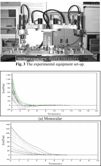
We have compared the visual servoing using the monocular vision with that using the stereo vision by the experiment. Fig. 3 represents the experimental equipment set-up. In Fig. 3 two DSP vision boards were used, which had been made Samsung Electronics Company in Korea based-on the TMS320C31 chips. In the experiment, feature points of an object are the four corners of a square whose side dimension is 300mm. In the same condition, we used four feature points even in the stereo vision. Parameters used the focal length, f =16mm, baseline
mm
d 130= , sampling time of 50 msec , gain
λ
=1,desired location P Tmm
d
c =(100100500) , desired
orientation in Euler angle (
φ
,θ
,ψ
)=(0,0,0)rad, initial errorT ) 50 , 50 , 50
rad ) 20 , 20 , 20 ( ) , , (
φ
θ
ψ
= in the orientation.We select the four corners of a rectangle whose size is mm
200
200× as the feature points and set the translational error as (−150−150−450)mm and the other values are the same as before.
The error between the desired location and the current location of the feature points in cases of the monocular and stereo visions are shown in Fig. 4.
Next, we will show the results for the change of the way to choose the feature points and set the initial error image.
In Fig. 4, we can see that the result diverges in the case of the monocular vision, but converges in the case of the stereo vision. This is because the image Jacobian is fixed at the desired location in case of the monocular vision. Therefore, a correct feedback command can not be generated when the initial error is large. On the other hand, the image Jacobian can be updated at every in the case of the stereo vision, thus it is possible to generate a correct feedback command which assures the stability visual servoing.
In experiments, we used a SCARA type dual-arm robot made in Korea with a stereo camera attached to the end tip of the arm. The feature points are three circular planes of 20mm radius on three corners of a equilateral triangle, one side
mm
87 and are placed on the board. Precise calibration had not been done for the stereo camera attached to the end-tips.
Fig. 3 The experimental equipment set-up.
(a) Monocular
(b) Stereo
Fig. 4 Positional error in x and y axes in the case of the stereo and monocular vision.
(a) Left image
(b) Right image
Fig. 5 Position error in x and y axes.
Two stereo images were taken and transformed to the binary images in the real time and in parallel by two image input devices and the coordinate of the gravitational center of each feature point was calculated in parallel by two transporters. We gave the stereo correspondence of the feature point in the first sampling. However, the stereo and temporal correspondence of the feature points in the succeeding sampling were found automatically by searching a nearby area where there were the feature points in the previous sampling frame. The coordinates of the feature points were sent to a transporter for motion control and it calculated a feedback command for the robot. The result was sent to the robot controller by using RS-232C, and the robot was controlled by a velocity servo system in the controller.
The sampling period of visual servoing was about 50 msec. Details were 16 msec for taking a stereo images, about
sec
1m for calculating the coordinates of the feature points, sec
3m for calculating feedback command, about 16 msec for communicating with the robot controller. If we send a feedback input to the robot controller without using RS-232C, the faster visual servoing can be realized.
The desired location was (0,0,500)Tmm and the desired orientation in Euler angle, (
φ
,θ
,ψ
)=(0,0,0) degree and the initial error was (50,50,50)Tmm for translation. The other parameters were the same as in the simulation. The error of current and desired location of the feature points are shown in Fig. 5. From these experimental results, we can see that the manipulator converges toward a desired location even if the calibration is not precise.4. CONCLUSION
We proposed a new technique of visual servoing with the stereo vision to control the position and orientation of an assembling robot with respect to an object. The method overcomes the several problems associated with the visual servoing with the monocular vision. By using the stereo vision,
the image Jacobian can be calculated at any position. So neither shape information nor desired distance of the target object is required. Also the stability of visual servoing is assured even when the initial error is very large. We have shown the effectiveness of this method by simulation and experiments.
To use this visual servoing in practical tasks, there still exist many problems such as the number of feature points to reduce noise or the quantization error and the way to choose feature points. Nevertheless, this method overcomes the several problems in visual servoing with the monocular vision.
ACKNOWLEDGEMENTS
This research was supported by the New University for Regional
Innovation program of the Ministry of Education & Human
Resources Development (NURI MECHANO 21).
REFRENCE
[1] Hashimoto, K., Edbine, T., and Kimura, H., "Dynamic visual feedback control for a hand-eye manipulator". In Proceedings of the IEEE/RSJ International Conference on Intelligent Robots and Systems, pp. 1863-1868, 1992.
[2] Bernard, E., Francois, C., and Patrick, R., "A new approach to visual servoing in robotics". IEEE Transactions on Robotics and Automation, pp. 313-326, 1992.
[3] Weiss, L. E., Sanderson, A. C., and Neuman, C. P., "Dynamic sensor-based control of robots with visual feedback". IEEE Journal of Robotics and Automation, pp. 404-417, 1987.
[4] G. Hager, S. Hutchinson, and P. I. Corke. "A tutorial on visual servo control". IEEE Trans. Robotics & Automation, Vol. 12, No. 5, pp. 651-670, 1996.
[5] V. Sundareswaran, P. Bouthemy, and F. Chaumette. "Exploiting image motion for active vision in a visual servoing framework". International Journal of Robotics Research. Vol. 15, No. 6, pp. 629-645, 1996.
[6] Allen, P. K., Toshimi, B., Timcenko, A., "Real Time Visual Servoing". In Proceeding of the IEEE International Conference on Robotics and Automation, pp. 851-856, 1991.
[7] Hashimoto, K., Kimoto, T. Edbine, T., and Kimura, H., "Manipulator control with image-based visual servo". In Proceedings of IEEE International Conference on Robotics and Automation, pp. 2267-2272, 1991.
[8] Chaumette, F., Rives, P., and Espiau, B., "Positioning of a robot with respoect to an object, tracking it and estimating its velocity by visual servoing". In Proceedings of the IEEE International Conference on Robotics and Automation, pp. 2248-2253, 1991.