1. INTRODUCTION
Replacement of existing worn-out or obsolete analog control systems has been considered. Replacement of existing analog control systems with another analog control systems has lots of difficulties in maintaining the systems due to being out of stock. Due to those difficulties, existing analog control systems have been retrofitted with digital DCSs in many industrial sites. KEPRI(Korea Electric Power Research Institute) accomplished the project that retrofitted analog control systems with the developed DCSs for boiler unit in middle-scale coal-fired thermal power plant. The benefits of an upgrade to digital control include a increase of reliability due to system redundancy, ease of modifying the control logic and the parameters of function block, ease of maintenance due to available spare parts, improvement of information display, ease of modifying MMI(Man Machine Interface) displays, a increase in system availability, and improvement of control performance.
Most commercial controllers that are used in large-scale plant such as power plant are PID(Proportional Integral Derivative) controllers, and PI controllers are adopted in most of the control loops except temperature control loop. Controller tuning is time-consuming, and requires many trial-and-errors. When it is considered to retrofit analog control system with digital control system, use of controller parameters of existing analog controllers is helpful to fine-tune the controller parameters during commissioning.
This paper describes power plant overview, how to use the parameters of existing analog controllers, the implementation of digital PID controller, digital control system configuration for boiler unit in thermal power plant, feedwater control loop, control result during commissioning, and the comparison of boiler characteristic test data after retrofitting with the existing test data.
2. POWER PLANT OVERVIEW
The overview of the middle-scale coal-fired power plant that retrofitting is applied to in this paper is shown in Fig. 1, and the specification is as follows :
- Maximum Power : 250 MW
- Maximum Steam Evaporation : 875 Ton/hr(in case that oil is fired), 600 ~ 800 Ton/hr(in case that coal is fired, it depends on coal type)
- Steam Pressure : 169 kg/cm2 - Steam Temperature : 541 oC
- Boiler type : natural circulation boiler - Combustion mode : coal-fired/oil-fired - Boiler draft : balanced draft
- Existing boiler control system : Bailey 820 System - Existing Mill Burner Control System : N.F.K system
Fig. 1 Power plant overview
In the natural circulation boiler, the feedwater pump
forces the water through the economizer into the drum. From there it is supplied to the lower furnace wall headers through a system of mostly unheated downcomer tubes. Steam is generated as the water rises through the furnace wall riser tubes exposed to heat radiation. The water/steam mixture is then transferred to the boiler drum. The circulation is maintained by the difference in the densities in the downcomers and in the risers, and is evidently caused by gravitation. Steam is separated from the steam/water mixture in the drum, and leaves the boiler through the superheater section [1].Retrofit of Analog Boiler Control Systems with Digital Control Systems
in a Thermal Power Plant
Doo-Yong Park, Seung-Hyun Byun
Power Generaton Laboratory, KEPRI, Daejeon, Korea (Tel : +82-42-865-5376; E-mail: [email protected])Abstract: This paper presents the case that the existing analog control systems were retrofitted with digital DCS(Distributed
Control System)s for boiler unit in thermal power plant. Replacement of existing worn-out or obsolete analog control systems has been considered. Replacement of existing analog control systems with another analog control systems has lots of difficulties in maintaining the systems due to being out of stock. Due to those difficulties, existing analog control systems have been retrofitted with digital DCSs in many industrial sites. KEPRI(Korea Electric Power Research Institute) accomplished the project that retrofitted analog control systems with the developed DCSs for boiler unit in middle-scale coal-fired thermal power plant. The benefits of an upgrade to digital control include a increase of reliability due to system redundancy, ease of modifying the control logic and the parameters of function block, ease of maintenance due to available spare parts, improvement of information display, ease of modifying MMI(Man Machine Interface) displays, a increase in system availability, and improvement of control performance. This paper describes how to use the parameters of existing analog controllers, the implementation of digital PID controller, control system configuration for boiler unit in thermal power plant, some boiler control loops, control result during commissioning, and the comparison of boiler characteristic test data after retrofitting with the existing test data.
3. DIGITAL CONTROL SYSTEM
3.1 Control System Configuration
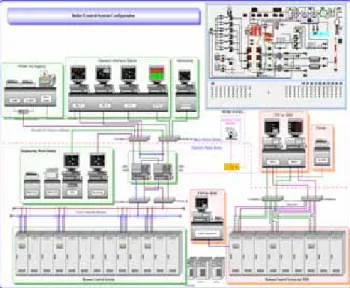
The configuration of digital boiler control systems applied to a middle-scale coal-fired thermal power plant is shown in Fig. 2 [2]. I/O points and control panels are allocated to be compatible with existing control system and reuse existing wire. Boiler control systems are largely composed of automatic boiler control (ABC) system and burner management system (BMS). ABC system is composed of boiler main control system that controls main boiler system, alarm system that announces process alarms, auxiliary control system that controls auxiliary boiler system. BMS system handles MFT (Master Fuel Trip)-related logic, furnace purge, Fan start/stop, coal feeder, pulverizer, burner control and so on. ABC system is composed of 4 stations and 13 panels, while MBC system is composed of 3 stations and 9 panels. The number of I/O points that ABC system and BMS system can handle is listed in Table 1.
Fig. 2 Digital boiler control system configuration Table 1 The number of I/O points in boiler control systems
AI AO DI DO Total
ABC 804 260 912 423 2,399
BMS - - 1527 1260 2,787
Total 804 260 2,439 1,683 5,186 ABC system is composed of remote control station (RCS), data processing station, engineering work station (EWS), operator interface system (OIS) as shown in Fig 2. RCS is largely composed of main processing unit (MPU) shelf for main control, I/O shelf for I/O processing. MPU shelf has system redundancy and is composed of system power supply, MPU board for main control, data interface unit (DIU) for intermediate data and control processing, field bus controller (FBC) for communication with data control unit (DCU) of I/O shelf, and network interface controller (NIC) for communication with other RCS, and data link unit (DLU) for system redundancy. I/O shelf is composed of DCU board for communication with MPU shelf, analog I/O board, digital I/O board and power supply. Data processing station manages and processes data via database.
3.2 Existing PI controller
Existing PI controller is summer + bias + proportional +
integral unit shown in Fig. 3. Proportional gain and integral time are adjusted via face plate. This unit is a combination of summer + bias circuit and proportional + integral circuit, and the output of summer + bias is used as the input to proportional + integral circuit. In Fig. 3, IC U1 is the driving amplifier for summer + bias module, and the inputs are applied to amplifier U1 via connector pin 1 ~ 4. The output of summer at output pin 12 is given by
] 2 [ 4 6 5 8 3 4 3 8 2 2 8 1 1 8 12 E Ebias R R R E R R R E R R E R R E + + + + + + − = (1)
where E1~E4 are voltages applied to pin1~4 respectively, and
Ebias is bias input.
Fig. 3 Circuit of summer + bias + proportional + integral unit The summer + bias circuit is used to compute error that is the input to PI controller using set value and process value, which are applied to input E1 and E2 respectively. The output of summer is applied to the input of proportional + integral module. The output of PI module at output pin 7 is given by
] 1 ) 1 1 ( [ 12 35 / 21 12 16 15 21 14 13 13 7
∫
+ + + + + − ≈ dt E C R R R E R R R R R R E MIN REP(2)
Eq. (2) is the form of the ideal PI algorithm. Therefore, Eq. (2) is rewritten by ] ) ( ) ( [ ) (t =K et +K
∫
etdt u p i(3)
where u(t) is controller output, e(t) is error that is equal to the difference between set point and process value, Kp is
proportional gain, and Ki is interal gain. 3.3 Digital PID Controller
The PID algorithm used by digital controller is ideal PID algorithm given by ] ) ( ) ( 1 ) ( [ 1 ) ( = +
∫
+ dt t de T dt t e T t e P t u d i(4)
where P is proportional band, Ti is integral time, and Td isderivative time.
Eq. (5) is required to use parameters of existing analog PI controller. i i p T K K P=100/ , =60/
(5)
Digital PID controller given by Eq. (6) was implemented using backward difference method in the velocity form.))] 1 ( 2 ) 2 ( ) ( ( ) ( )) 1 ( ) ( [( 1 ) ( − − − + + + − − = ∆ k PV k PV k PV T T k e T T k e k e P k u d i
(6)
where T is sampling period, PV is process value.
Besides having control function given by Eq. (6), PID controllers applied to process control should have additional functions as follows [3]:
- Providing 4 control modes : auto mode, remote mode, manual mode, track mode
- Bumpless transfer between control modes - Integral anti-windup in integral action - Accepting feedforward signal as a input
- Providing priorities among control modes(track mode > manual mode > auto/remote mode )
- Permission for transfer to auto/remote mode
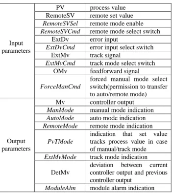
PID controller was implemented to have functions described above and applied to boiler control. Figure of implemented PID function block is shown in Fig. 4 [2]. PID function block in Fig. 4 has 10 inputs, 8 outputs, and 46 internal parameters. Explanation of inputs and outputs of PID function block is listed in Table 2. Inputs and outputs in italics in Table 2 depict that those are digital signals.
Fig. 4 Figure of implemented PID function block Table 2 Explanation of I/O in PID function block PV process value RemoteSV remote set value
RemoteSVSel remote mode enable
RemoteSVCmd remote mode select switch
ExtDv error input
ExtDvCmd error input select switch
ExtMv track signal
ExtMvCmd track mode select switch
OMv feedforward signal Input
parameters
ForceManCmd
forced manual mode select switch(permission to transfer to auto/remote mode) Mv controller output
ManMode manual mode indication
AutoMode auto mode indication
RemoteMode remote mode indication
PvTMode
indication that set value tracks process value in case of manual/track mode
ExtMvMode track mode indication
DetMv
deviation between current controller output and previous controller output
Output parameters
ModuleAlm module alarm indication
3.4 Application implemented controller to boiler control
The implemented PID controller was verified via power plant simulator using thermohydraulic model and has been applied to all boiler control loops in a middle-scale coal-fired thermal power plant. In this paper, application story is focused on feedwater control loop among boiler control loops. The flow of feedwater to the boiler drum is normally controlled in order to hold the level of the water in the steam drum as close as possible to the normal water level set point. Feedwater control plays a very important role in boiler control. The objective of feedwater control is to hold the drum level at normal level regardless of disturbance such as steam flow. The control logic applied to feedwater control is shown in Fig. 5. At start-up, feedwater is controlled by 1-element controller using drum level only. As steam flow increases above 25%, feedwater is controlled by 3-element controller using drum level, feedwater flow, steam flow. In 3-element control, feedwater controller is cascaded controller, that is, the output of master controller whose process signal is drum level and whose feedforward signal is steam flow is the set point of slave controller whose process value is feedwater flow.
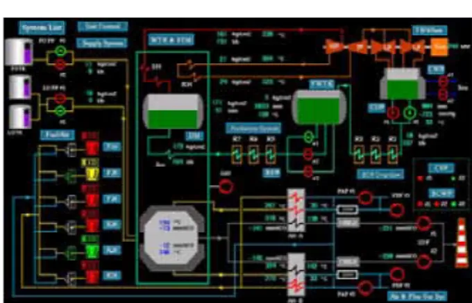
Fig. 5 Control logic diagram for feedwater control Parameters of PID controllers in Fig. 5 during commissioning is listed in Table 3. MMI for feedwater control and feedwater control result are shown in Fig. 6 and Fig. 7. respectively. Fig. 7 shows that drum level is hold as close as normal level while steam flow increases.
Table 3 Parameters of feedwater controllers Existing parameters Initial tuning parameters Fine tuning parameters Kp Ki P Ti P Ti PID-1 2 0.2 50 300 50 300 PID-3A 1.2 0.2 83.33 300 83.33 400 PID-3B 1 1.8 100 33.33 100 50
Fig. 7 Feedwater control result
4. RETROFITTING RESULT
In this section, retrofitting advantages and comparison of boiler characteristic test data after retrofitting with data before retrofitting are presented [2]. Images of main control room before and after retrofitting are shown in Fig. 8 and Fig. 9 respectively.
Fig. 8 Image of main control room before retrofitting
Fig. 9 Image of main control room after retrofitting
4.1 Retrofitting advantages
Through retrofitting, installed digital control systems have provided a lot of information that is helpful in operation and maintenance to operator and maintenance personnel. General advantages in retrofitting with digital control system are as follows :
- Improved reliability due to system redundancy
- Improved flexibility to modify the control logic
accompanied by equipment change
- Ease to change the control parameters via software - Easy and efficient monitoring the current data trend
and the historical data trend
- Easy modification of MMI display for operation - Ease to maintain the control system and to purchase
spare parts
4.2 Load change test results after/before retrofitting
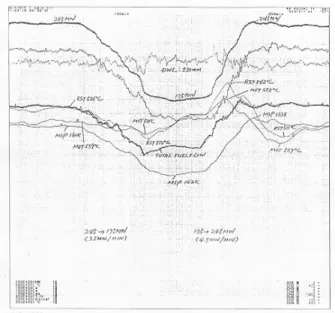
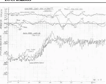
After retrofitting, load change test trend is shown in Fig. 10 while power at 245MW was decreased to 175MW at the rate of 3.5MW/min and then power was increased to 245MW at the rate of 4.5MW/min. Load change test trends before retrofitting are shown in Fig. 11 and Fig. 12. The rate of load change in Fig. 11 and Fig. 12 is 3MW/min.
Fig. 10 Load change (245→175→245MW) test data after retrofitting
Fig. 12 Load change (180→250MW) test data before retrofitting As shown in Fig. 10, 11, and 12, the response time after retrofitting is faster than that of test before retrofitting. Main steam pressure and main steam temperature can be considered as performance indexes. The deviations from the set point of main steam pressure and main steam temperature in load up and down test are listed in Table 4. Table 4 shows that the deviation from the set point of main steam pressure after retrofitting is much smaller than that of test before retrofitting although load rate is larger than that of test before retrofitting.
Table 4 Deviation data from set point during load change test Load change [MW] Load rate [MW /min] Main steam pressure [kg/cm2] Main steam temp. [oC] Reheated steam temp. [oC] Before retrofitting 250→ 180 3 +6, -4.8 +6.4, -5.6 +8, -30 After retrofitting 245→ 175 3.5 +1, -2.5 -1, -10 -14, -30 Before retrofitting 180→ 250 3 +6, -3.6 +4, -7.5 +14.4, -9 After retrofitting 175→ 245 4.5 +3, -0 +12, -13 +2, -13 Governor free test trend is shown in Fig. 13 during commissioning. Speed regulation was measured 4.2% at 210MW. No MFT happened during commissiong.
Fig. 13 Governor test trend during commissioning
5. CONCLUSION
In this paper, the some retrofitting experience is represented. Use of parameters of existing controllers is very helpful to commission after retrofitting although some cautions are required. Test results including load change test show that retrofitting has been successful. Recently, some analog boiler control systems in thermal power plants have been retrofitted with DCSs made in Korea owing to a successful retrofitting project described in this paper.
REFERENCES
[1] Günter Kelefenz, “Automatic Control of Steam Power Plants”, Hartmann & Braun AG., Minden, Biblio- graphisches Institut, Zürich, 1986
[2] Doo-Yong Park, et al., “Development of Integrated Distributed Control System for Thermal Power Plant”, KEPRI, Final Report of 96SJ39
[3] Seung-Hyun Byun, et al., “Improvement of a PID Function Block of a Domestic DCS”, Proceedings of the KIEE Summer Annual Conference, pp. 2108-2110, 2001