Reviews and Discussions on the Control Element Drive Mechanisms for the High
Temperature Gas-cooled Reactor
Dong-Ok Kim, Jong-Bum Kim, Yong-Wan Kim, Keun-Bae Park, Jonghwa Chang
Korea Atomic Energy Institute, 150 Dukjin-dong, Yuseong-gu, Daejeon, Korea, 305-353 1. Introduction
The High Temperature Gas-cooled Reactor (HTGR) becomes a cogent candidate for a heat source of the hydrogen production facility. The General Atomics in USA had developed a conceptual HTGR design of GT-MHR. Japan and China already had constructed HTGR systems, HTTR and HTR-10 respectively. Recently, Korea has made a plan of nuclear project, Nuclear Hydrogen Development and Demonstration (NHDD), and now the preliminary research work is on going.
Each benchmark HTGR system has its own control element drive mechanisms (CEDM). This paper presents reviews of the design characteristics of each CEDM and discusses the key technologies for NHDD system.
2. Control Element Drive Mechanisms 2.1 GT-MHR of GA
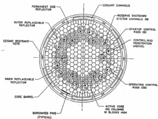
The reactor core of the Gas Turbine-Modular Helium Reactor (GT-MHR) is designed to provide 600MWt. It has 36 control rods in the outer reflector blocks and 12 in the core region. Each neutron control assembly has two control rods and two independent drives. And there are 18 reserve shutdown equipment units assembled into the neutron control assemblies[1]. Figure 1 shows
the core arrangement and the neutron control elements.
Figure 1. GT-MHR core arrangement
Figure 2 shows the neutron control assembly with reserve shutdown equipment. The control rod is lowered and raised with a flexible high nickel alloy cable. The cable load is monitored by load cells to detect a control rod or a broken control rod cable and to prevent excessive driving load. The motor is capable of minimum service life of 60 years.
The reserve shutdown equipment consists of a reserve shutdown hopper containing borated graphite
shutdown material and a fuse link mechanism which opens the hopper gate by means of an actuation rod.
Figure 2. Neutron control assembly with reserve shutdown equipment of the GT-MHR
2.2 HTTR of Japan
The High Temperature engineering Test Reactor (HTTR) is a HTGR system of 30MWt. The reactivity of the reactor is controlled by 16 pairs of control rods, which are individually moved by control rod drive mechanisms, and the reserve shutdown system[2,3], as
shown in Figure 3.
Figure 3. HTTR core arrangement
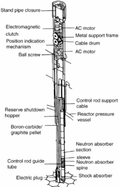
Figure 4 shows the control rod drive mechanism. The drive motor is coupled to the cable drum through the decelerator, the electromagnetic clutch and the gears. The maximum withdrawal velocity is limited by the decelerator. When the electric current is cut off by a scram signal, the clutch is separated to insert the control rod into the core by gravity. To protect the support cable from overloading, the velocity-limiting brake maintains the insertion speed constant during a reactor scram. The position indicator uses syncro-mesh transmitters. Various tests were performed to evaluate the reliability of the control rod system.
Transactions of the Korean Nuclear Society Autumn Meeting Busan, Korea, October 27-28, 2005
The reserve shutdown system consists of a hopper containing B4C/C pellets, a driving mechanism, a guide
tube, etc. In accidents when the control rod cannot be inserted, the electric plug is pulled out by the drive motor, and the neutron-absorbing pellets fall into the core by gravity.
Figure 4. Control rod system of the HTTR
2.2 HTR-10 of China
The 10MW High Temperature gas-cooled test Reactor (HTR-10) is a modular pebble bed type reactor[4,5]. Ten control rod systems and seven small
absorber ball systems are provided for the HTR-10 as shown in Figure 5.
Figure 5. Control rod arrangement in the HTR-10
Figure 6 shows the control rod drive mechanism. The magnetic damper connected to the stepping motor restricts the emergency insertion speed without any electric power to operate. The control rod position is transmitted by a synchro rotating 282˚ corresponding to the whole stroke. The dry film lubricant is adopted for the control rod drive mechanism. The performance tests for the control rod drive installation are carried out for the verification of its reliability, the feasibility study of the dry lubrication film, and demonstration of the emergency insertion time and speed of the control rod.
The small observer ball system consists of drive mechanism, ball storage vessel, ball supplier, gas blower and pressure vessel, pipeline, primary loop isolation valve, carrier gas valves and carrier gas bypass valves. The system has a function to remove the small absorber balls from the channels by pneumatic suction before the reactor re-operation.
Figure 6. Control rod drive mechanism of the HTR-10
3. Conclusion
The benchmark HTGR systems (GT-MHR, HTTR, HTR-10) adapted two independent control element drive mechanisms for reactivity control; the control rod drive system and the reserve shutdown system. And the performances of the control element drive mechanism were verified by various tests and experiments. Through the reviews of them, several important technical considerations of the CEDM can be found; the drive mechanism with high reliability, the lubrication in high temperature helium gas environment with strong radiations, the integrity of the steel components, and the reliable function for the reactor shutdown in any accident conditions. The same problems and requirements shall be considered in the NHDD system.
ACKNOWLEDGMENT
This study was supported by the Korea Ministry of Science and Technology through its National Nuclear Technology Program.
REFERENCES
[1] L.L. Parme, et al., Gas turbine-modular helium reactor conceptual design description report, General Atomics, Doc.No. 910720, 1996.
[2] T. Tatsuo, et al., Design of core components, Nuclear Engineering and Design, Vol.233, p. 71-79, 2004.
[3] Y. Tachesima, et al., Reactivity control system of the high temperature engineering test reactor, Nuclear Engineering and Design, Vol.233, p. 89-101, 2004.
[4] Z. Wu, et al. The design feature of the HTR-10, Nuclear Engineering and Design, Vol.218, p. 25-32, 2004.
[5] W. Yuanqiang, et al., Design and tests for the HTR-10 control rod system, Nuclear Engineering and Design, Vol.218, p. 147-154, 2004.