1. Introduction
It is a challenging task to make the paraplegic walk without the assist of the caregiver. RGO's (Reciprocating gait orthosis) have been introduced to assist the paraplegic to walk. An RGO is consisted of two KAFO's of which torso section on the top portion is a torso section including pelvic band. The patient wearing the RGO pushes the pelvic band backward with his/her trunk and one of leg braces moves forward. Thus he/she has to keep pushing the pelvic band in order to walk. Therefore during the gait with RGO, the energy expenditure is excessively great and the use of RGO is not widely accepted[1,2,3,4].
At KOREC, a prototype of a powered gait orthosis has been developed to reduce the energy consumption and the muscle fatigue. Each hip joint of the PGO is flexed by an air muscle operated by pressurized air enabling the patient to walk. The air muscle behaves like a human muscle and connects one side of the torso section to the upper part of the same side of the brace. The role of artificial muscle is to assist hip flexion during swing phase. Therefore, the patient can walk with less energy expenditure by using a PGO than using an RGO.The PGO a modification of an RGO incorporating two pneumatic muscle actuators(PMA), a compressed air system,pressure and joint angle sensors.
In the present study, PGO which controlled by fuzy algorithm for hip flexion and evaluated in two SCI patients.
In addition, hip flexion angles and foot pressure were measured and analyzed for SCI patients who used the developed PGO with the three-dimensional motion analysis system.
2. PGO CONTROL SYSTEM
2.1 Air muscle
The Air Muscle[5,6] is an extraordinary actuator that is small, light, and simple. It is soft, has no stiction, is easily controllable and exceptionally powerful. The Air Muscle consists of a rubber tube covered in braided plastic mesh shell which shortens in length like a human muscle when inflated with compressed air at low pressure.
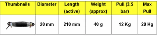
An Air Muscle has a power-to-weight ratio as high as 400:1, vastly outperforming both pneumatic cylinders and DC motors that can attain a ratio of only about 16:1. It has been in continuous development for advanced robotics work by Shadow since 1982, and is now available for use in a variety of applications as a powerful, lightweight actuator. Air Muscles are normally operated using compressed air in the 0-70psi (0-5 bar) range. Figure 1 is a specification of air muscle in this experiment.
Fig. 1 A specification of air muscle 2.2 PGO system
The concept of the PGO driving system is to couple the right and left sides of the orthosis by specially designed hip joints and pelvic section. The driving system of powered gait orthosis(PGO)
consists of the orthosis, sensor, control system. An supply system is composed of anair compressor, 2-way solenoid valve(MAC, USA), accumulator, pressure sensor. Role of
Development of Intelligent Powered Gait Orthosis for Paraplegic
SungJae Kang, Jei Cheong Ryu ,In Hyuk Moon, Kyung Hoon Kim, Mu Seung Mun
Korea Orthopedic & Rehabilitation Engineering
47-3 Kusan-Dong, Pupuoung-Gu, Incheon, Korea
(Tel : +82-32-500-0597; E-mail: kangsj@iris.korec.re.kr)
Abstract: In this study, we wolud be developed the fuzzy controlled PGO that controlled the flexion and the extension of each PGO's joint using the bio-signal and FSR sensor. The PGO driving system is to couple the right and left sides of the orthosis by specially designed hip joints and pelvic section. This driving system consists of the orthosis, sensor, control system. An air supply system of muscle is composed of an air compressor, 2-way solenoid valve(MAC, USA), accumulator, pressure sensor. Role of this system provide air muscle with the compressed air at hip joint constantly. According to output signal of EMG sensor and foot sensor, air muscles and assists the flexion of hip joint during PGO gait.
Fig 2.. PGO system
this system provide air muscle with the compressed air at hip joint constantly(Fig. 2).
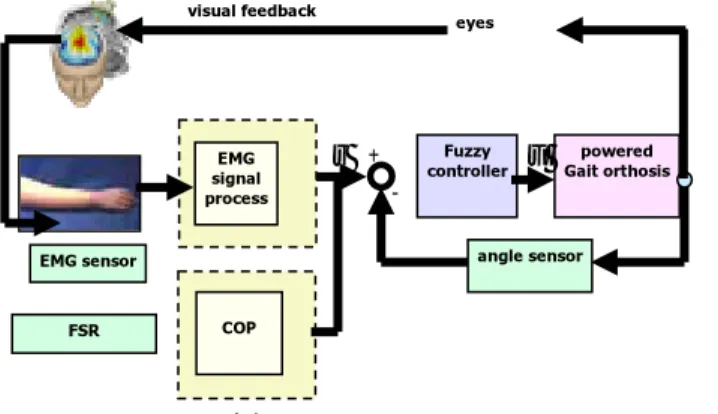
The schematic diagram of the proposed fuzzy controller is shown if Fig 3. It consist of 2 sensor and fuzzy controller.
Fig 3. The schematic diagram 2.3 FSR signal fuzzy set
Force Sensing Resistors(FSR) are a polymer film device, which exhibits a decrease in resistance with an increase in the force applied to the active surface. For COP measurement, we attached 4 foot sensor and calculated COP. Figure 4 showed that 4 FSR force can calculate COP.
The gait cycle is defined as the time interval between to successive occurrences of one of the repetitive events of walking. Stance phase is between initial contact to to toe off ..
Fig 4. COP measure
Fig 5. Gait Cycle
Figure 6. shown that a normal male subject COP movement. The trace shows initial contact at the back of the heel on the lateral side, with progressiono of the center of force along the middle of the foot to the metatarsal heads, where it moves medially, ending at the hallux. So horiziontal COP movement can be represent the fuzzy set .
x
y
Fig 6. COP movement
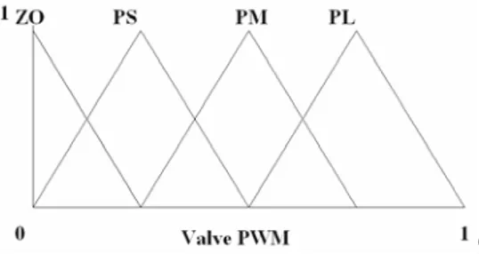
The basic idea of fuzzy[7] set theory introduced by Zadeh(1965) allow the degree of membership u to vary between 0 and 1 continuously. In order to inclulde the representation of COP in concept of fuzzy logic, the degree to which crisp values belong to a given fuzzy set is represented by a function known as a membership function. Typically, technical quantities are represented on the horizontal axis of the function and membership degrees on the vertical. Figure 7 show the membership function about COP movement. 2.3 EMG signal fuzzy set
EMG signal is the measured electric potentials produced by a voluntary contraction of muscle fibers. The frequency range of the EMG signal is within 0 to 2,000 [Hz] but the dominant energy is concentrated in the 30 to 500 [Hz] ranges, and the amplitude is limited to 0 to 10 [mV] (peak-to-peak) according to the muscle contraction [8]. Consequently, by measuring the amplitude of EMG signal, muscle activation can be detected because the amplitude of the EMG signal increases according to the increase of contraction force of muscle [9]. In this study, we apply smoothed MAV (SMAV) of the surface EMG to the
Total Weight :5.3kg(RGO 4kg + controller 1.3kg )
Air Pump Battery Solenoid valve Controller Air Muscle Li-polymer (14.8V/1500mAh) X Y 00 F Fx0 y F0 Fxy ) , (x1y1 F xy y x T F F F F F = 00 + 0 + 0 + ] ) ( ) ( 1 [ 2 0 00 0 1 T y xy x F F F F F X x= + + − + ] ) ( ) ( 1 [ 2 0 00 0 1 T x xy y F F F F F Y y= + + − + EMG signal process Fuzzy controller
r + u Gait orthosispowered y
- angle sensor EMG sensor eyes visual feedback COP FSR
Fig 7. membership function e detection of muscle activation.
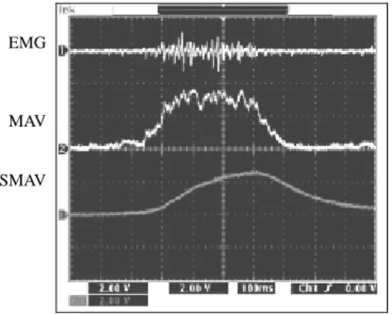
The SMAV is obtained by a signal processing from the surface EMG as shown in Fig. 8. To acquire the surface EMG from muscle, we use a commercialized active surface EMG electrode, DE-2.3, that contains a differential amplifier with 60 [dB] gain, and high pass filter (HPF) and low pass filter (LPF) with 20 [Hz] and 450 [Hz] cutoff frequency, respectively. Then, 60 [Hz] band rejection filter (BRF) filters off the power line noise from the output signal of the active electrode. We regard the signal x(t) as the EMG signal. From EMG signal x(t), the MAV signal u(t) called integrated absolute value (IAV) [10] is generated by an MAV circuit composed of a full rectifier and an integral circuit with 20 [dB] DC gain. The MAV signal is modeled as
dt
t
x
T
K
t
u
t T t∫
−=
(
)
)
(
(1)where K is the DC gain, and T is the integral range implemented by circuitries such as resistance R and capacitance C, respectively. Finally, SMAV signal y(t) which ripples were eliminated is obtained using the first order RC LPF. By comparing y(t) with the DT value, the muscle activation is recognized. From the transfer
Fig. 8. Examples of signals; EMG, MAV, and SMAV
Fig. 9. membership function of EMG signal de function of the RC LPF, the unit step function is obtained as
τ
t
e
t
y
(
)
=1
−
− (2)where denotes the time constant to be in inverse proportion to the cutoff frequency as follows:
c
f
π
τ
2
1
=
(3)Accordingly, the response characteristic of LPF shows that LFP with lower cutoff frequency has longer time delay. To realize a real-time myoelectric hand controller, the total processing time included the DT method should be not exceeding 300 [msec] [16]. In this study we design for the cutoff frequency of LPF to be used for smoothing MAV in order that the time delay is not exceeding 200 [msec]. It is known that the LPF with time constant reaches the steady state after the time. Hence, from (3) the cutoff frequency is obtained by the following constraint equation,
2
.
0
2
5
5
=
<
cf
π
τ
(4)From (4) fc is obtained as 3.979. In this study we set 4 [Hz] to the cutoff frequency of the LPF.
Figure 9 shows the membership function of EMG. 2.4 Fuzzy rule
Most fuzzy logic based systems use production rules to represent the relationships among the linguistic variables and to derive actions from sensor inputs. Production rules consist of a precondition (IF-part) and a consequence (THEN-part). In Table 1, 16 fuzzy rule shows if then fuzzy rule for controlling PGO. r1 : If e is ZO and de is ZO then CI is ZO r2 : If e is ZO and de is PS then CI is ZO r3 : If e is ZO and de is PM then CI is ZO … r14 : If e is PL and de is PS then CI is PM r15 : If e is PL and de is PL then CI is PL r16 : If e is PL and de is PS then CI is PL EMG MAV SMAV
Table 1. Rule base EMG/COP ZO PS PM PL ZO ZO ZO ZO ZO PS ZO PS PS PS PM ZO PS PM PL PL ZO PM PL PL 2.5 Defuzification
The result produced from the evaluation of fuzzy rules is, of course, fuzzy. Membership functions are used to retranslate the fuzzy output into a cris p value. The Center-of-Maximum Method (CoM) does this by computing a crisp output as a weighted average of the term membership maxima, weighted . by the inference results. Figure 10 illustrates CoM defuzzification for the air pump. The locations of the individual term membership maxima are indicated by the gray arrows and the inference result is pwm signal for air pump control.
Fig. 10.The membership function of fuzzy controller 3. Gait Analysis
Three subjects(39±2.8 years) who were two adult normal male and one paraplegic male participated in this study. Subjects were recruited from the laboratory staffs and patient of the hospital. Their heights and weights ranged from 170±1.7㎝, 60.5±7.5kg, respectively.
Subjects were performed the gait analysis five times per one month after gait training on PGO during about three months. In order to identify any kinematic value of subjects, we were used six infrared CCD cameras and spheric reflective markers of 25mm in diameter. Seventeen spheric reflective markers were mounted in rigid arrays secured to each body segments : theanterior superior Iiliac spine, sacrum, great trochanter, medial thigh, knee joint and ankle joint, medial tibia, foot. The analog position signals of each body-fixed markers were converted to digital form, fed on line to a computer, and stored
on a hard disc.
Fig. 11. Motion analysis system
Fig 12. Gait analysis
The raw data of the marker positions were passed through a filter, and analyzed with the built-in software in the three-dimensional motion analyzer system( Vicon 370; Oxford Metrics Inc., UK). To obtained kinetic data each lower limb joint of subjects, we measured ground reaction force using two force plate( 900×600㎜, 600×400㎜ in size; Kistler Co., Swiss).(Fig. 11)
Capacitance pressure sensor (Novel GmbH, Germany) were used to measure plantar pressure distributions during walking with PGO (Fig 12).
4. RESULTS AND DISCUSSION
The aim of this study ultimately is verifying that fuzzy PGO gait is more efficient than RGO for paraplegic, because the air muscle assists hip flexion power in heel off.
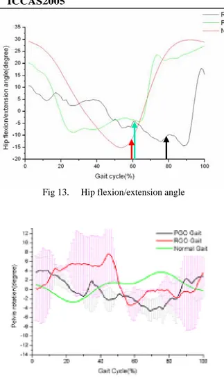
In figure 13, the gait characteristics of the paraplegic wearing PGO and RGO are compared with that of the normal person. At the heel contact in RGO and PGO gait, hip flexion angles are approximately 10 deg. while that of normal gait is approximately 30 deg. The smaller hip flexion angles of the
Fig 13. Hip flexion/extension angle
Fig 14. pelvic tilt angle
PGO and RGO gaits are due to the smaller step length. In normal gait, the duration of stance phase and swing phase are 60% and 40% of the total gait cycle respectively. In RGO gait, the duration of the swing phase is
reduced since the hip joint is flexed by the rotation of the pelvic band. The hip flexion angle fluctuates during the stance phase as the movement of the body center is unstable. On the other hand, in the PGO gait since the hip joint is flexed by the air muscle and not by the rotation of the trunk, the movement of the center of the body appears to be more stable than that in the RGO gait.
The ratio of the duration of the swing phase in PGO gait is 63±8% showing improvement from the RGO gait in which the duration of the swing phase is 79±4%. The gait speed is 61±3step/min for RGO gait and 77±2step/min in PGO gait respectively. During gait, the pelvic tilt is normally related to the balance of the body and the amount of energy consumption.
The pelvic tilt during the normal gait reduces the vertical movement of the hip joint and minimizes the vertical motion of the body center. In Figure 14, the pelvic tilts during the PGO and RGO gaits becomes larger than that of the normal gait. The reason is that since there are no knee flexion during
the PGO/RGO gait, larger pelvic tilt than that of the normal gait is needed for toe off. The fact that pelvic tilt during the PGO gait is relatively smaller than that of the RGO gait means that the movement of the body center is more stable in PGO gait because of the air muscle.
As shown in figure 15, at the initial heel contact during the normal person’s level walking, the pressure distribution is concentrated on the part of heel and, at the terminal stance phase, heavy concentration of the pressure is found at the metatasal part. As the mid stance the pressure distribution is almost even.
On the other hand, during the PGO gait, the pressure distribution conical shape concented on the heel and metatasal at the initial heel center and through midstance. In RGO gait, at the terminal stance phase the pressure hill move back to the mid foot as the patients tries to change weight bearing to the other limb.
The COP during the normal gait, starts from posteriolateral of the heel at the initial contact and travel almost linearly along the lateral to the midline during mid-stance phase. Then it moves to the medial part of the foot with distinct pressure concentration on the metatarsal break. However, in case of PGO gait, the COP starts from the heel and proceed to the metatasal. Then ate the pre-swings phase the C.O.P moves to the mid foot. The postions of the foot on which the value peak pressure are heel, metatarsal and toes, During the PGO gait, the peak pressure at the heel is more larger than normal gait.
(a) RGO gait (b) PGO gait Fig 15. COP movement
5. CONCLUSION
In this paper a PGO using PMA's for SCI patients is proposed. As the hip flexion angle and the pelvic angle is decreased during the gait with PGO, the patient can walk faster. A PGO controlled by fuzzy controller was developed and found to useful. The EMG signals seems to be a good tool to detect the intention of ambulation of the paraplegic and the unintentional motion of the PGO can be removed by using the EMG signals. Therefore, the proposed PGO can be a very useful assitive device for the paraplegics to walk.
6. Acknowledgment
This study was supported by a grant of the Korea Health 21 R&D Project, Ministry of Health & Welfare, Republic of Korea. (02-PJ3-PG6-EV03-0004)
6. References
M. KingR. C. Baker and B. Charlie, “Nonlinear unstable systems,” International Journal of Control, Vol. 23, No. 4, pp. 123-145, 1989.
Douglas R, Larson PF, DAmbrosia R, McCall RE. ,“The LSU reciprocation gait orthosis”, Orthopedics.,Vol.6,pp 834-839, 1983
Solomonow M, Best R, Aguilar E, et al. “Reciprocating gait orthosis powered with electrical muscle stimulation (RGO II): Part I. Performance evaluation of 70 paraplegic patients.”, Orthopedics., Vol 20, pp315-324, 1997.
Marsolais EB ,Polando G, Lehneis HR, Tashman S., ”Der gang von paraplegikern mit dem hybrid system aus FNS/orthesen Paraplegic walking with hybrid FNS/Orthotic system”, Orthopadie Technik, Vol. 49, pp 372-376, 1998. Klute, G. K. , J. M. Czerniecki, and B. Hannaford, “ McKibben Artificial Muscles : Pneumatic Actuators with Biomechanical Intelligence.” Proceeding of the IEEE/ASME 1999 International Conference on Advanced Intelligent Mechatronics (AIM’99), Atlanta, GA, Sep 19-22,1999
Chou, C.P. , B. Hanaford, “Measurement and Modeling of McKibben Pneumatic Artificial Muscles.”, IEEE Transactions on Robotics and Automation, Vol. 12, No. 1, pp.90-102, 1996. R. K. Mudi, N.R. Pal, “ A robust self-tuning scheme for PI- and PD type fuzzy controllers”, IEEE Trans. Fuzzy Syst., Vol. 7, No. 1, Feb., 1999
C. J. De Luca, “Surface Electromyography: Detection and Recording”, Delsys Incorporated, 2002.
C. J. De Luca, “The Use of Surface Electro- myography in Biomechanics,” Journal of Applied Biomechanics, Vol. 13, No. 2, pp. 135-163, 1997.
S. H. Park and S. P. Lee, “EMG Pattern Recognition Based on Artificial Intelligence Techniques,” IEEE Trans. Rehab. Eng., Vol. 6, No. 4, pp 400-405, 1998.