서 론 1.
광통신부품산업은 핵심 전략 산업으로 국가 차 원의 체계적인 광산업 육성정책이 요구된다.
광통신부품산업이 활용되는 범위는 정보통신산 업 바이오 유통 에너지 등으로 확산되어 광범, , , 위하게 활용되는 기간산업으로 발전 중이다 .
또한, FTTH의 본격화로 어느 기지(CO)에서 밀 집지역까지 하나의 광섬유를 포설하여 그 신호는
개의 으로
N OUN(Optical Network Unit) 분할되 고 이, N개의 ONU은 다시 N'개의 OUN'로 연
†장경천장경천 한국생산기술연구원장경천장경천, 한국생산기술연구원한국생산기술연구원한국생산기술연구원 E-mail : [email protected]
TEL : (062)600-6120 FAX : (062)600-6099
* 이동길 한국생산기술연구원,
** 장 훈 한국생산기술연구원,
속적으로 분배되는 네트워크 구조가 이루어질 것 이므로 이에 소요될 광통신 부품들의 수요가 크 게 증가될 전망이고, 약 2010년경에 요구되는 전송 용량은 현재의 배 이상으로 광통신
Data 100
용량이 기하급수적으로 증가하는 추세가 전망되 어 현재 보다 광통신 관련 제품의 수요급증이 예
상 된다 . 또한 광통신부품은 기술 개발 속도
가 가속화 되어 고속 성장이 예상되며 시장 경쟁 이 매우 치열해질 것으로 전망되고 기술적 선점 과 새로운 프로세스를 이용한 고부가 가치화가 절대적으로 요구되어지고 있다 특히 광통신 부품 중 Lid Glass의 Application은 Fiber array, fanout black, Silica optical waveguide
및 등의 광통신부품 제작에 필수적
chip splitter
광통신 부품 고온압축성형의 관한 연구 광통신 부품 고온압축성형의 관한 연구 광통신 부품 고온압축성형의 관한 연구 광통신 부품 Lid glass Lid glass Lid glass Lid glass 고온압축성형의 관한 연구
장경천†
․
이동길*․
장훈**A Study on the Optical communication part Lid glass A Study on the Optical communication part Lid glass A Study on the Optical communication part Lid glass A Study on the Optical communication part Lid glass
manufacture technology by high temperature and compression manufacture technology by high temperature and compression manufacture technology by high temperature and compression manufacture technology by high temperature and compression
molding molding molding molding
K.C. Jang, D.G. Lee, H. Jang
Key Words:
Key Words:
Key Words:
Key Words: Pattern core(
패턴코어), Cycle time(
생산 시간), Lid-glass(
리드 글래스)
Abstract
Data transmission capacity that is required in 2010 is forecasted that increase by optical communication capacity more than present centuple, and is doing increased demand of optical communication related industry product present. Specially, Lid glass' application that is one of optical communication parts is used in optical communication parts manufacture of Fiber array, Ferrule array, Fanout Black, Silica optical waveguide chip and splitter etc.
Also, it is used widely for communication network system, CATV, ATM-PON, FTTH and
system. But, Lid glass need much processing times and becomes cause in rising prices of
optical communication parts because production cost is expensive. The objectives, of this work
is to suggest the micro concave and convex pattern manufacturing technology on borosilicate
plate using high temperature and compression molding method. As a result, could developed
micro pattern Mold more than 5 pattern, and reduce Lid Glass manufacture cycle time.
송, ATM-PON, FTTH, DATA 통신 광장비 및, 시스템 등에 널리 활용되고 있으며, 낮은 삽입 손실과 PDL, 낮은 반사 손실 및 고정밀도 높은, 신뢰도 등이 요구되어지고 있다. 하지만 Lid 제작비용이 높아 광통신 부품에 모듈가격 Glass
상승의 원인이 되고 있고, 기존에 생산 방식인 가공방법 보다 대량 생산이 가능하고 원가 절감 을 할 수 있는 새로운 제조방법 개발이 절실히 요구되고 있다.
따라서 본 연구에서는 광통신 부품의 핵심 부품 인 Lid Glass에 원가를 절감하고 대량 생산을 하 기 위하여 Lid glass 제조에 금형을 이용한 고온 압축 성형법을 적용하고자 하였으며, 같은
를 가지는 의 성형 조건
Pattern depth Lid Glass
화하고 을 단축하고자 하였다
DB Cycle time .
고온 압축 성형 2.
금형 설계 2.1 Lid Glass
는 광섬유를 정렬하는 부분으로서 Lid Glass
Fiber array, Fanout black, Silica optical
및 등의 광 부품 제작에
waveguide chip splitter
필수적인 부품이다. Lid Glass application을 고온 압축성형법으로 금형을 이용하여 제조하기 위해 먼저 같은 패턴을 가지는 금형 제작이 필요하다.
에 에 패턴 설계도를 나타내었으
Fig.1 Lid glass
며, Fig.2에 5패턴 이상이 가공된 금형을 나타내 었다. Pattern은 4.14㎜폭의 5이상 패턴이 얻어지 도록 2.0㎜폭의 홈 패턴을 가공하였고 홈의 깊이, 는 50 ,㎛ 공차는 -2㎛이하로 패턴을 가공 하였다. 금형 제작에 사용된 소재는 높은 열 Lid glass
에 변형이 없고 열전도가 높은 카본 소재를 사용 하여 제작을 하였으며 금형 카본의 밀집도를 높, 이기 위하여 함침공정과 금형 표면을 코팅하여 제작하였다.
Fig.2 Lid-Glass mold Fig.2 Lid-Glass mold Fig.2 Lid-Glass mold Fig.2 Lid-Glass mold
고온압축 성형법 2.2
고온압축 성형법은 성형체(pyrex)를 질소 분위 기 및 진공 분위기에서 고온으로 가열하여 고압 으로 성형체(pyrex)를 성형하는 유리 제품 성형 방법이다.
성형체(pyrex)를 성형할 때 고온까지 가열 온, 도 보존과 추출 온도(200℃전후 까지의 냉각에 다) 소 많은 시간이 필요한 단점을 가지고 있지만, 적외선램프를 이용하여 금형을 균일하게 가열하 며 상하 금형의 개별 온도 제어를 할 수 있다, . 또한 압력과 위치 제어로 고정밀도의 프레스가 가능하고 프로세스 컨트롤로 성형 조건 온도 압( , 력 , 위치 시간 의 설정과 성형 상태를 리얼 타, ) 임으로 모니터에 표시할 수 있는 장점을 가지고 있다.
은 고온 압축 성형법 시스템의 개요도 나 Fig.3
타냈으며, Fig.4는 일반적인 고온압축법성형법에 사용되는 GMP207HV의 프로세스를 나타내었다.
는 가공된 금형 위에 성형체
GMP207HV (Pyrex)
를 정렬하고 밀폐 후
가스를 투입하여
가스 분위기를 만든다 다음 단계인. 1차 가압단계 까 지 적외선램프를 이용하여 성형 온도까지 가열을 하고, 1 , 2 , 3차 차 차 가압단계 별로 온도를 컨트 롤하며 성형 가압 후 추출 온도까지 냉각을 하, 고 성형품을 추출하는 System을 가지고 있다.((((Load)Load)Load)Load)
((((NNNN2 2 2 2 gas)gas)gas)gas)
Purging Oxygen Purging Oxygen Purging Oxygen Purging Oxygen
gas by N gas by N gas by N
gas by N2222gas gas gas gas Heating the molds Heating the molds Heating the molds Heating the molds and raw material by and raw material by and raw material by and raw material by infrared ray lamp infrared ray lamp infrared ray lamp infrared ray lamp
1
1 22 33 44 55 66 77 8 8 10 10 7 7 9 9 6 6 5 5 4 4 3 3 STEP.
STEP.
V No.
V No.
N2N2 PGPG AA BB CC TEMP.
(T) PRESS.
(P) POS.
(Z) V1 V1
Z1 Z1
V2V2 Z2Z2
V3 V3 P2
P2 P1
P1 PT1
PT1 P3P3
T5 T5 T4 T4 T2T2
T3T3 Tvu
Tvu TvTv
T1u T1u T1T1 ST1ST1 ST2ST2 Gv
Gv G1G1 G2G2 1
1 22 33 44 55 66 77 8 8 10 10 7 7 9 9 6 6 5 5 4 4 3 3 STEP.
STEP.
V No.
V No.
N2N2 PGPG AA BB CC TEMP.
(T) PRESS.
(P) POS.
(Z) V1 V1
Z1 Z1
V2V2 Z2Z2
V3 V3 P2
P2 P1
P1 PT1
PT1 P3P3
T5 T5 T4 T4 T2T2
T3T3 Tvu
Tvu TvTv
T1u T1u T1T1 ST1ST1 ST2ST2 Gv
Gv G1G1 G2G2 1
1 22 33 44 55 66 77 8 8 10 10 7 7 9 9 6 6 5 5 4 4 3 3 STEP.
STEP.
V No.
V No.
N2N2 PGPG AA BB CC TEMP.
(T) PRESS.
(P) POS.
(Z) V1 V1
Z1 Z1
V2V2 Z2Z2
V3 V3 P2
P2 P1
P1 PT1
PT1 P3P3
T5 T5 T4 T4 T2T2
T3T3 Tvu
Tvu TvTv
T1u T1u T1T1 ST1ST1 ST2ST2 Gv
Gv G1G1 G2G2
Fig.4 Process of GMP207HV Fig.4 Process of GMP207HV Fig.4 Process of GMP207HV Fig.4 Process of GMP207HV
성형 실험 방법 및 결과 3.
실험 방법 3.1
의 를 성형하기 위하여 홈 깊
Lid Glass Application
이 50㎛으로 패턴 가공된 금형에 성형체(Pyrex)를 정렬 시키고, GMP207HV를 이용하여 고온압축 성형 법으로 성형 실험을 실시하였다.
이 에 를 성형하기
Pattern depth 50㎛ Lid Glass
위하여 Molding Press , Mold Position 및 제어하면서 성형 실험을 하였고
Temperature , Table
은 조건 는
1 Molding Press , Table 2 Mold Position 조건, Table 3은 Temperature 조건을 나타내었다. 성형된 Lid glass의 Application에 홈 깊이를 차원3 레이져 측정기를 사용하여 측정된 홈의 깊이를 설계 값(50 ,㎛공차-2 )㎛ 과 비교하였다.
또한 성형 조건마다 성형에 소요되는 시간을 측정 하여 성형에 소요되는 Cycle time ,과 최적에 성형 조건을 DB화하였다.
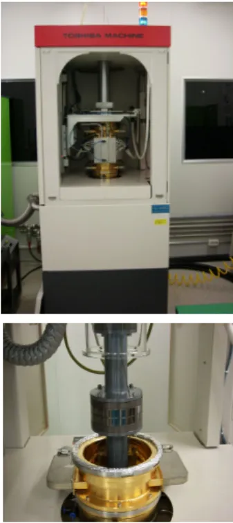
는 고온고압압축 성형기인 와 조
Fig. 5 GMP207HV
립된 Lid Glass 금형을 나타내었다.
Table 1. Condition of molding Press Table 1. Condition of molding PressTable 1. Condition of molding Press Table 1. Condition of molding Press Test Number P1
(kN)
P2 (kN)
P3 (kN)
1 8.0 6.0 0.2
2 20 18 0.4
3 20 18 0.4
4 20 18 0.4
5 20 18 0.4
6 20 18 0.4
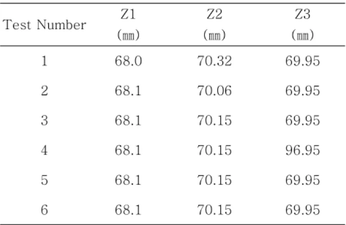
Table 2. Condition of Mold position Table 2. Condition of Mold position Table 2. Condition of Mold position Table 2. Condition of Mold position Test Number Z1
( )㎜
Z2 ( )㎜
Z3 ( )㎜
1 68.0 70.32 69.95
2 68.1 70.06 69.95
3 68.1 70.15 69.95
4 68.1 70.15 96.95
5 68.1 70.15 69.95
6 68.1 70.15 69.95
Table 3. Condition of temperature Table 3. Condition of temperatureTable 3. Condition of temperature Table 3. Condition of temperature Test
Number Tv ( )℃
Tvu ( )℃
T1 ( )℃
T1u ( )℃
T2 ( )℃
T3 ( )℃
T4 (℃)
T5 ( )℃
1 660 660 680 680 670 650 620 280 2 680 680 680 680 650 610 520 280 3 720 720 720 720 690 690 630 280 4 720 720 720 720 720 620 580 280 5 720 720 720 720 690 620 560 280 6 720 720 720 720 690 620 580 280
Fig.5 GMP207HV and Lid Glass Mold Fig.5 GMP207HV and Lid Glass Mold Fig.5 GMP207HV and Lid Glass Mold Fig.5 GMP207HV and Lid Glass Mold
성형 실험 고찰 3.2 Lid Glass
성형체 를 조건에 따라
Lid Glass (Pyrex)
를 이용하여 성형 실험을 하였고 성
GMP207HV ,
형된 Lid Glass를 3차원 레이저 측정기를 이용하 여 Pattern depth를 측정하여 설계값과 비교 하 였다.
는 를 측정하기 위한 차원
Fig.8 Pattern depth 3 레이져 측정기이고, Fig.9는 5 Pattern 이상 성형 된 Lid glass를 나타내었다.
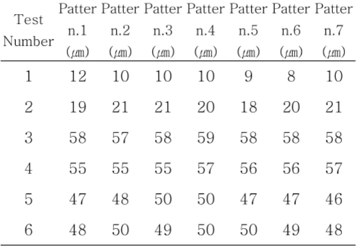
는 조건에 따라 성형된 의
Table 4. Lid Glass
측정결과 값을 나타내었고
Pattern depth , Table
는 성형 실험에 소요된 시간을 나타내었다
5. .
조건1 Test 결과 Pattern depth 측정값이 약10㎛
으로 성형이 이루어졌고, 13‘21“에 성형 시간이 소요되었다.
성형된 Pattern depth는 설계값(50 ,㎛공차-2 )㎛ 보다 40㎛낮게 성형되었다.
에 를 성형하기 위하여 조건
50㎛ Pattern depth 1
보다 Tv, Tvu에 온도를 각각20℃씩 높이고 Press 압력 P1, P2, P3를 각각 20kN, 18kN, 0.4kN으로
그러나 조건2 Test도 조건1 Test와 같이 설계값 공차 에 성형이 이루어지지 않음을 알 (50 ,㎛ -2 )㎛
수 있다.
이는 전체적인 성형 온도가 낮은 것으로 분석되 어 조건3 Test에서 조건2 Test와 같은 Press압력 을 가하고 전반적인 성형 온도를 높여 성형 Test 를 하였다.
조건3 Test에서 성형된 Pattern depth를 측정한 결과 전반적인 Pattern이 설계값(50 ,㎛공차-2 )㎛ 보다 깊게 성형되었다 이는. 3차 가압 시 온도 와 안정화 단계 온도가 높은 것으로 분석되어 T3
이를 각각 620 , 580℃ ℃으로 수정하고 조건4 Test 를 실시하였다.
조건4 Test의 Pattern depth를 측정한 결과 조건 와 같이 설계값 공차 보다 깊게 성 3 Test (50 ,㎛ -2 )㎛
형되었다.
설계값 보다 높게 성형이 이루어지는 것은 2차 성형 가압에 온도 T2와 안정화 단계 온도 T4가 높은 것으로 분석되어 온도를 각각 690 ,560℃ ℃ 로 설정하여 조건5 Test를 실시하였다.
조건5 Test에서는 성형된 시간이 15‘11“로 약20”
를 이전 Test 보다 Cycle time를 단축할 수 있었 지만, Lid glass의 Pattern depth를 측정한 결과
에서 설계값 Pattern 2, Pattern 3, Pattern 4 (50 ,㎛ 공차-2 )㎛ 을 만족하며 성형이 이루어졌고 그밖에,
은 설계값 보다 작게 성형되었다
Pattern .
조건5 Test에서 안정화 단계 온도 T4가 낮아 미 흡한 성형이 이루어진 것으로 분석되었고 조건, 6
에서 온도를 높인 로 설정하고
Test T4 20℃ 580℃ 성형 Test를 실시하였다.
조건6 Test 결과 각각 Pattern depth는48 , 50㎛ 로 설계값 , 49 , 50 , 50 , 49 , 48 (50 ,
㎛ ㎛ ㎛ ㎛ ㎛ ㎛ ㎛
공차-2 )㎛ 를 만족하며 성형이 이루어 졌고,
에 성형 이 소요되었다
15‘41“ Cycle time .
에 를 가지는 를 성
50㎛ pattern depth Lid glass 형 실험한 결과 Press 압력 P1, P2, P3는 각각
이 적합하며 성형 온도 차 20kN, 18kN, 0.4kN , 1
Table 4. Result of Pattern depth Table 4. Result of Pattern depthTable 4. Result of Pattern depth Table 4. Result of Pattern depth Test
Number Patter
n.1 ( )㎛
Patter n.2 ( )㎛
Patter n.3 (㎛)
Patter n.4 ( )㎛
Patter n.5 ( )㎛
Patter n.6 ( )㎛
Patter n.7 ( )㎛
1 12 10 10 10 9 8 10
2 19 21 21 20 18 20 21 3 58 57 58 59 58 58 58 4 55 55 55 57 56 56 57 5 47 48 50 50 47 47 46 6 48 50 49 50 50 49 48
Table 5.
Table 5.
Table 5.
Table 5. Cycle time result of Lid glassCycle time result of Lid glassCycle time result of Lid glassCycle time result of Lid glass Test Number Cycle Time
1 13'21"
2 15'32"
3 15'35"
4 15'35"
5 15'11"
6 15'41"
0 10 20 30 40 50 60 70
1 2 3 4 5 6 7
Pattern number
Pattern depth(um)
Design size Tolerance Test1 Test2 Test3 Test4 Test5 Test6
Fig.6 Fig.6 Fig.6
Fig.6 Pattern depth ofPattern depth ofPattern depth ofPattern depth of Lid GlassLid GlassLid GlassLid Glass
700 750 800 850 900 950 1000
1 2 3 4 5 6
Test number
Cycle Time (sec)
Cycle Time
Fig.7 Cycle time result of Lid glass Fig.7 Cycle time result of Lid glass Fig.7 Cycle time result of Lid glass Fig.7 Cycle time result of Lid glass
Fig.8 3D Three coordinate measuring M/C Fig.8 3D Three coordinate measuring M/CFig.8 3D Three coordinate measuring M/C Fig.8 3D Three coordinate measuring M/C
Fig.9 Lid-Glass manufacture Fig.9 Lid-Glass manufactureFig.9 Lid-Glass manufacture Fig.9 Lid-Glass manufacture
결 론 4.
를 성형하기 위하여 를
Lid Glass GMP207HV
이용하여 고온압축 성형 실험한 결과 다음과 같 은 결론을 얻을 수 있었다.
에 를 가지는 를
1) 50㎛ Pattern depth Lid Glass 성형하기 위하여 카본을 소재로 사용하여 금형을 가공 하였고, GMP207HV를 이용하여 고온 압축 성형 실험한 결과 5줄 이상에 Pattern을 가지는
를 성형할 수 있었다
Lid Glass .
최적에 성형 조건은 차 차 차 압력을
2) 1 , 2 , 3
각각 20kN, 18kN, 0.4kN과 각각 압력에서 온도 유지를 720 , 690 , 620℃ ℃ ℃일 때 Lid Glass설계 값(50 ,㎛공차-2 )㎛ 이내 Pattern depth가지는 Lid
를 성형할 수 있었다
Glass .
설계값 공차 이내 를
3) (50 ,㎛ -2 )㎛ Pattern depth 가지는 Lid glass에 성형 조건을 DB화하였고 성, 형 시 소요되는 Cycle Time은 15‘41“로 측정 되 었다.
후 기
이 연구는 2006년도 한국생산기술연구원의 첨 단부품사업으로 수행되었습니다.
참고문헌
(1) H. Jang, K. C. Jang and D. G. Lee, 2006,
"A Study on the moulding of a aspherical glass lens using Glass molding press,"
of the KSPE)
, Proceedings of the KSPE 2006 spring annual Meeting, pp. 191~192.(2) Park, Sooyong., 2002, "An Experimental
(3) Tea-Whan. Leem, Tea-Suk Jang.., 2005, "A Study on the Fabrication of Porous Sintered Materials for Glass Mold ,"
. of the KIVT
, Vol. 6, No. 6, pp. 468~472.(4) S.H Choi, H.K. Min 2007, "A Study on the Molding Technology for the Preform of Blow Molding Through Compression Molding "
. of the KSTP
, Vol. 16, No. 1, pp. 3~8.(5) Y.H Oh, H.C. Kim 1999, "A Study on the Compression Mold ablity for Continuous Fiber-Reinforced Polymeric Composites ―Part 1 : The Mechanical Propertis and the Cup-type Compression Moldability for Numbers of Needling"
. of the KSCM
, Vol.12, No. 5, pp. 31~39.