http://dx.doi.org/10.6111/JKCGCT.2013.23.6.296
Large-scale synthesis of the carbon coils using stainless steel substrate
Young-Chul Jeon and Sung-Hoon Kim
†Department of Engineering in Energy & Applied Chemistry, Silla University, Busan 617-736, Korea (Received September 2, 2013)
(Revised November 8, 2013) (Accepted November 15, 2013)
Abstract Carbon coils could be synthesized using C
2H
2/H
2as source gases and SF
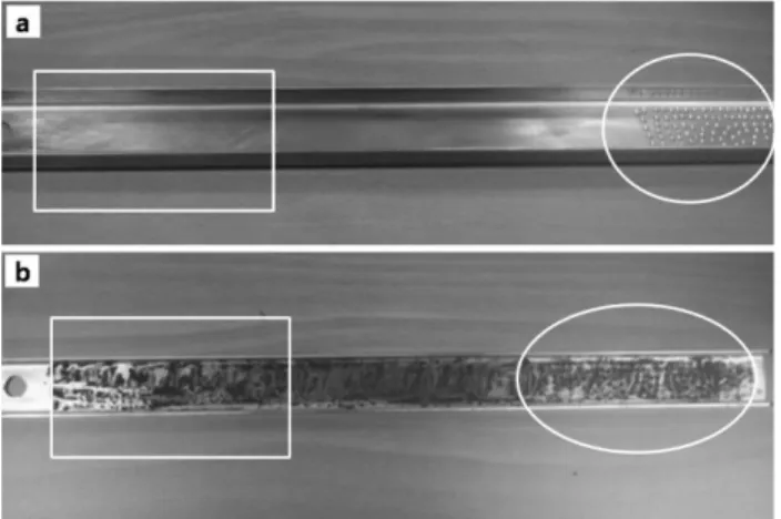
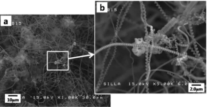
6as an incorporated additive gas under the thermal chemical vapor deposition system. A 304-type stainless steel was used as a substrate with nickel powders as the catalyst. The surface of the substrate was pretreated using a sand paper or a mechanical drill to enhance the production yield of the carbon coils. The characteristics of the deposited carbon nanomaterials on the substrates were investigated according to the surface state on the stainless steel substrate. The protrusion induced by the grooves on the substrate surface could enhance the formation of the carbon nanomaterials having the coils geometries. The cause for the enhancement of the carbon coils formation by the grooves was suggested and discussed with the surface energies for the interaction between as-growing carbon elements. Finally, we could obtain the massive production yield of the carbon coils by the surface pretreatment using SiC sand papers on the several tens grooved stainless steel substrate.
Key words Large-scale synthesis, Carbon coils, Stainless steel substrate, SF
6incorporation, Thermal chemical vapor deposition
1. Introduction
A particular interest in the synthesis of the carbon nanomaterials with a helical morphology, so called car- bon coils, has risen dramatically in recent year. Because of an unique spring-like geometry and a chirality, the carbon coils have been regarded as the high potential materials for the catalyst and the electromagnetic wave absorbers, nano/micro-sized tactile sensors, actuators, resonators, mechanical springs, and so on [1-4].
The carbon coils have been occasionally found as the low-content byproducts of the vapor preparation of the carbon fibers in the microwave plasma-enhanced chemi- cal vapor deposition or in the thermal chemical vapor deposition [5-8]. In addition, the carbon coils can be divided into the different categories based upon the heli- cal nature of the material: single helix, double helix, tri- ple helix, etc or the geometry size and shape: microcoil, nanocoil, wave-like nanocoil etc [9]. It was understood that the electrical properties of the one dimensional car- bon materials like the carbon nanotubes were varied according to their geometries and sizes [10]. Up to the present, the control over the synthesis of a specific type of the helical carbon material has been met with only
limited success. For the practical application of these materials, therefore, the controlled-characteristics for the coil morphology and geometry (diameter, pitch, length, and turning direction) with the large scale synthesis should be preferentially achieved.
Catalytic chemical vapor deposition (CCVD) has been found to be the reliable method that can produce the carbon coils [11]. However, due to the low yield of the carbon coils, normal CCVD process is not suitable for the scaled-up production of the carbon coils. To enhance the production yield of the carbon coils, various kinds of catalyst, substrate, and additives incorporation tech- niques have been widely investigated up to the present [12-23]. For the catalyst, Ni was known as an effective catalyst for the formation of the elastic carbon coils [12]. Co-silica or Fe-silica catalysts have been served as the substrates for the preparation of the carbon coils by catalytic pyrolysis of acetylene [13]. For the incorpo- rated additives, meanwhile, a trace of the sulfur-related species was regarded as the promising additives for the formation of the carbon coils. The carbon coils were reported to be well-synthesized by adding a trace of hydrogen sulfide (H
2S) [14], carbon disulfide (CS
2) [15], thiophene (C
4H
4S) as an impurity [16], or using WS
2as a catalytic material [17]. Previously, we also introduced the SF
6additive incorporation for the synthesis of the carbon nanofilaments [18-21]. SF
6was chosen to take the advantage for fluorine species characteristics regard-
†
Corresponding author
†
Tel: +82-51-999-5619
†
Fax: +82-51-999-5335
†