eISSN 2288-7407
스프레이 특성에 가솔린 - 바이오 디젤 혼합 연료의 효과
삭다 통사이1ㆍ임옥택2†
1
울산대학교 기계자동차공학과 대학원,
2울산대학교 기계자동차공학부
The effects of Gasoline-Biodiesel Blended Fuels on Spray Characteristics
SAKDA THONGCHAI
1, OCKTAECK LIM
2†1
Graduate of Mechanical and Automotive Engineering, University of Ulsan, Mugeo-dong, Nam-gu, Ulsan 680-749, Korea
2
Department of Mechanical and Automotive Engineering, University of Ulsan, 102 Daehak-ro, Nam-gu, Ulsan 680-749, Korea
Abstract >> The current study has investigated the effects of biodiesel blended with gasoline on the spray characteristics in a Constant Volume Combustion Chamber (CVCC). With the concentration of 5, 10, 15 and 20%
by volume, biodiesel was blended with commercial gasoline and performed on the macroscopic visualization test.
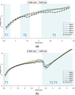
Pure gasoline and biodiesel were also tested as the reference. The shadowgraph technique was conducted in the constant volume chamber. The spray images were recorded by a high speed video camera with frame speed 10,000 frame per second. Fuel injection was set at 800, 1000 and 1,350 bar with the simulated speed 1,500 and 2,000 rpm. The back pressure was controlled at 20 bar. The spray angle and penetration tip were measured and analyzed by using the image processing. At the high injection pressure, the spray penetration length with the simulated speed 1,500 rpm showed that B100 was lower than GB00-20 whereas the spray penetration length with the simulated speed 2,000 rpm exhibited that GB blends and B100 were insignificantly different. Due to biodiesel concentration, its effects on spray angles were observed throughout injection periods (T1, T2 and T3). At the simulated speed 1,500 rpm, the spray angle of GB blends and B100 presented the same pattern following injection timing. In addition, when the simulated speed increased to 2,000 rpm the different spray angle of all blends disappeared at main injection (T3).
Key words : Gasoline-Biodiesel Blended(가솔린 - 바이오 디젤 혼합), Spray Characteristics(스프레이 특성), Shadowgraph( 그림자 그림)
†Corresponding author : [email protected]
Received : 2015.5.8 in revised form: 2015.6.24 Accepted : 2015.6.30 Copyright ⓒ 2015 KHNES
Nomenclature
: spray cone angle ATDC : after top dead center B100 : neat biodiesel BTDC : before top dead center
CAD : crank angle degree
CVCC : constant volume combustion chamber GB00 : neat gasoline
GB05 : gasoline 95% + biodiesel 5%
GB10 : gasoline 90% + biodiesel 10%
GB15 : gasoline 85% + biodiesel 15%
GB20 : gasoline 80% + biodiesel 20%
GCI : gasoline compression ignition
HCCI : homogeneous charge compression ignition
L : spray penetration length
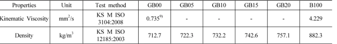
Table 1 Physical properties of GB
Properties Unit Test method GB00 GB05 GB10 GB15 GB20 B100
Kinematic Viscosity mm
2/s KS M ISO
3104:2008 0.735
9)- - - - 4.229
Density kg/m
3KS M ISO
12185:2003 712.7 722.3 732.2 742.6 757.1 882.3
PFV : photron fastcam viewer RPM : revolution per minute T1 : pilot injection T2 : pre injection T3 : main injection
1. Introduction
The high demand of petroleum based fuel conjunction with the decreasing its resource has stimulated many researchers to investigate the new source of energies such as alternative fuels. Biodiesel has been successfully applied in many countries. However, the application has been limited in only the compression ignition engines.
Therefore, it is interesting to use biodiesel in other types of engine, for instance, homogeneous charge compression ignition (HCCI) or gasoline compression ignition (GCI) engines
1).
The spray characteristics, the product of fuel injections, have the significant effects on combustion and emissions of engines. Therefore, the spray behaviors should be carefully investigated. Many researches have studied the spray characteristics of biodiesel fuel. Szybist and Boehman
2)found that biodiesel could advance the fuel injection timing and shorten injection duration when compared with diesel. For spray pattern, longer penetration tip with narrower spray angle was presented for biodiesel injection
3). However, Allocca and et al could not find the difference of spray pattern between biodiesel and diesel
4).
Gasoline direct injection via diesel common rail injection system has been investigated recently
5). They
found that spray penetration between diesel and gasoline showed not clear differences but mass flow rate of gasoline was lower than diesel due to its lower density.
For gasoline blended with biodiesel, there are a few researches to study the spray characteristics when injecting with diesel common rail injection system. To understand the GB spray behaviors, the CVCC and one-hole injector were employed to investigate the spray length and cone angle. The effects of injection pressure and engine speed have been clarified. The spray characteristics were analyzed by image processing from Matlab.
2. Methodology
The spray characteristics were conducted in CVCC via shadowgraph technique with variety of blended biodiesel concentrations
6). The injection pressure was controlled by means of a diesel common rail system. The spray images were recorded by a high speed camera.
Then, the image processing (Matlab) technique was employed to analyze the spray length and cone angle
7,8).
2.1 Test fuel
Conventional gasoline from a retail station and neat biodiesel from an industrial were utilized in this study.
The gasoline-biodiesel blends (GB) were mixed by
percentage of volume. The concentrations of biodiesel
were varied between 0 to 20% with 5% increment
(GB00-GB20), where G stands for gasoline and B stands
Fig. 1 The schematic diagram of the spray visualization system
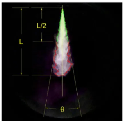
Fig. 2 The definition of the spray penetration length and the spray cone angle
Table 2 The simulated speed
1,500 rpm 2,500 rpm
Timing Duration (ms) Timing Duration (ms)
Pilot: 10CAD BTDC (T1) 300 Pilot: 31CAD BTDC (T1) 260
Pre: 3CAD BTDC (T2) 300 Pre: 3CAD BTDC (T2) 330
Main: 6CAD ATDC (T3) 700 Main: 7CAD ATDC (T3) 840
for biodiesel and the numeric value refers to the percentage by volume of biodiesel mixed with gasoline.
Some of the physical properties of GB following Korean standard were exhibited in Table 1.
2.2 Spray visualization system
Fig. 1 exhibits the schematic diagram of the spray visualization system. The volume of CVCC is appro- ximately 1,295 ml. It has six changeable ports such as quartz windows, injector and gas inlet and outlet port.
The common rail injection system consists of low pressure pump, common rail, one-hole injector, pressure controller, common rail solenoid injector peak & hold driver and multistage engine controller.
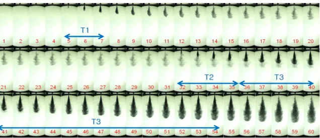
With knife edge technique, a high speed camera, Photron model SA3 was used to record the shadow spray pattern from light source through corrector lens. After recording at a speed of 10,000 frames/second, a thousand of spray images were transferred and saved in the personal computer via Photron FASTCAM Viewer (PFV) software.
2.3 Test condition