- 192 -
Wind Turbine Simulators for Control Performance Test of DFIG
Ahmed Abo-Khalil, Dong-Choon Lee Dept. of Electrical Eng., Yeungnam University Abstract - This paper proposes a new wind turbine simulator using
a squirrel cage induction for control performance test of DFIG (doubly-fed induction generator). The turbine static characteristics are modeled using the relation between the turbine torque versus the wind speed and the blade pitch angle. The turbine performance is subjected to a real wind speed pattern by modeling the wind speed as a sum of harmonics with a wide range of frequency. The turbine model includes the effect of the tower shadow and wind shear. A pitch angle controller is designed and used to protect the coupled generator by limiting the turbine speed to the maximum value. Experimental results are provided for a 3[kW] wind turbine simulator at laboratory.
1. Introduction
For laboratory-scale research of the wind energy conversion systems, it is important to develope a hardware simulator for the wind turbine which is able to produce realistic conditions that occur in a real wind turbine. Various simulators have pointed out different ways to achieve this aim and inherent problems of emulating a wind turbine or a generalized load. The advancement of turbines design, converter topologies and control algorithms increase the necessity of wind turbine simulators by using DC, induction motors or servomotors in laboratory. The main components of the wind turbine generation system consist of the high inertia turbine and a low inertia generator coupled with a shaft. Gearbox is usually used to change the slow rotation of the blades into a quicker rotation which is more suitable for generating electricity. The wind speed variations, gusts and turbulences affect the turbine output power. The wind speed pattern is distributed unequally over the wind turbine blades as the wind velocity is higher at higher altitude.
Several wind turbine simulators have been developed to simulate the wind turbine dynamics. There are different simulator designs depending on their applications. The simulator can be used in order to study different aspects related to the connection of the generator to the grid.
Since late 1990's, doubly-fed induction generators have become the most commonly used in wind power generation. It is a wound rotor type of induction machines with slip rings attached to the rotor and fed by the power converter. With DFIG, generation can be accomplished in variable speed ranging from sub-synchronous speed to super-synchronous speed. The power converter feeding the rotor winding is usually controlled in a current-regulated PWM type, thus the stator current can be adjusted in magnitude and phase angle. The rotor-side converter operates at the slip frequency and the power converter processes only the slip power. Thus if the DFIG is varied within 30% slip, the rating of the power converter is only about 30%
of the rated power of the wind turbine. In this type of machine control the net power out of the machine is a summation of the power coming from the stator and the rotor.
This paper proposes a complete wind turbine model for both steady state and transient condition for DFIG applications. The importance of aspects such as pitch angle control, the drive train, wind shear, tower shadow and wind speed simulator are investigated.
2. Operating Principles and Control of DFIG
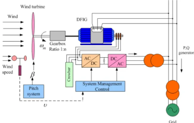
A schematic diagram of the overall system is shown in Fig. 1.
Back-to-back PWM converters are connected between the rotor and the utility grid. Above synchronous speed the four-quadrant converter operates as a source of active power delivering power to the grid parallel to the DFIG. Below synchronous speed, the four-quadrant converter provides active power from the grid into rotor circuit. Fig.
2 illustrates these relationships. The rotor voltage equation describes clearly the power flow in the DFIG for super-synchronous and
Fig. 1 Basic configuration of DFIG wind turbine system
1 1
0.75 0.75
0.5
0.25 0.5
0.25 0.0 0.0
-0.25 -0.25
P P
slip n/n
0.9 1.1
0.7 0.8 1.2 1.3
-0.3 -0.2 0.1 -0.1
0.3 0.2
s s
P/pr P/pr
s
r Pr
P PGC PGC
PG PG
(a) (b)
Fig. 2 Output power as a function of (a)slip (b)speed ratio
sub-synchronous operation as
(1) where is the voltage transformation ratio between stator and rotor and s is a slip.
Adjustment of the q-axis component of the rotor current can control either the generator torque or the stator active power of the DFIG.
(2) On the other hand, regulating the rotor d-axis current component can control directly the stator reactive power.
(3) It is noticeable that the stator active and reactive power components are proportional to the and , respectively. As the magnitude of is kept constant, both power components can be controlled by adjusting the relative rotor current components.
Using the turbine aerodynamic power characteristic and a suitable wind speed measurement, the stator power reference, input to the rotor-side control system, can be determined, as shown in Fig. 3.
The stator reactive power reference is determined by the desired system power factor.
Once both of the reference and measured active and reactive power are determined and controlled, simple proportional integral (PI) regulators can be used to control the d-q components of the rotor current as shown in Fig. 4.
2007년도 대한전기학회 하계학술대회 논문집 2007. 7. 18 - 20
- 193 -
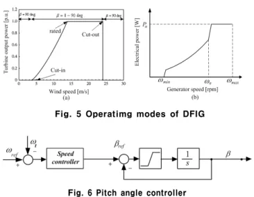
Fig. 6 Pitch angle controller Fig. 5 Operatimg modes of DFIG Wind
speed Vw
Low-pass filter
Ps*
Fig. 3 Calculation of stator power reference
ωr
e−jθ
-+ DFIG
DFIG DFIGDFIG
iarararar
ibr
PWM PWM PWMPWM converter
Grid
θ
SVPWM v v∗
∗b c
va∗
- + 1s
θe+- θr ωr
_ + Vdc
sl sl
e*
idr e
idr
iqre*
iqre v∗
vdre∗ +
- e qr
PI PI
Decoupling components
+ -Qmeas Reactive power
controller - + Pmeas Power controller
P* Q* Decoupling components
Fig. 4 Active and reactive power control
3. Wind Turbine Simulators
3.1 Wind speed simulator
An appropriate wind speed model is essential to obtain realistic simulations of the power fluctuations from wind turbine during continuous operation of the wind generation system. In general, the wind should be modeled as a stochastic process. However, the wind variation can be modeled as a sum of harmonics for the analysis of wind power generation system operation. The wind speed is simulated with the relation [1]
(4) where is the wind speed at time t, is the mean wind speed, is the harmonic frequency and is the harmonic amplitude. The harmonic amplitude at frequency can be expressed
∙ (5)
The traditional approach to modeling atmospheric turbulence as a stochastic process has been to use the Dryden spectra. For engineering purposes it is assumed that the power spectra of atmospheric turbulence can be approximated by the Dryden spectra.
The longitudinal Dryden power spectrum is defined by
(6)
where is the turbulence intensity, is the turbulence length and
is the harmonic frequency. The harmonic samples N are assumed equal to 15 and the frequency in the range 0.1-10 Hz.
3.2 Turbine characteristics and pitch angle control
The design of a wind turbine simulator begins by producing a wind speed pattern which is similar to the real wind in order to represent the interaction of turbine blades with the wind speed distribution over the rotor swept area. The resulting wind data are then applied to the static power curve , in order to determine
the driving torque with considering the pitch angle control. The wind turbine can be characterized by its curve, where the tip-speed ratio is defined as the ratio between the linear speed of the tip of the blade to the wind speed. It is shown that the power coefficient
varies with the tip-speed ratio. It is assumed that the variable wind turbine is operated at high values most of the time. The power captured by the wind turbine can be written as (4) [2]
(7) where is the air density, is the turbine radius, is the wind speed, and is the power coefficient, which for variable-speed pitch-controlled wind turbine depends on both the pitch angle and the tip speed ratio
(8) where is the blade rotational speed.
The pitch angle control of the blade is used to protect the turbines and to limit the output power at high wind speed. The output power is decreased as the pitch angle increases. The operating regions of the wind turbine are illustrated in Fig. 5. There are two wind turbine operating regions determined by wind speed. In the region less than the rated power, the blade pitch angle is set to give maximum power. The shape of the curve in this region reflects the basic law of power production, in which the power is proportional to the cube of the wind velocity. The second region occurs when sufficient wind is available for higher speed than the rated value. In this region the blade pitch control regulates the turbine speed to its maximum permissible value. The pitch angle controller consists of the speed controller and pitch mechanism of which block diagram is shown in Fig. 6.
3.3 Tower shadow and shear effect
The wind shear produces torque oscillations due to the wind velocity variation with the height, this torque can be modeled as [3]
(9) where tshear is an empirical coefficient of the wind shear.
The tower shadow torque oscillations can be modeled as
(10) where ≤ ≤
3.4 Control of squirrel-cage induction motor
Fig.7 shows the control block diagram of a squirrel-cage induction motor which implements the characteristics of wind turbines, where a conventional vector control method is used. The torque current is controlled continuously as mentioned in (7), (9), and (10). The motor torque reference is calculated using the turbine power equation and
- 194 -
Fig. 7 Control block diagram of induction motor.
(a)
(b)
(c)
(d)
(e)
0 [W]
1800[rpm]
0 [Deg.]
2 m/s/div
100 rpm/div
10[Nm]
2 Nm/div
750 W/div
15 Deg./div
0wind
0t
turbine
T
turbine
P
12[m/s]
0
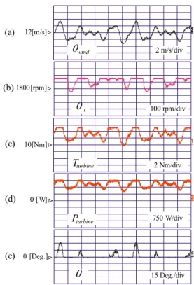
Fig. 8 Turbulent wind speed (a)Wind speed [m/s], (b)Turbine torque [Nm], (c)Turbine power [kW], (d)Pitch angle[deg.]
the turbine speed. The torque reference is then divided by the torque constant to obtain the torque current reference . The motor excitation current is supplied by controlling the d-axis current .
4. Experimental Results
The configuration of the 3[kW] DFIG wind turbine system at laboratory has been shown in Fig. 1. The characteristics of the wind turbine are simulated using a torque-controlled induction motor drive.
The motor is fed by a PWM controlled IGBT converter. The stator of the DFIG is connected to the utility grid. The rotor is connected to the grid through back-to-back PWM converters to provide a bidirectional power flow. The converter switching frequency is 5[kHz], and the current and the speed control sampling periods are 100[] and 1[ms], respectively.
Fig. 8 shows the DFIG performance for a turbulent wind speed.
The turbine power oscillations correspond to that of the wind speed.
The turbine torque and power follow the wind speed pattern with a
(a)
(b) 10[Nm]
10[Nm]
2 Nm/div turbine
T
2 Nm/div
Twind
(c) 10[Nm]
2 Nm/div
TGen.
0 [W]
(d)
PGen. 750 W/div
Fig. 9 Tower shadow and shear effects (a) Shear torque, (b)Shadow torque, (c)Turbine power, (d)Total turbine torque.
small delay due to system dynamics and inertia as shown in Fig. 8 (b) and (c). The pitch angle remains minimal at low wind speed.
However, the pitch angle increases when the wind speed increases higher than 13[m/s]. The tower shadow and wind shear are simulated and set to the standard value,
Figs. 9(a) and (b) show the turbine reference and measured torques. It is obvious that the turbine torque is influenced by the effect of tower shadow and shear torques. Also, the effect of these periodic pulsations are quite significant for the variations of the turbine torque and power as shown in Fig. 9(c) and (d).
5. Conclusions
To test the control performance of DFIG wind turbines, a new wind turbine simulator has been developed to emulate the real wind turbine operating conditions. The simulator uses a torque controlled cage-type induction motor as a wind turbine. The wind speed profiles have been expressed as a sum of harmonics with wide range of frequencies. The tower shadow and wind shear oscillations have been constructed using the existing functions. The tower shadow and wind shear have a quite significant effect on the total output torque. The pitch angle controller shows good performance in case of continuous wind speed variation. The newly designed wind turbine simulator can be used usefully to develop a control algorithm of the wind turbine generator.
This work has been supported by the KEMCO (Korea Energy Management Corporation) under project grant (2004-N-WD12-P-06-3-010-2006).
REFERENCES
[1] David Parker, "Computer based real-time simulator for renewable energy converters," IEEE International Workshop on Electronic Design, Test and Applications Proc., Jan. 2002, pp. 280-284 [2] Q. Wang and L. Chang, "An intelligent maximum power
extraction algorithm for inverter-based variable speed wind turbine systems," IEEE Trans. Power Electro., vol. 19, No. 5, pp.
1242 - 1249, Sept. 2004.
[3] M. Chinchilla, S. Arnaltes, and J. L. Rodriguez-Amenedo,
"Laboratory set-up for wind turbine emulation," IEEE ICIT Proc., vo. 1, 2004, pp. 553 - 557.