1. Introduction
Korea substantially depends on imported petroleum and natural gas in its energy industry. As Korea has been greatly growing industrially and economically, its
demand for fossil fuels including petroleum etc. has been rapidly increased. Therefore, it is very important and urgent to develop alternative energy sources which can provide a solution to the environmental pollution problem by inhibiting CO 2 production and further
Performance Prediction & Analysis of MGT Co-generation System
Kwang-beom Hur*, Jung-keuk Park, Sang-kyu Rhim, Jae-Hoon Kim
Performance Prediction & Analysis of MGT Co-generation System
Kwang-beom Hur*, Jung-keuk Park, Sang-kyu Rhim, Jae-Hoon Kim
As the distributed generation becomes more reliable and economically feasible, it is expected that a higher application of the distributed generation units would be interconnected to the existing grids. This new market penetration using the distributed generation technology is linked to a large number of factors like economics and performance, safety and reliability, market regulations, environmental issues, or grid connection standards.
KEPCO, a government company in Korea, has performed the project to identify and evaluate the performance of Micro Gas Turbine (MGT) technologies focused on 30, 60kW-class grid-connected optimization and combined Heat & Power performance. This paper describes the results for the mechanical, electrical, and environmental tests of MGT on actual grid-connection under Korean regulations. As one of the achievements, the simulation model of Exhaust-gas Absorption Chiller was developed, so that it will be able to analyze or propose new distributed generation system using MGT. In addition, KEPCO carried out the field testing of the MGT Cogeneration system at the R&D Center Building, KEPCO. The field test was conducted in order to respond to a wide variety of needs for heat recovery and utilization. The suggested method and experience for the evaluation of the distributed generation will be used for the introduction of other distributed generation technologies into the grid in the future.
Micro Gas Turbine(MGT), Grid-connection Operation, Combined Heat & Power(CHP), Exhaust-gas Absorption Chiller(EAC) Key words
Abstract
* Korea Electric Power Corporation (KEPCO), Korea
■E-mail : [email protected] ■Tel : (042)865-5323 ■Fax : (042)865-5489
increasing the energy efficiency.
As a part of efforts to cope with current energy and environmental problems, a micro distributed cogeneration system has been lately considered as it can be utilized in industrial factories, hotels, hospitals, office buildings and others. Such cogeneration system has high total energy efficiency over 70% by producing both electric power and heat.
Meanwhile, many countries something like U.S.A.
have a keen interest in the micro gas turbine cogeneration system, which is completely different from the conventional cogeneration system having adopted the gas engine system and the gas turbine system and further has higher competitive power in the aspect of initial investment as well as better efficiency. It is under development by several global companies. Particularly, Capstone Turbine Corp., an American company, has already launched its products on the market. Japan has developed the micro gas turbine cogeneration system on the basis of the main system of the Capstone's product that it introduced. R&D Center, Korea Electric Power Corporation is exerting its utmost efforts to meet the Korea's need to accelerate the spread of the micro cogeneration system in parallel with such efforts of advanced countries. This paper is to mention mainly the basic performance test of the micro gas turbine cogeneration system installed at R&D Center, Korea Electric Power Corporation and the contents relating to the exhaust gas absorption hot and chiller utilizing the exhaust gas produced by the micro gas turbine.
2. Status of Development and Utilization of the Small Gas Co- generation System in Korea
It can be thought that the small gas co-generation system is very suitable for Korea which is poor in energy resources for the following advantageous reasons:
1) It has a high total energy efficiency of 70~90% by producing electric power and heat energy at the same time and utilizing both the cooling capability and the heating capability effectively through utilization of the exhaust gas.
2) It enables the end user to reduce the electric charge by reducing the contracted power capacity and further to sell electric power back to the power company to gain some money.
3) Since private companies can participate in the cogeneration industry as a part of policies for supply of electric power, it can reduce the power company's own demand for new power.
4) Since it uses the city gas, a clean fuel, it can decrease environmental pollution by inhibiting emission of nitrogen oxides and carbon monoxide.
Apart 17,700
Hotel 1,106 Office Building
5,210 Entertainment
2,300
Industrial 18,000
Houspital 6,100
Total Capacity : 111,030㎾
Complex Building 60,600
Table 1 Status of Installed Small Gas Co-generation Systems by Uses of Buildings (2004)
3. MGT Performance Characteristics
3.1. Selection of research model
The gas turbine has been already widely used for power generation and aircraft jet engines, but the one with a small capacity below 1,000kW was little used because its competitive power was poor in the aspects of heat efficiency and product cost. However, its heat efficiency has been greatly improved and its price has been much lowered through recent technological innovation. Currently, advanced companies, such as Bowman, Capstone, Elliot, Honeywell, Turbec, etc., have succeeded in commercialization thereof, and its market is being formed in earnest. Particularly, Capstone, which was established in 1988, has commercialized the micro gas turbine generator for the first time in the world, and sold more than 3,000 units of a 30kW class and a 60kW class so far. They are now in operation for more than 3,000,000 hours in total.
Capstone is a specialty manufacturer specialized in the MGT which is scheduled to launch the 200kW class micro gas turbine in the future.
3.2. MGT performance specification
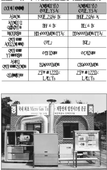
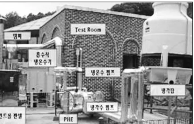
Major specifications of Model 30KW, 60KW -class MGT are shown in the following Table 2, and Fig.1 shows a photograph of 60KW-MGT co-generation system in the KEPCO.
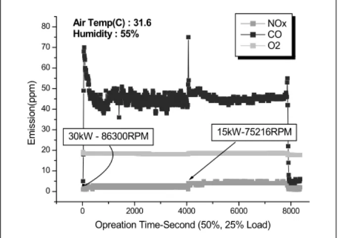
Fig.2, 3 show the start characterisitics of 60KW-MGT operation condition, especially 1) environmental- friendly power generation system which has just below 5 - 6 ppm-Nox ppm 2) have a very short time to full load within 4 minutes
Characteristic Performance Performance (60kW MGT) (30kW MGT)
Power 60kW NET(±2) 28kW NET(±1)
Thermal
Efficiency 28%(±2) 25%(±2)
Fuel Flow 849,000kJ/hr (HHV) 440,000kJ/hr (HHV) Exhaust
Temperature 305 ℃ 275 ℃
Exhaust
Mass Flow 0.49kg/s 0.31kg/s
Total
Exhaust Energy 571,000kJ/hr 327,000kJ/hr Emissions NOx (<9ppm) NOx (<9ppm)
@15%O2 @15%O2
Fig. 1 60kW class Micro Gas Turbine(MGT) Co-generation system (Korea Electric Power Corporation) - Capstone Turbine Corp. C60 mode
Fig. 2 60kW MGT Operation Curve
Table. 2 30Kw & 60kW class MGT performance specifications
4. Simulation of Performance Analysis of the Exhaust gas
Absorption Chiller for 30KW MGT
In order to enhance the economical efficiency of the micro gas turbine system, the total efficiency of the
system should be enhanced by recovering the exhaust gas from the turbine at the best. In case heat is recovered in the form of hot water, such recovery is available through an exhaust gas recuperator, but a place where the system is to be installed is restricted by the condition that hot water should be continuously used throughout a year. However, in case the heat source available from the exhaust gas is used for air- conditioning, such as cooling and heating, its availability gets to be greater as the using time zone and the scope of the place where the system is to be installed get to be greater.
The exhaust gas temperature of the Capstone's micro gas turbine is in the range of 300 ~ 260℃ which is lower than the exhaust gas temperature of the general turbine due to the heat exchange of the turbine outlet exhaust gas with air for combustion as made for enhancing the generation efficiency at the recuperator.
In the case that in this temperature range, the exhaust gas is used as the heat source for driving the exhaust gas absorption hot and chilled water generator, the absorption cooling cycle gets to adopt a single effect cycle or a double effect cycle. However, in the case of the single effect cycle, the recovered quantity of heat gets to be great but the cooling COP gets to be disadvantageously lowered. On the other hand, in the case of the double effect cycle, the cooling COP is high but the recovered quantity of heat is disadvantageously small.
There is a study
(1)suggesting a method for recovering the exhaust gas, the exhaust heat in the form of hot water and heating the dilute solution through the recuperator installed in the middle section between the low temperature recuperator of the double effect series flow cycle and the high temperature recuperator, but in this case, because the cooling capacity should be greater than the actually recovered quantity of heat, in the micro gas turbine often used for a base load, the cooling capacity gets to be greater than the base load and it is difficult to recover the hot water heat when the heating function is operated, which is a disadvantage.
In this research, operation and design conditions were examined by analyzing the single + double effect cycle
(2)for enabling the said problem to be solved,
Fig. 3 60kW MGT Partial Load Operation
Table. 3 Performance of the exhaust absorption hot and chilled water generator
Characteristic Unit Performance
Cooling capacity kW(USRT) 46(13) Heating capacity. kW(kcal/h) 48.1(41,400) Cold water inlet/outlet temp. ℃ 12 / 7.6
Hot water inlet/outlet temp. ℃ 50.4 / 55
Hot/Cold water rate ℓ/min 150
Hot/Cold water
Pressure drop in machine kPa(mAq) 27.5(2.8) Cooling water inlet/outlet temp. ℃ 32 / 38
Cooling water rate ℓ/min 250
Cooling water
Pressure drop in machine kPa(mAq) 37.3(3.8)
thermodynamically in the normal condition.
For calculation, the generation capacity of the Micro Gas Turbine was determined by adopting the Capstone's 30kW model (C30). The performance is already described , as Table 3.
5.1. Analysis of cycle for EAC System
For analysis of the cycle in the normal condition, any heat loss and any pressure loss were ignored in the system, and calculation was made by combining the heat conservation expression and the mass conservation expression for components at each point on the cycle under the thermodynamic equilibrium condition. And, as for physical property expressions for the Li-Br aqueous solution, the McNeely
(4)physical property expression was used.
1) Mass Conservation Expression
(1) (2)
2) Energy Conservation Expression
(3)
3) Outlet Temperature Difference
As for the inlet and outlet temperature of the recuperator, the effectiveness of the recuperator and the energy conservation expression were used under the counter flow condition, and for analysis of heat exchange of components including the absorber, the leaving temperature difference (LTD) method
(3)was adopted.
LTD A =T(1)-T(32) (Absorber) (4) LTD C =T(25)-T(34) (Condenser) (5)
LTD E =T(36)-(21) (Evaporator) (6) LTD G1,DE =T EXH2 -T(5) (High Temp. Regenerator) (7) LTD G1,SE =T EXH3 -T(45) (Auxiliary Regenerator) (8) 4) Quantity of Recovered Heat from Exhaust Gas
For calculation of enthalpy of mixed gas to be required for calculation of the quantity of the exhaust gas recovered from the micro gas turbine, composition of the exhaust gas was obtained from the following combustion equation under the complete combustion condition as follows:
(9)
Assuming that volumetric ratios of components of natural gas are CH 4 =89.7%, C 2 H 6 =6.7%, C 3 H 8 =2.6%
and C 4 H 10 =1.0%, composition equivalent to natural gas has a value of C 1.149 H 4.298 , and assuming that the mixed exhaust gas is the ideal gas, each component value and the enthalpy value of the mixed exhaust gas are as shown in Expression
(10), and for each coefficient value, data of Kee, R. J.
(5)were used.
(10) (11) Parameter values to be required for analysis of the
Parameter Value
LTDA, LTDE(℃) 3.0
LTDC(℃) 4.0
Texh1(℃) 261
εEX,H 0.75
εEX,L, εEX,A 0.8
T(31), T(32) (℃) 30, 35
T(35), T(36) (℃) 7, 12.5
Table. 4 Calculation parameters
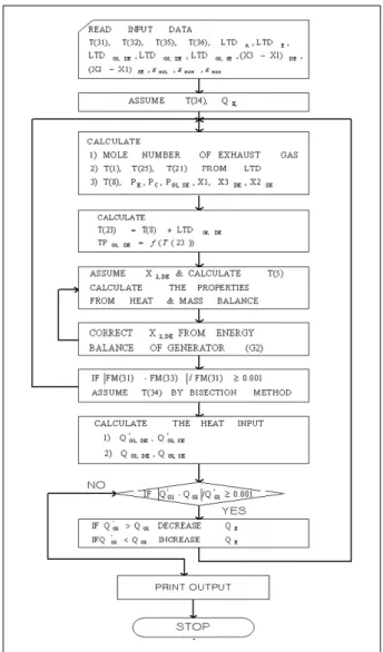
cycle are shown in Table 4, and the flow chart of the calculation program is shown in Fig. 5
5.2. Result of Calculation
Fig. 6 shows the change in the cooling capacity of the system and the quantity of heat recovered, depending upon the change in ∇ X DE , the concentration difference of the double effect cycle under the condition of
∇X SE =2%,∇LTD G1,DE =30℃, LTD G1,SE = 30℃ and T exh1 =261℃. It shows that as the value of ∇X DE is increased, the efficiency of the double effect cycle is improved to increase the total cooling capacity, and thus, the maximum cooling capacity is available in the range of 4%, and that in the range over 4%, as the quantity of heat recovered of the high temperature regenerator is decreased, the total cooling capacity gets to be lowered. It was shown that as the value of ∇X DE was increased, the quantity of heat recovered of the double effect cycle was decreased, but no change occurred in the total quantity of heat recovered as the exhaust heat was recovered in the single effect cycle.
Fig. 7 shows the effect depending upon the change in the outlet temperature difference (LTD G1,DE ) of the high temperature regenerator of the double effect cycle under the condition of ∇ X SE =3%, ∇ X DE =4%,
Fig. 4 Schematic diagram of Single +double effect Li-Br water absorption cycle
Fig. 5 Flow chart of analysis for EAC design
Fig. 6 Effect of concentration difference of double effect cycle on cooling capacity and total heat recovered
LTD G1,SE =30℃ and T exh1 =261℃. It was shown that as the outlet temperature difference is increased, the change in the total quantity of heat recovered is small, but the system cooling capacity was greatly increased due to the increase in the heat recovered of the double effect cycle having a great effect on the increase in the system cooling efficiency.
5.3. Result of simulation
1) An appropriate concentration difference of the single + double cycle was found to be of about 3% in the single effect cycle and of about 4% in the double effect cycle, respectively.
2) As the outlet temperature difference of the regenerator of the single + double cycle was smaller, the total cooling capacity of the system was proportionally increased. Therefore, in order to maximize the cooling capacity by recovering the exhaust heat from the micro gas turbine, it is necessary to consider improvement of the heat exchange efficiency of the regenerator within the allowable pressure loss of the exhaust gas from the micro gas turbine.
6. Test setup for MGT Co-generation system
Fig. 8 is a schematic diagram of the experimental micro gas turbine cogeneration system. It comprises the 60kW class MGT as described above, the exhaust gas absorption hot and chilled water generator, and the recuperator, and the exhaust duct connection work and the cooling water pipeline work were conducted so that each experiment might be conducted by respective systems, and further a separate control box was installed so that the operation may be controlled and the numeric value may be ascertained. A demonstrational operation and performance experiment on the micro gas turbine, a performance experiment on the micro gas turbine absorption hot and chilled water generator, a performance experiment on MGT and a performance experiment on the micro gas turbine recuperator are scheduled to be conducted by using this experimental system. This paper will be complemented by adding such experimental results by Feb. 2006, the deadline for final submission of the paper.
Fig. 7 Effect of LTDG1of double effect cycle on cooling capacity and total heat recovered
Fig. 8 Schematic diagram of MGT cogeneration system
7. Conclusion
The exhaust gas from the MGT is continuously emitted at approximately 300℃ and even when it is emitted into the atmosphere, it causes no environmental problem because it is clean. Therefore, how efficiently and variously the exhaust heat can be utilized will be a key to the micro gas turbine cogeneration system. In this research, a simulation for the exhaust absorption hot and chilled water generator utilizing the exhaust gas from the micro gas turbine was conducted, and as a result, some 13 USRT class was found to be appropriate for 30KW-MGT and 26 USRT class was found to be appropriate for 60KW-MGT. On the basis of this result, these kinds of exhaust gas absorption hot and chilled water generator was manufactured and an experiment was conducted on it in linkage with the micro gas turbine.. It is expected that such experimental result will be the foundation for making up and spreading various cogeneration systems in Korea which is currently at the initial stage for spreading the small co- generation system.
References
[1] H.Kojima, M.Edera, M,Nakamura, M.Oka, A. Akisawa and T.Kashiwagi, 1997, “Advancement of double effect absorption cycle by input of low temperature waste heat,”Trans. of the JSRAE, Vol.14, No.3, pp 221-232.
[2] H.Asano, T.Fujii, X.Wang, T.Origane, M. Katayama and U.Inoue, 2002, “An Exergy Analysis of LiBr-Water Absorption Refrigerators,”Trans. of the JSRAE, Vol.89, No.4, pp 301-312.
[3] M.D. Oh, S.C. Kim, Y.L. Kim and Y.I .Kim, 1993,
“Cycle analysis of air-cooled, double- effect absorption heat pump with parallel flow type,”International Absorption Heat Pump Conference, ASME, AES-Vol.
31, pp. 117-123.
[4] McNeely, L., 1979, “Thermodynamic Properties of Aqueous Solutions of Lithium Bromide”, ASHRAE Transactions, Vol. 85, Pt. 1, pp. 413-434.
[5] Kee, R. J., Rupley, F.M., and Miller, J.A., 1991, “The Chemkin Thermodynamic Data Base,”Sandia Report, SAND87-8215B.