논문 2012-49-9-25
무선센서네트워크를 위한
에너지 인지형 네트워크 구성 및 라우팅 기법
( An Energy Aware Network Construction and Routing Method for Wireless Sensor Network )
에이에스엠 산와르 호센*, 이 혁 로**, 조 기 환****
( A. S. M. Sanwar Hosen, Hyeak-ro Lee, and Gi-hawn Cho )
요 약
센서들이 동적으로 운용되는 무선네트워크 환경에서는 비용을 줄이고 신뢰성 있는 네트워크를 구축하는 것이 무엇보다 중 요하다. 본 논문에서는 네트워크 수명을 연장하기 위해 노드들이 수행하는 작업을 다수의 노드에게 분담하는 계층구조 기반의 에너지 인지형 네트워크 구성과 라우팅 기법을 제안한다. 이는 궁극적으로 노드들이 공평하게 에너지를 소모하기 위함이다. 노 드들의 계층 구조에서 싱크노드는 일단의 게이트웨이 노드를 선정한다. 선정된 게이트웨이 노드는 각각의 클러스터 안에서 클 러스터 헤드를 선정함으로써 논리적 클러스터를 구성한다. 클러스터 헤드는 감지 센서들로부터 데이터를 수집하고, 수집된 데 이터는 게이트웨이 노드를 통해 싱크노드로 전달된다. 실험결과 제안한 네트워크 구조는 에너지 소모의 원천을 감소시키고, 효율적으로 데이터를 전달하는 기반이 되고 있음을 확인하였다.
Abstract
In Wireless Sensor Networks (WSNs) where deployed sensors are not stationary, the most important demand of is to design a cost effective and reliable network. This paper proposes an energy aware network construction and routing scheme, which is based on the hierarchical approach to distribute the task in some sensors in order to prolong the network lifetime. It aims to make even the energy consumption on constitute nodes. With the node hierarchy, the sink initiates the construction by electing gateway nodes in the network and the elected gateway nodes participate to form logical clusters by electing a cluster head in each cluster. Then, the cluster heads aggregate data from the sensing sensors and transmit the data to the sink through the gateway. Our simulation result illustrates that the proposed scheme provides a basement to reduce the source of energy dissipation in network construction, and as well as in data routing.
Keywords : wireless sensor networks, routing, mobility, energy efficiency
Ⅰ. Introduction
Growing wireless communication infrastructure has
* 학생회원, *** 정회원-교신저자, 전북대학교 컴퓨터 공학부
(Div. of Computer Science and Engineering, Chonbuk National University)
** 정회원, 한국과학기술정보연구원 (KISTI)
접수일자: 2012년4월5일, 수정완료일: 2012년9월7일
been enabled to develop low-cost, low power, multifunctional sensor nodes. Wireless Sensor Network (WSN) is generally defined as a collection of large number of collaborating, tiny sensor nodes that collect data through monitoring a sensor field of interest and disseminate them to sink node.
Here, the notable issue comes from dynamic topology along with node mobility in order to design a well-consolidate network for gathering information.
The node mobility feature poses several challenges in a network such as packet loss, link failure, network construction, network maintenance, and network partition. These may significantly degrade the expected throughput of the network as a whole.
Especially, node and link failures bring about a serious effect on the network partition. With the node mobility, a sensor node would be out of the communication range from the other nodes. High computational and maintenance burden may lead to quick death of the constituted sensor nodes. In addition, the death of an intermediate node results in one of reasons for a link failure. This network partition requires a network reconstruction frequently, so dissipates more energy of sensor nodes, and results in make short of network lifetime.
Therefore, an efficient network design can be fruitful in every aspect of the WSNs applications. To resolve the frequent death of a sensor node, tasks should be distributed among the sensors evenly. The most common approach to construct a WSN is to make use of logical and/or physical clusters. In order to effectively maintain mobile sensors in a cluster, even to collect data from a missing node, the network construction method has a critical role.
This paper proposes an Energy aware network Construction and Routing method (ECR) for WSN.
The proposed WSN is constructed based on the hierarchical approach to distribute the task in some sensors. It aims to reduce even the energy consumption on constitute nodes to keep the network lifetime longer as it is possible. The main rationale consists of twofold; the cluster formation in logically and the hierarchy of the duty nodes in nature. The sink initiates the construction by electing Gateway Node(GN)s in the network and the elected GNs participate to form clusters by electing a Cluster Head(CH) in each cluster. While the GN acts as a coordinator to manage the node mobility, the CH plays the role as an aggregator of data from the sensing sensors. The aggregated data are transmitted
to the sink through the GNs directly or in multi-hops fashion.
The rest of the paper is organized as follows. We briefly discuss the related works in section Ⅱ. We explain ECR as details in section Ⅲ. Our simulation results are presented in section Ⅳ. Section V presents our conclusions.
Ⅱ. Related Works
Several network models for WSN, such as DLER[1], PEGASIS[2], TEEN[3], are proposed in terms of the static scenario of sensor nodes. In practice, however, the node mobility feature is strongly required in many application areas such as location tracking. In the dynamic topology, cluster based network modeling and hierarchical routing protocol are widely adopted as discussed below.
LEACH[4] is a cluster-based routing protocol, that utilizes a randomize rotation of CHs to evenly distribute energy load among sensor nodes in a network. Initially, a certain number of CHs are selected and the corresponding clusters are formed with the CH. A CH will periodically send data requests to its member sensors to send data through the CHs to sink. Sensor node which does not receive the request from its CHs realizes that it has moved out from its cluster and sends the join message to nearby CHs in order to join into the new cluster.
However, in-flight packets are not correctly routed the time disconnected from the old CH and the time connected with the new CH.
RHVC[5] is a landmark-based hierarchical routing protocol. The sink is considered as a first landmark.
Each sensor broadcasts its control packet at R hop distance. When a sensor receives this control packet, it checks the sender's ID. If its ID is bigger than neighboring nodes, then it becomes a second landmark. Each elected sensor sends it to the sink.
Getting this information, the sink makes a HVC(Hexagonal Virtual Coordinate) chart of
landmarks and transmit it to at most X distance for all deployed sensors in the network. Each node maintains the HVC chart to get the auxiliary routing path to transmit data to the sink using the greedy forwarding method. With this method, the problem is that it leads to the large number of control packets and consumes more energy to construct a virtual coordinate system and to maintain the chart.
RGR[6] is based on geographic and optimistic forwarding routing. The assumption behind this protocol, a node is aware about the location of itself as well as the neighbor's location, where location information can be exchanged using one-hop beacon or piggyback in the data packet's header. When a source wants to transmit a packet, it gets the location of the destination first and then attaches it to the packet header together with its own location.
This protocol is not efficient in the energy dissipation because data or control packet overhead will be increased due to the location tracking information for the neighboring nodes in each transmission.
EER[7] assumed that two CHs are required to support the mobility of nodes inside a cluster. Over the CHs, a GN is responsible to forward data to the sink and performed an additional task to find out the missing node from the CH. This approach leads to increase the number of death nodes in near future.
The frequent death of some intermediate nodes may come from link failure and network partitions. As a result, more reconstruction of the network will be required, so more energy is consumed to make short the network lifetime. Moreover, it will be increasing the packet latency in the sense of occupied time slots by the sensors to the sink, which may another cause of power dissipation.
It is observed that most of the previous works construct WSN without considering the computational cost, control packet overhead, and packet loss. But all the issues come in parallel with energy consumption.
Our work emphasizes on the expected network lifetime by reducing the computational overhead as
well as by recovering the missing data, because sensed data lost is a vital fact to achieve the goal of the WSN applications.
Ⅲ. The Propose Energy Aware Network Construction and Routing
This section represents a hierarchical approach from network construction to data forwarding phase.
Our work is based on the assumptions as follow. The ID of each node is unique, nodes are homogeneous, energy constrained, mobile and able to adjust their transmission range. The constituted nodes has a transmission range R. They make use of the basic TDMA technique in it's MAC layer. After completion of the construction phase, all the deployed sensors will maintain their allocated TDMA schedule.
The proposed scheme consists of three phases. The first phase is called initial network construction phase, in which the sink starts to elect GNs to forward data from a CH to the sink. The elected GNs will participate in the CH election process to forward data from nodes to GNs. After completing the CH election process, CHs elect the normal sensors as member sensors to forward data to respective CH nodes. The second phase is called data forwarding phase, where member sensors forward their sensed data to corresponding CH nodes. If required, the CH will aggregate the data from member sensors and forward it to the GN. Finally, the GN nodes will forward it to the sink. The last phase is called network maintenance phase, where network reconstruction and TDMA reassignment will be performed with reflecting of the node mobility and low energy level of CH and GN nodes.
1. Network Construction Phase
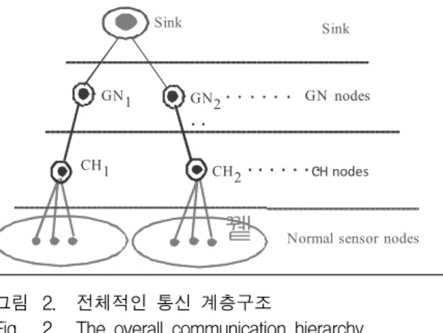
This phase establishes a task hierarchy from the sink to normal sensor nodes as shown in Fig. 2. To set-up a stable network, this phase constructs the network in different stages, these are as follows.
1.1 Election of GNs
The sink first initiates to elect GNs in the network. Here, GN has a transmission range 2R. It broadcasts a <hello> message by setting a timer ts
to the deployed sensor nodes. If sensor nodes received the <hello> message, they send back the
<ack> message to the sink with <node_id,
node_loch, node_energy, node_velocity> within the
time ts, where node_id is the unique ID of a node,node_loch is the current location, node_energy is the
residual energy of a node, node_velocity is the mobility of a node. When the timer expires, the sink will sort out the received list and compute the highest energy level of nodes and the distance between GNs, if the distance is dist(i,j) = 2R in between two adjacent nodes i and j, then it will select GNi and GNj as the GNs. After electing the GNs, the sink will notify the nodes by an <ack>message with the information of elected GNs. To elect the GNs and CHs node, highest energy level and lowest mobility of nodes are more preferable.
1.2 Election of CHs
Each of elected GN participating to elect a CH.
The GN again broadcasts the <hello> message with a timer tg to receive the <ack> messages. Sensor nodes received the message within the transmission range R send back an <ack> message with the information of <node_id, node_loch, node_energy,
node_velocity>.
If a GN received the <ack>messages within the time tg, it will elect a CH node within the region. When the timer expires, GN will broadcast the <ack> message to the elected CH with the information of member sensor nodes. On receiving the <ack> message, CH creates a TDMA based on the provided information by the GN, and broadcasts the <ack> to the member sensor nodes.
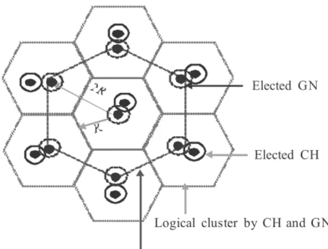
1.3 Logical Cluster Formation
Now, the entire network is divided into logical clusters. The lower clusters are grouped with normal
Logical cluster by sink
Logical cluster by CH and GN Elected CH Elected GN
그림 1. 잘 구성된 클러스터의 예
Fig. 1. An example of well-formed clusters.
sensor nodes and a CH node. The upper clusters are grouped by a CH node and a GN, where logical clusters are connected in hierarchically. Fig. 1 shows an example of well-formed clusters, which stand with the different nodes(e.g., sink, GNs, and CHs).
The overall network construction sequence can be summarized as;
a. Logical cluster formed by the sink: This cluster is initiated by the sink to cover the entire network by elected GNs.
b. Logical cluster formed by the GN: The elected GN initiates by electing a CH within its region, so it forms a logical cluster with the elected CH.
c. Logical cluster formed by the CH: The member sensor nodes are grouped by their respective CH, so they are individually formed a cluster.
2. Data Forwarding Phase
The proposed network construction is based on the hierarchical approach, where communication links are logically connected among the sensor nodes from sensing environment to the sink. The normal sensor nodes are connected with their respective CH, and CHs are connected with their corresponding GN, then the constituted GNs are connected to the sink.
At the data routing point of view, the normal sensor nodes forward their sensed data through their
뀉
GN1 GN2
. . .
. .
CH1 CH2
. . .
GN nodes
CH nodes
Normal sensor nodes Sink Sink
그림 2. 전체적인 통신 계층구조
Fig. 2. The overall communication hierarchy.
respective CH. The CH is considered as an aggregator of sensed data from their member sensors and forwards it through the GN. Finally, the GN is responsible to forward data to the sink directly or multi-hops fashion based on the current location of the sink. Fig. 2 shows an example of the overall communication hierarchy to forward data from the normal sensors to the sink.
3. Network Maintenance Phase
Our scheme is based on the cluster formation in logically and the hierarchy of the special duty nodes.
Along with the movement of the constituted nodes, the logical shape of clusters would be getting to be varied into a not-working one. In addition, moving of the dutied nodes may be sometimes destructible of the hierarchical structure of the network. These factors eventually bring about some degree of inefficiency in our scheme. Therefore, two kinds of network maintenance are required, that is, local maintenance and network reconstruction.
3.1 Local Network Maintenance
Firstly, the network requires the maintenance, when the sensor nodes are out of communication range may the reasons of velocity or frequent death of node for lack of battery supply. That is, if the CH node doesn't receive any data from a node within the predefined time tm, it will inform to the corresponding GN for the fact of that the node seems to be
missing. The GN node will broadcast a <hello>
message to the transmission range 2R, in order to mainly ask the node about the current location. The message is the same as the election of CH, but it includes to request to send the remaining data within the time tm.
On receiving the <hello> message, the node sends back an <ack> with the remaining data and current location to the initiating GN within the time. After receiving the <ack> message, the GN will compute the distance with the current CH node. If the distance is within the CH’s communication range between the CH node and the missing node, the GN will inform to the CH to reassign the time slot for the missing node, else it will inform the missing node to stop the transmission to the CH and the CH to eliminate the node from its member list. Otherwise the node will be considered as a death node.
3.2 Network Reconstruction
This will be required in the different situations.
When the sink doesn't receive any data from a particular GN may be the reasons of the death of the node or out of communication range due to the GN’s mobility, then sink will be initiated to elect a new GN in that cluster. And if a GN doesn't receive any data from the corresponding CH node may be the same reasons, then GN will be initiated to elect a new CH in that cluster. If the number of election of GN or CH node is over the predefined threshold, the sink will be initiated network reconstruction entirely, because this situation means that the current special dutied nodes’(CHs or GN's) residual energy level will be below to work in stable.
Ⅳ. Performance Evaluation
We used the network simulator, ns2[8], which is a discrete event based simulator. The primary performance measurement is the increased network lifetime due to energy awareness on the network
construction and data routing. Also, we are interested in how the comparative measure scales with network size. Sensor network may generally involve thousands of nodes, thus scaling to large size network is essential for an efficient routing protocol to be applicable to sensor networks.
1. Network Model
To represent the sensor node’s mobility, we make use of the random waypoint model, which is similar to CBR[9]. Each mobile node moves at the direction of 0 to 360o to change the current location for a distance
d with a velocity between [velocity_min, velocity_
max], where d is exponentially distributed. Sensors
may be reflected into the valid network area when they hit the network boundary.In order to calculate the transmitting and receiving energy, we used the first order radio model which is mainly borrowed from[9], as shown in Fig. 3.
In this model, transmitter and receiver dissipate
E
elec= 50 nJ/bit to run a transmit and receive. To
amplify the signal, amplifier dissipates Eamp = 100 pJ/bit and the idle listening dissipates 330mJ. So the transmission cost of the transferring k-bit message to a distance d is given by the following equations (1) and (2).
×
× ×
(1)
Transmit
Electronics Tx Amplifier
Receive Electronics K bit packet
((( ))) ((( )))
d K bit packet
ETx (k,d)
Eelec *k Eamp *k*d2
ERx
Eelec *k
그림 3. 일차 무선 전파 모델 Fig. 3. First order radio model.
× (2)
The experimental results are represented ECR compare with EER[7] respect to the different criteria.
We assumed that the sink is located at the center of the deployed sensor field with the same velocity of sensor nodes. Sensor nodes are randomly deployed in a (410*410) meter square of (L*W) area and the transmission range R is 100m. The sensor nodes move in a random way point with the velocity (2-6) m/s. The data size is 64 bytes for both data and control information. We assumed the probability of packet drop ratio is 0.0 to 0.2.
2. Performance Results
2.1 Optimized Number of GNs and CHs in a Large Scale Network
For comparison the number of GNs and CHs election, the simulation area is varied from (110*110) to (810*810), and 6400 nodes are gradually deployed in the area.
The result in Fig. 4 shows that ECR reduces the number of GN and CH nodes up to 7.53%. This mainly comes from that our scheme makes use of one GN and one CH node in a cluster rather than the two CHs and a GN node in EER. It means that more number of CH nodes in each cluster consume more energy for broadcast the control packets. It is
0 50 100 150 200
110 210 410 610 810
The num ber of G Ns and
CH s
Network size (m*m)
ECR EER
그림 4. 선출된 GN과 CH의 수
Fig. 4. The number of elected GNs and CHs.
observed that in EER, 5% nodes more lead to quick death than the ECR.
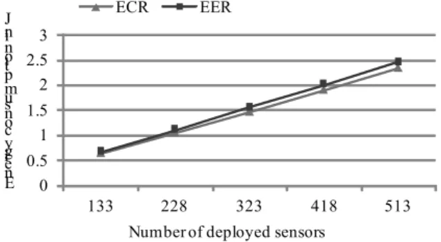
2.2 Energy Efficiency in Initial Construction To calculate the energy consumption as a whole, 133 to 513 nodes are randomly deployed in the simulation area, so 410*410, in different rounds. As it is, the energy consumption depends on the number of elected GNs and CHs nodes, ECR consumes 0.025%
less energy in it's election phase due to the less number of elected CHs than that of the EER. Based on the required energy consumption, the network construction cost is shown in Fig. 5.
0 0.5 1 1.5 2 2.5 3
133 228 323 418 513
Ene rgy cons um ptio n in J
Number of deployed sensors
ECR EER
그림 5. 초기 네트워크 구축 비용 Fig. 5. Initial network construction cost.
2.3 Idle listening Energy Dissipation
We applied 2ms for each time slot in the TDMA in it's MAC layer and considered 19 frames as a round. It is estimated that in EER, the normal sensor nodes dissipate 3.62% more energy than the ECR due
0 2 4 6 8 10 12 14 16
10 20 30 40 50
Een ergy dis sipa tion in J
Number of rounds
ECR EER
그림 6. 휴식상태에서의 에너지 소모량 Fig. 6. The energy dissipation in idle listening.
to the reason of two consecutive time slots allocated by two CH nodes for a normal sensor node in a cluster, as shown in Fig. 6.
2.4 Overall Energy Consumption
There are 133 nodes randomly chosen among the deployed sensors to transmit data to the sink in their respective allocated time slot. To calculate the routing cost, we considered 19 clusters formed in the simulation area.
In each round, average 5 member sensor nodes are connected with their respective CHs and participated in data forwarding in their allocated time slots. The Fig. 7 shows the result of overall energy consumption which is calculated the total energy of network construction cost, routing cost, and idle listening dissipate energy.
0 5 10 15 20 25
10 20 30 40 50
Ene rgy cons um ptio n in J
Number of rounds
ECR EER
그림 7. 전체 에너지 소모량 Fig. 7. Overall energy consumption.
2.5 Packet Delivery Ratio
To analyze the throughput level, we increase the
0 0.1 0.2 0.3 0.4 0.5 0.6 0.7 0.8 0.9 1
20 40 60 80 100
Pac ket d eliv ery ratio
Number of noramal sensors
ECR EER
그림 8. 네트워크 크기에 따른 패킷 전송률
Fig. 8. Packet delivery ratio according to the network size.
number of deployed sensors to participate in the data forwarding from the sensing environment to the sink.
Fig. 8 shows the observed successful packet received ratio at the sink of both ECR and EER. Our scheme outperforms the EER because the less number of CH nodes are connected with the GNs as intermediate nodes to forward data to the sink.
Ⅳ. Conclusion
This paper deals with a network construction and routing scheme The main idea is to make use of the hierarchical structure from the initial network construction to data forwarding. The GN concept in each cluster is advantageous to observe the moveable sensors and collect data from the missing node. In our work, we observed that, tasks distributed in different node in a hierarchical fashion can reduce the overall computational cost. That is, it can reduce the link failure and network partition. Therefore, our scheme will lengthen the life time of the network effectively. For the future work, we would like to enhance this scheme for a location free self-organize routing method where sink and nodes are mobile.
References
[1] C. Liang and J. Lin, “Distributed Landmark Election and Routing Protocol for Grid-Based Wireless Sensor Networks,” in proc. on Inter’l Symp. on Parallel and Distributed Processing with Application (ISPA), pp. 187-191, 2010.
[2] S. Lindsey and C. Raghavendra, “PEGASIS:
Power-Efficient Gathering in Sensor Information Systems,” in proc. on Conf. on Aerospace, vol. 3, pp. 1125-1130, 2002.
[3] M. Manjeshwar and D. Agarwal, “TEEN: A Routing Protocol for Enhanced Efficiency in Wireless Sensor Networks,” in proc. on the 15th Inter’l Symp. on Parallel and Distributed Processing, pp. 2009-2015, 2001.
[4] W. Heinzelman, A. Chndrakasan, and H.
Balakrishnan, “Energy-Efficient Communication Protocol for Wireless Microsensor Networks,” in
proc. on the 33rd Inter’l Conf. on System Sciences, pp. 3005-3014, 2000.
[5] J. Sheu, M. Ding, and K. Hsieh, “Routing with Hexagonal Virtual Coordinates in Wireless Sensor Networks,” in proc. on Conf. on Wireless Communications and Networking, pp. 2929-2934, 2007.
[6] S. Yang, C. Yeo, and B. Lee, “Robust Geographic Routing with Virtual Destination Based Void Handling for MANETs,” in proc. on VTC, pp. 1-5, 2010.
[7] H. Sarma, A. Kar, and R. Mall, “Energy Efficient Routing Protocol for Wireless Sensor Networks with Node and Sink Mobility,” in proc. on Sensor Application Symposium (SAS), pp. 239-243, 2011.
[8] Network Simulator, ns2, http: // www.isi.edu/nsnam/ns/
[9] S. Awwad , C. Ng, N. Noordin, and M. Rasid,
“Cluster Based Routing Protocol for Mobile Nodes in Wireless Sensor Network,” in proc. on ICTS 09, pp. 233-241, 2009.
저 자 소 개 A.S.M. Sanwar Hosen(학생회원)
2010년 B. S. degree, Computer Science and Engineering, East West University, Bangladesh.
2011년~현재 전북대학교 전자정 보공학부 석사과정.
<주관심분야 : wireless sensor network, routing protocol, wireless network security, and green IT>
이 혁 로(정회원)
1996년 대전산업대학교 정보통신 공학과 학사 졸업.
2004년 공주대학교 영상매체학과 석사 졸업.
2007년 성균관대학교 교과교육학 과 박사과정
1990년~현재 한국과학기술정보연구원 선임연구원
<주관심분야 : Optical Network, IPv6 Technolo -gy, Network Security>
조 기 환(정회원)-교신저자 1985년 전남대학교 계산통계학과
학사 졸업.
1987년 서울대학교 계산통계학과 석사 졸업.
1996년 영국 Newcastle 대학교 전산학과 박사 졸업.
1987년~1997년 한국전자통신연구원 선임연구원.
1997년~1999년 목포대학교 컴퓨터과학과 전임강사.
1999년~현재 전북대학교 컴퓨터공학부 교수.
<주관심분야 : 이동컴퓨팅, 컴퓨터통신, 분산처리 시스템, 무선네트워크보안, 무선네트워크>