pISSN 1598-2033 eISSN 2233-5706 Journal of the Korea Institute of Building Construction, Vol. 13, No. 1
http://dx.doi.org/10.5345/JKIBC.2013.13.1.020 www.jkibc.org
Effects of Fiber Volume Fraction and Water/Cement Ratio on Toughness Development of Steel Fiber Reinforced Concrete
Lee, Chang Joon1 Lange, David A.2 Lee, Jae Yong3 Shin, Sung Woo4*1)
School of Architecture and Civil Engineering, Kyungpook National University, Daegu 702-701, South Korea 1 Department of Civil and Environmental Eng., University of Illinois at Urbana-Champaign, Urbana, Illinois 61801, USA2
Division of Architecture, Pukyong National University, Busan 608-739, South Korea 3 Department of Safety Engineering, Pukyong National University, Busan 608-739, South Korea 4
Abstract
Flexure toughness of Steel Fiber Reinforced Concrete (SFRC) shows a time-dependent characteristic due to the hydration process of the cement matrix in the SFRC system. The effect of two important factors, water/cement (w/c) ratio and fiber volume fraction, on the flexure toughness development of SFRC were investigated. Three different SFRC mixtures with hooked-end steel fibers were tested using a four-point bending testing configuration. Each mixture was tested at five different ages. The results showed that the post-peak toughness of SFRC developed at an earlier age than the first-crack toughness.
Keywords : steel fiber reinforced concrete, toughness characterization, aging effect
1. Introduction
The main role of fibers in fiber reinforced concrete (FRC) is to increase the resistance to cracking. The enhanced resistance to cracking comes from the improved capacity of energy absorption in fracture process (“Toughness”) due to fiber bridging in concrete matrix. Various factors affect the toughness of FRC, such as water/cement (w/c) ratio, fiber volume fraction (Vf), fiber type, and fiber geometry. The effects of these factors on the toughening characteristics of FRC can be found in the literature[1-7].
The toughness of FRC is time-dependent because the main binder of FRC is cementitious material,
Received : July 25, 2012
Revision received : September 14, 2012 Accepted : October 12, 2012
* Corresponding author : Shin, Sung Woo [Tel: 82-51-629-6473, E-mail: [email protected]]
ⓒ2013 The Korea Institute of Building Construction, All rights reserved.
which shows aging due to cement hydration. The aging effect of the toughening characteristic of FRC is as important as other material properties, such as strength and stiffness, as cracking resistance affects the construction quality of concrete at early ages. For this reason, it is of great importance to investigate the aging effect of the toughness of FRC.
The aging characteristic of toughening performance of FRC is a direct consequence of the bonding characteristic between the fibers and the aging matrix of concrete. Chan and Li made a significant contribution regarding this issue. Chan and Li[8]
studied the aging effects on the characteristics of fiber-cement interfacial properties. They conducted a pull-out test of polyethylene fibers from cement matrix and investigated the microstructure of the interfacial zone between the fibers and cement matrix. They found that bonding failure of polyethylene fibers in the cement matrix is
governed by adhesive strength (i.e. adhesive failure), and the adhesive strength gains much faster (less than 7 days) compared to the bulk property of concrete, such as uniaxial compressive strength. Li and Chan[9] investigated the bond strength development of straight steel fibers by performing fiber pull-out test at the ages of 7, 14 and 28 days. Their results showed a logarithmic relationship between bond strength development and age. Based on this result, they concluded that the interfacial bond strength of a fiber-reinforced cement-based composite could be a direct result of the hydration process of the cement material in the interfacial zone.
The findings of Chan and Li suggest that the aging characteristic of the toughness of FRC will not be the same as those of the other material properties of concrete. The authors investigated the aging characteristic of the toughness of FRC by focusing on the flexural behavior with the two main factors, w/c and fiber volume fraction.
2. Toughness Indices
Flexure toughness is defined as the resistance to fracture of a material subject to bending stresses.
With the load-deflection curve of bending test, one may define the flexure toughness as the area underneath the curve. The way in which the index used to quantify the degree of the toughness is defined varies depending on the users or standard test methods.
Two types of toughness indices for FRC are most common in beam bending test configuration, i.e. (1) relative overall toughness compared to the toughness prior to crack initiation and (2) energy absorption up to a certain value of deflection. The toughness index of ASTM C1018[10] test method could be categorized as the first type, and those of
ASTM C1609[11] and JCI-SF4[12] test methods could be the second type. ASTM C1018 defines the term “first-crack toughness” as the area underneath the load-deflection curve up to the first-crack deflection, which corresponds to the first-crack load[10]. Using the first-crack toughness, it defines relative toughness indices,I , n as the area underneath the load-deflection curve up to 1+ n(( -1)/2)times of the first-crack deflection divided by the first-crack toughness. The benefit of these indices is that they enable an evaluation of the relative performance of a material by comparing the prior crack and post crack era. However, it is not useful to compare the actual performance of different materials. On the other hand, for ASTM C1609 and JCI-SF4, the indices are defined as the area underneath the load-deflection curve up to the deflection of certain values (ASTM C1609;
delta=L/150, JCI-SF4; delta=L/200). As indicated, these are not useful for evaluating the relative performance as in ASTM C1018. However, those are more convenient for comparing the actual toughness among different materials.
This study employs both types of toughness indices to investigate the aging effect of SFRC on the flexure toughness, since each index type has its own benefit.
3. Experimental Program
3.1 Specimen Preparations
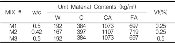
As described in the previous section, volume fraction (Vf) of steel fiber and w/c ratio are considered as two primary factors. A hooked-end steel fiber (DRAMIX 40/30: 30mm length and 0.4mm diameter), which is widely used in practice, was chosen as fiber ingredient. For the purpose of this study, three different types of SFRC mixtures were considered. Table 1 shows the mixture
Effects of Fiber Volume Fraction and Water/Cement Ratio on Toughness Development of Steel Fiber Reinforced Concrete
proportions of the SFRC materials. Type I Portland cement was used as binding matrix, crushed gravel with nominal maximum size of 19mm (3/4 inch) and washed well-graded sand were used as coarse and fine aggregates, respectively. To reduce the variability from fine and coarse aggregates, their ratio was maintained as constant in all mixtures.
Table 1. Mixture Proportions of SFRC MIX # w/c Unit Material Contents (kg/㎥)
Vf(%)
W C CA FA
M1 0.5 192 384 1073 697 0.25
M2 0.42 167 397 1107 719 0.25
M3 0.5 192 384 1073 697 0.5
W: Water, C: Cement, CA: coarse aggregates(25mm max.), FA: fine aggregates, Vf: Volume fraction of fiber
In casting test specimens, to avoid the clumping of fibers that occasionally occurs during mixing[8], the mixing was conducted as follows. First, one-half of the fiber required for the mixture and all other dry materials were dry-mixed for 2 minutes. Then, the water was added and mixed for the next 1 minute. Finally, the other half of fibers for the mixture were added to the mixture and mixed for an additional 2 minutes. The specimens were cast into 105 mm by 150 mm by 525 mm beam molds immediately after finishing the mixing procedure.
The specimens were demolded at the age of 1 day, with the exception of the specimens to be tested at the age of 12 hours. The specimens for tests at the ages of 3, 7, and 28 days were stored in moisture and a temperature controlled room by the time of the test. Two specimens for each mixture were prepared, for a total of 30 specimens (3 mixtures x 2 specimens x 5 test ages).
3.2 Experimental Setup and Test Procedures Figure 1 shows the experimental setup employed in this study. MTS closed-loop testing system was used for the flexure toughness test with the
mid-span deflection as a control signal. All flexure toughness tests were performed according to ASTM C1018 recommendation except for an initial deflection control rate to ensure the safe capture of the first peak load and deflection. Up to the first peak load, the rate of 0.025 (mm/min) was used for the deflection control rate. Immediately after capturing the first peak load, the deflection control rate was automatically changed to a standard rate of 0.050 (mm/min).
Load
150mm
150mm 150mm
150mm
LVDT
75mm 75mm
Figure 1. Specimen dimensions and experimental setup
4. Experimental Results and Discussions
4.1 First Crack Properties
12 hr 1 day 3 days 7 days 28 days
M1 1.48
1.98 8.48
9.41 20.86
21.88 24.99
24.20 31.82 31.75
M2 3.46
2.75 11.56
11.20 23.32
25.66 28.89
31.22 40.13 35.43
M3 2.10
2.15 11.44
10.42 22.45
21.93 27.67
24.42 35.17 32.35 Table 2. First crack load (kN)
The load-deflection curves obtained from the tests are plotted in Figure 2. The first-crack loads and the first-crack deflections were obtained from the load-deflection curves and are shown in Tables 2 and 3, respectively. The flexural strengths of the mixtures at age of 28 days are also listed in Table 4 for a rough estimation of material quality. It is worth noting that Vf used in this study was relatively small, so the first crack load and the peak load are almost identical.
12 hr 1 day 3 days 7 days 28 days
M1 0.025
0.027 0.041
0.028 0.046
0.051 0.050
0.056 0.061 0.077
M2 0.031
0.025 0.038
0.032 0.052
0.045 0.055
0.057 0.071 0.062
M3 0.025
0.030 0.051
0.043 0.056
0.057 0.052
0.056 0.046 0.059
Table 4. Flexural strength (MPa)
M1 M2 M3
4.24.2 5.4
4.7 4.7
4.3
0 10 20 30 40
Load (kN)
M1 (Control, w/c=0.50, Vf=0.25%)
0.5d 1d
3d 7d
28d
0 10 20 30 40
Load(kN)
M2 (w/c=0.42, Vf=0.25%)
0.5d 1d
3d 7d
28d
0 10 20 30 40
0 0.5 1 1.5 2
Load(kN)
Deflection(mm) M3 (w/c=0.50, Vf=0.50%)
0.5d 1d
3d 7d
28d
Figure 2. Load-deflection curve as a function of age
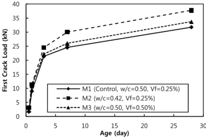
Figure 3 shows the development of the first-crack load of each mixture as a function of
control mixture (M1), both the reduction of w/c ratio (M2) and increment of Vf (M3) increase the first-crack load through the age. The increase of first-crack load due to w/c reduction is an expected behavior, since the first-crack load is directly related to matrix strength of concrete that was enhanced by w/c reduction. The increase of first-crack load due to the Vf increase is not very significant. This is because the absolute amount of Vf (0.5%) is not sufficient to affect the first crack behavior, although the relative amount of Vf is as much as double the control.
Figure 4 shows the first crack deflection of each mixture as a function of age. M1 and M2 specimens (Vf=0.25%) show a similar trend in the first crack deflection through the age, but M3 specimen (Vf =0.5%) shows much better performance in the first crack deflection up to 3 days compared to the other cases. After 3 days, the first crack deflection decreases gradually. This result suggests that the first crack deflection is not proportional to the first crack load in SFRC. But only one type of mixture that has different Vf was tested in this study, so it may not be possible to generalize the trend for Vf > 0.25%. Therefore, an additional test is recommended for future study to confirm that it is a general trend.
0 5 10 15 20 25 30 35 40
0 5 10 15 20 25 30
First Crack Load (kN)
Age (day)
M1 (Control, w/c=0.50, Vf=0.25%) M2 (w/c=0.42, Vf=0.25%) M3 (w/c=0.50, Vf=0.50%)
Figure 3. Development of first-crack load as a function of age
Effects of Fiber Volume Fraction and Water/Cement Ratio on Toughness Development of Steel Fiber Reinforced Concrete
0 0.01 0.02 0.03 0.04 0.05 0.06 0.07 0.08
0 5 10 15 20 25 30
First Crack Deflection (mm)
Age (day)
M1 (Control, w/c=0.50, Vf=0.25%) M2 (w/c=0.42, Vf=0.25%) M3 (w/c=0.50, Vf=0.50%)
Figure 4. Development of first crack deflection
Table 5. First-crack Toughness (kN-mm)
12 hr 1 day 3 days 7 days 28 days
M1 0.023
0.031 0.201
0.171 0.603
0.613 0.704
0.873 1.194 1.618
M2 0.068
0.035 0.342
0.364 0.769
0.685 0.998
1.088 1.646 1.394
M3 0.034
0.040 0.356
0.269 0.786
0.772 0.843
0.898 1.034 1.207
0 0.2 0.4 0.6 0.8 1 1.2 1.4 1.6
0 5 10 15 20 25 30
First Crack Toughness (kN-mm)
Age (day)
M1 (Control, w/c=0.50, Vf=0.25%) M2 (w/c=0.42, Vf=0.25%) M3 (w/c=0.50, Vf=0.50%)
Figure 5. Development of first crack toughness
0 100 200 300 400 500 600 700
0 5 10 15 20 25 30
Flexure Stiffness (kN/mm)
Age (day)
M1 (Control, w/c=0.50, Vf=0.25%) M2 (w/c=0.42, Vf=0.25%) M3 (w/c=0.50, Vf=0.50%)
Figure 6. Development of flexure stiffness
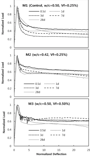
Figure 7. Normalized load-deflection responses
The first crack toughness values for each mixture are listed in Table 5, and development with respect to age is shown in Figure 5. The reduction of the w/c ratio increases the first-crack toughness throughout the age. On the other hand, the increment of Vf tends to increase the first-crack toughness up to the age of 7 days. At the age of 28 days the first-crack toughness of M3 mixture is lower than that of M2 mixture. As described above, this is mainly due to there being a different behavior of the first-crack deflection of M2 mixture, even though the first-crack load of
Figure 6 shows the development of flexure stiffness of each mix as a function of age. The specimens of Vf=0.25% (M1, M2) show a similar trend. Up to the age of 3 days, flexure stiffness increases rapidly. However, after that day, only a small increment of the flexure stiffness is observed.
The mixture of Vf=0.5% (M3) also shows a rapid change of flexure stiffness up to the age of 3 days, but after 3 days a significant increment in flexure stiffness is observed compared to other mixtures. This result suggests that w/c ratio has a small impact on the development of stiffness after the age of 3 days, but Vf affects the development of stiffness of SFRC even after the age of 3 days.
4.2 Relative Post-peak Toughness
Figure 7 shows the normalized load-deflection responses of each mixture at different ages. Each curve in the figure was normalized by the first-crack load and the first-crack deflection. Due to this normalization, the areas underneath the curves up to the normalized deflection of unity are almost identical regardless of mixtures or ages, and thus we can graphically estimate the relative post-peak toughness by comparing the areas underneath the curves after the normalized deflection of unity. Note that this graphical approach is conceptually the same as the toughness indices of ASTM C1018 but is more intuitive, in that we can judge the overall post-peak performance at a glance.
The first observation from the figure is that changing w/c ratio and Vf affects the relative post-peak behavior of load-deflection response.
Both the decrease of w/c (M2) and the increase of Vf (M3) improve the relative flexure toughness through the age. The decrement of the w/c ratio increases the mechanical properties of the binding matrix, thus increasing the bonding strength of
relative post-peak behavior. In case of Vf, the increment of Vf increases the total amount of fiber bridging forces, thus showing better performance in the relative post-peak behavior.
The second observation that can be made based on the figure is that for all mixtures, the relative post-peak toughness at the age of 0.5 days is greater than that at the age of 28 days. In other words, the relative post-peak behavior at later age is more brittle than that at very early age.
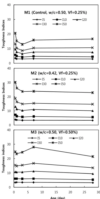
Between 1 and 7 days age, this statement is not that clear, so ASTM C1018 toughness indices were calculated for quantitative analysis. The ASTM C1018 toughness indices are listed in Table 6 and are also shown in Figure 8 as a function of age.
The curves in the same mixture show a similar shape regardless of the index value, and each mixture shows its own trends in the development of toughness indices. The curves for M1 show maximum values of the indices at the age of 0.5 days and decrease until the age of 3 days. After that, the indices increase at the age of 7 days and show small variations at the age of 28 days. The curve for M2 shows a similar trend to M1 but the increment from 3 days to 7 days is much smaller than for M1 mixture. On the other hand, the curves for M3 reach a maximum at age of 7 days and a minimum at age of 28 days.
The common trend regardless of mixture is that toughness development, which is post-peak relative toughness indices, does not show a monotonic increase, as is typical for other mechanical properties such as elastic modulus or compressive strength of concrete. The main reason for this trend is that the indices are defined in a relative manner, so they indicate relative post-peak performance in comparison with the pre-peak performance.
Effects of Fiber Volume Fraction and Water/Cement Ratio on Toughness Development of Steel Fiber Reinforced Concrete
Table 6. ASTMC1018 Flexure Toughness Indices 12 hr 1 day 3 days 7 days 28 days
M1
I5 3.20
3.58 2.88
3.09 2.61
3.19 3.28
2.90 2.87
2.88
I10 5.20 6.11 4.46
5.22 3.81
4.63 4.94
4.53 4.41
4.39
I20 8.66 10.43 7.05
8.53 6.01
6.90 7.66
7.58 7.46
7.53
I30 11.70 14.80 9.44
11.24 8.23
9.01 10.19
10.57 10.65
10.65
I50 17.80 23.34 14.57
15.97 12.67
13.04 15.58
16.10 16.72
16.43
M2
I5 3.42
4.28 3.59
3.57 3.19
3.49 3.35
3.48 3.33
3.28
I10 6.33 8.13 6.12
6.41 5.39
5.99 5.81
6.32 5.71
5.44
I20 11.36 14.69 10.51
12.02 9.85
10.72 10.21
11.79 10.21
9.99
I30 16.25 21.39 15.15
17.56 14.36
15.30 14.45
16.26 14.80
14.60
I50 25.11 35.01 24.05
27.99 22.70
24.48 22.85
24.82 23.23
22.52
M3
I5 3.18
3.45 3.48
3.50 3.17
3.59 3.25
3.62 2.99
3.39
I10 5.74 6.31 5.83
6.14 5.65
6.12 5.41
6.59 4.66
5.90
I20 10.85 10.77 10.23
10.95 10.27
10.98 9.50
12.94 7.86
11.00
I30 16.00 14.95 14.46
15.30 14.89
15.92 13.71
19.72 10.93
16.19
I50 26.43 23.02 22.49
24.16 23.20
25.73 22.27
33.76 16.49
26.24
4.3 Overall Energy Absorption Capacity
The other type of flexure toughness indices relate to the toughness based on overall energy absorption, which is defined as the area underneath the load-deflection curves from zero to a specified value of the deflection. In this study, the deflection of 1.27mm (0.05 inches) was specified for toughness calculation. The toughness indices were calculated from the curves in Figure 2 and listed in Table 7.
0 10 20 30 40
Toughness Indices
M1 (Control, w/c=0.50, Vf=0.25%)
I5 I10 I20
I30 I50
0 10 20 30 40
Toughness Indices
M2 (w/c=0.42, Vf=0.25%)
I5 I10 I20
I30 I50
0 10 20 30 40
0 5 10 15 20 25 30
Toughness indices
Age (day) M3 (w/c=0.50, Vf=0.50%)
I5 I10 I20
I30 I50
Figure 8. ASTM C1018 toughness indices as a function of curing ages
12 hr 1 day 3 days 7 days 28 days
M1 6.71
10.64 31.44
35.29 72.69
69.76 97.05
112.93 147.31 161.86
M2 23.06
20.95 76.27
97.29 149.40
163.02 185.92
213.82 247.87 231.49
M3 16.06
13.21 69.60
64.28 172.13
154.71 157.49
238.99 161.84 237.66 Table 7. Toughness indices up to the deflection of 1.27mm
(0.05in.)
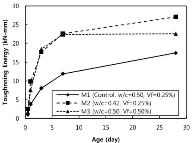
0 5 10 15 20 25
0 5 10 15 20 25 30
Toughnning Energy (kN-mm)
Age (day)
M1 (Control, w/c=0.50, Vf=0.25%) M2 (w/c=0.42, Vf=0.25%) M3 (w/c=0.50, Vf=0.50%)
Figure 9. Toughening energy development up to the deflection of 1.27mm(0.05in.)
0 0.2 0.4 0.6 0.8 1 1.2
0 5 10 15 20 25 30
Normalized Toughness
Age (day)
M1 (Control, w/c=0.50, Vf=0.25%) M2 (w/c=0.42, Vf=0.25%) M3 (w/c=0.50, Vf=0.50%)
Figure 10. Normalized toughness development up the deflection of 1.27mm(0.05in.)
Figure 9 shows the development of flexure toughness for all mixtures as a function of age. As seen in the figure, changing the matrix property (w/c and Vf) affects the toughening performance of the SFRC mixtures. Both M2 (w/c=0.42, Vf=0.25%) and M3 (w/c=0.5, Vf=0.5%) show greater toughness compared to M1 (w/c=0.5, Vf=0.25%) through the age. Better performance for the M2 and M3 mixtures compared to the M1 mixture can be predicted since the matrix properties are enhanced due to the reduction in w/c and increase in Vf.
The decrease of w/c enhanced the mechanical binding strength of the matrix, resulting in better performance, and the increase of Vf increases the
Another noticeable observation in the toughness development among the mixtures is that the rates of toughness development with age are quite different. In Figure 9, the mixture of Vf=0.25%
(M1 and M2) shows gradually increase up to the age of 28d. But the mixture of Vf=0.5% (M3) shows a much faster development rate up to the age of 7d, and no further increase after age of 7d.
This trend is much clearer with the normalized version of the curves, as shown in Figure 10. In this figure, the toughness development curves were normalized by the value of 28 days. The rate of the flexure toughness development for the higher volume mixture (M3) shows the fastest development rate, while that for lower w/c mixture (M2) show the next development rate, and the control mixture (M1) shows the slowest rate of toughness development.
5. Conclusion
Several aging characteristics of SFRC were identified, which were as follows.
The development of toughness with age up to first-crack and that of post-peak have different behaviors. Post-peak toughness of SFRC is obtained at an earlier age than first-crack toughness. This means that the development of residual strength with age is obtained more rapidly compared to that of first-crack strength.
Development of energy absorption capacity (flexure toughness) is similar to that of strength of concrete, as there is a logarithmic relationship between toughness gain and age.
The converging rate of flexure toughness of each mixture toward 28-day value are not identical. The lower w/c ratio shows a faster converging rate, and the higher Vf shows a faster converging rate.
Effects of Fiber Volume Fraction and Water/Cement Ratio on Toughness Development of Steel Fiber Reinforced Concrete
Acknowledgements
The authors wish to acknowledge the support from the Center of Excellence for Airport Technology at University of Illinois and also from Pukyong National University (Grant # : PK-2011-65).
References
1. Ding Y, Kusterle W. Compressive Stress-Strain Relationship of Steel Fiber-Reinforced Concrete at Early Age. Cement and Concrete Research. 2000 Oct;30(10):1573-9.
2. Gopalaratnam VS, Shah SP, Batson GB, Criswell, ME, Ramakrishnan V, Wecharatana M. Fracture Toughness of Fiber Reinforced Concrete. ACI Materials Journal. 1991 Jul;88(4):339-53.
3. Gopalaratnam VS, Gettu R. On the Characterization of Flexural Toughness in Fiber Reinforced Concretes. Cement and Concrete Composites. 1995 Sep;17(3):239-54.
4. Trottier JF, Banthia N. Toughness Characterization of Steel-Fiber Reinforced Concrete. ASCE Journal of Materials in Civil Engineering. 1994 May;6(2):264-89.
5. Balaguru P, Narahari R, Patel M. Flexural Toughness of Steel Fiber Reinforced Concrete. ACI Materials Journal. 1992 Nov;89(6):541-9.
6. Song PS, Hwang S. Mechanical Properties of High-strength Steel Fiber Reinforced Concrete. Construction and Building Materials. 2004 Nov;18(9):669-73.
7. Soroushian P, Bayasi Z. Fiber Type Effects on the Performance of Steel Fiber Reinforced Concrete. ACI Materials Journal. 1991 Mar;88(2):129-34.
8. Chan YW, Li VC. Age Effect on the Characteristics of Fiber/Cement Interfacial Properties. Journal of Material Science. 1997 Oct;32(19):5287-92.
9. Li VC, Chan YW. Determination of Interfacial Debond Mode for Fiber-Reinforced Cementitious Composites. ASCE Journal of Engineering Mechanics. 1994 Apr;120(4):707-19.
10. ASTM International. ASTM C1018 Standard Test Method for Flexural Toughness and First-Crack Strength of Fiber Reinforced Concrete (using beam with third-point loading).
West Conshohocken: American Society of Testing and Materials. 1998. p. 8
11. ASTM International. ASTM C1609 Standard Test Method for Flexural Performance of Fiber Reinforced Concrete (using
beam with third-point loading). West Conshohocken:
American Society of Testing and Materials. 2006. p. 9 12. Japan Concrete Institute. JCI Standards for Test Methods of
Fibre Reinforced Concrete-Method of Test for Flexural Strength and Flexural Toughness of Fibre Reinforced Concrete(Standard SF4). Tokyo: Japan Concrete Institute;
1983. p. 4