Vol. 18, No. 6, pp. 140-145, December 2014
Performance Analysis of WHR-ORC Using Hydrocarbon Mixtures for 20kW Gross Power at Low Temperature
Patricia Kwakye-Boateng*, Jung-In Yoon**†, Chang-Hyo Son***, Kueh Lee Hui**** and Hyeon-Uk Kim***
(Received 27 October 2014, Revised 12 December 2014, Rccepted 02 December 2014)
Abstract: Exploitation of renewable energies is on the increase to mitigate the reliance on fossil fuels and other natural gases with rocketing prices currently due to the depletion of their reserves not to mention their diverse consequences on the environment. Divergently, there are lots of industries
"throwing" heat at higher temperatures as by products into the environment. This waste heat can be recovered through organic Rankine systems and converted to electrical energy with a waste heat recovery organic Rankine cycle system (WHR-ORC). This study uses the annual average condenser effluent from Namhae power plant as heat source and surface seawater as cooling source to analyze a waste heat recovery organic Rankine cycle using the Aspen HYSYS simulation software package.
Hydrocarbon mixtures are employed as working fluid and varied in a ratio of 9:1. Results indicate that Pentane/Isobutane (90/10) mixture is the favorable working fluid for optimizing the waste heat recovery organic Rankine cycle at the set simulation conditions.
Key Words:Condenser Effluent, Hydrocarbons, Organic Rankine Cycle, Waste Heat
**†Jung-In Yoon(corresponding author): Department of Refrigeration and Air Conditioning Engineering, Pukyong National University.
E-mail: [email protected], Tel:051-629-6180
*Patricia Kwakye-Boateng: Graduate School of Refrigeration and Air Conditioning Engineering, Pukyong National University.
***Chang-Hyo Son, Hyeon-Uk Kim: Department of Refrigeration and Air Conditioning Engineering, Pukyong National University.
****Kueh Lee Hui: Department of Electrical Engineering, Dong-A University.
― Nomenclature ―
m : Mass flow rate [kg/h]
Q : Heat [kW]
ORC : Organic Rankine cycle
Subscripts
c : Condenser e : Evaporator p : Pump s : Entropy t : Turbine
1. Introduction
About 20% of the world's population is without electricity with about 9.2% in Africa, over 7.36%
in India and other developing countries. Also, increase in fossil fuel consumption with accompanying price fluctuations, global warming and depleting fossil reserves necessitate a
renewable alternative to sustain electricity demands.
Conversely, in most industrial countries, 40-50%
makes up waste heat with only 15% being recovered and the 85% dumped into the atmosphere. This waste heat can be recovered through organic Rankine systems and the energy from the flue gases converted to electrical energy to counterbalance the energy consumption at the work premises to compensate operating cost1). A waste heat recovery (WHR) organic Rankine cycle (ORC) system employs the principle of the Clausius-Rankine cycle to capture and recycle waste heat from industrial processes to generate electricity using at low to medium temperatures.
2. Waste heat recovery technologies
Waste heat is heat contained in flue gases from industrial actions like fuel combustion and chemical reactions and discarded into the atmosphere at higher temperatures. By considering the quantity, quality, composition, minimum allowable temperature and operating schedules, availability and other logistics of the waste heat source and the stream to which the heat will be transferred much of the heat can be recovered to minimize losses2).
This study will only consider low grade waste heat source as it accounts for more than 50% of the total heat generated in industries and more compatible with heat exchanger materials and practicable with ORC plants for power generation3).
3. Working fluid selection
A suitable selection of the working fluids is a critical factor for achieving an efficient and a safe operation in an organic Rankine cycle (ORC) as each working fluid has its own range of applicability according to its thermo-physical
properties.
A rough methodology of fluid selection can be summarized in order of priority according to 4) as;
a) Defining the working temperature range for the heat source and heat sink;
b) Focusing on fluid environmental and safety concerns (Montreal Protocol);
c) Evaluating thermodynamic properties and determining cycle efficiencies;
A 1MW solar plant ORC module using n-pentane as working fluid provided an efficiency of 20%1).
This study employs a mixture of pentane/hexane and pentane/isobutene since mixtures can allow power generation at a wide temperature range and reduce irreversibilities. Also, hydrocarbons are environmental benign, can save about 36% on energy cost and generally have low operating pressures reducing the pressure on the system.
Although the considered Hydrocarbons are flammable, existing ORC processes at higher temperatures employ R601 as working fluid making it not much of a worry5)]. The mass fractions of the selected working fluids are varied in a ratio of 9:1.
4. System modeling
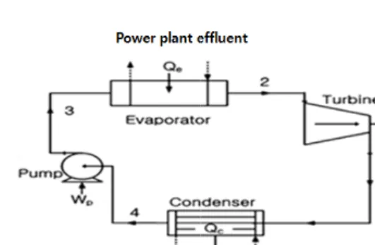
As shown in Fig. 1, the basic components of the WHR-ORC are the evaporator, turbine, condenser
Fig. 1 Schematic diagram of the WHR-ORC 6,7)
Fig. 2 P-h diagram of the WHR-ORC system 6,7)
and a pump. Waste heat from Namhae power plant effluent enters the evaporator to exchange heat with the working fluid. The working fluid leaves as saturated vapor from state 2 and expands in a turbine coupled to a generator to produce power.
It exits at state 1 and enters the condenser to exchange heat with surface sea water at constant pressure. The saturated liquid working fluid then enters the feed pump (state 4) and compressed to the evaporator's subcritical pressure (state 3) to repeat the cycle.
The mathematical model is analyzed as presented in Table 1.
The economic analyzers presented in Table 2 are used to analyze the WHR-ORC in order to help select the most optimized fluid.
As shown in Table 3, the efficiencies of the turbine and pump are fixed within their typical
Table 1 Mathematical analysis of the W HR-ORC
Component Energy
Evaporator Qem
h2h3
Turbine Wt m
h2h1
ηtCondenser Qcm
h1h4
pump Wpm
h3h4
ηp WHR-ORC efficiency:ORC e -
WHR WQ
η
,
WWtWpTable 2 Economic analyzers for the WHR-ORC Economic
Analyzer Deductions
Evaporator Sizing
APRE=Evaporator Capacity/
Gross turbine work Condenser
Sizing
APRC=Condenser Capacity/
Gross turbine work Turbine to
pump ratio
TTP = Gross turbine work/
Pump work
range of applicable efficiencies. The optimization variables for this study are the working fluid evaporator inlet pressure, turbine outlet pressure and the heat exchanger log mean temperature difference. After these factors are fixed the working fluid evaporator inlet mass flow rate is varied until the gross power is 20kW. The fixed variables can be manipulated for optimized system performance as per desired output.
5. Simulation results and discussions
Table 3 Simulation assumptions and inputs
Parameters Inputs
Pump efficiency 65%
Turbine efficiency 80%
Pressure drops
Heat source in evaporator 50kPa Surface seawater in condenser 50kPa Between working fluid and heat
exchangers 10kPa
Log mean temperature difference (LMTD)
Evaporator 3.5oC
Condenser 3.5oC
Temperature variations
Heat source temperature 75oC Change in heat source evaporator inlet and outlet temperature 10oC Cooling source temperature 17oC Change in cooling source condenser inlet and outlet temperature 7oC
Table 4 Evaporator inlet pressures for selected working fluids
Working fluid Evaporator inlet pressure(kPa) Pentane/Hexane (90/10) 248.1 Pentane/Hexane (10/90) 117.4 Pentane/Isobutane (90/10) 327.8 Pentane/Isobutane (10/90) 864.8
The higher the molecular weight the higher the boiling point and molecular weight correlates to density.
Fig.4 Comparison of mass flow rate
Fig. 5 Comparison of TTP
So, the higher the molecular weight the denser
the fluid. From Fig. 4, Pentane/hexane (10/90) mixture showed the highest mass flow rate whilst Pentane/hexane (90/10) recorded the lowest.
Although Pentane/hexane (10/90) has the lowest evaporator inlet pressure. It has the highest molecular weight. Hence, denser than all the mixtures so its high mass flow rate. Albeit Pentane/hexane (90/10), having an evaporator inlet pressure higher than Pentane/Isobutane (90/10) and Pentane/Isobutane (10/90) has a higher molecular weight thus its lowest mass flow rate. Therefore, there exist an indirect relationship between the fluids molecular weight and evaporator inlet pressure.
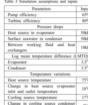
Fig. 6 Comparison of APRE
As shown in Fig.5, Pentane/hexane (10/90) has the highest TTP and Pentane/Isobutane (10/90) the least. TTP shows the performance of the turbine to pump work, that is, the power produced to that consumed. Therefore, a high TTP is desirable.
Isobutane has the lowest boiling point temperature and since boiling point temperature is inversely proportional to volatility, it may have left the turbine with substantial amount of superheat which increased the condenser load and the temperature of the fluid entering the pump thereby increasing pump work while reducing TTP. Thus, the higher the fluid's boiling point temperature, the higher the
TTP.
As depicted in Fig. 6. Pentane/Isobutane (10/90) has the lowest APRE and Pentane/hexane (10/90), the highest. Isobutane has the lowest boiling point temperature among the selected fluids and Pentane/Isobutane (10/90), the lowest molecular weight (density) compared to Pentane/hexane (10/90).
Conversely, the APRE of Pentane/Isobutane (90/10) is 7.4% higher than Pentane/Isobutane (10/90) which is the lowest and 2.2% lower than Pentane/Isobutane (90/10). APRE is a direct indication of the evaporator capacity and a reduction in evaporator inlet vapor density reduces evaporator capacity with a high evaporator capacity corresponding to a high APRE. From Table 2, a lower APRE implies a reduction in evaporator size which is desired to reduce capital cost. Thus, the ideal fluid is Pentane/Isobutane (10/90).
Nevertheless, that higher concentration of pentane in the pentane/hexane mixture reduced the evaporator size than a higher concentration of hexane.
Fig. 7 Comparison of net power for selected working fluids
As seen in Fig. 7, Pentane/hexane (10/90) has the highest net power and Pentane/Isobutane (10/90), the smallest. This result conforms to the
evaporator inlet pressures from Table 4. Turbines convert differential pressure to energy and a larger differential pressure leads to a high energy output.
As such, a low evaporator inlet pressure correlated to a high net power for the dense mixtures.
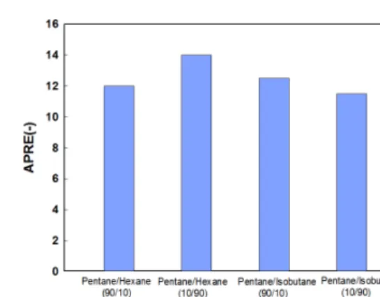
From Fig.8, Pentane/Isobutane (10/90) has the highest efficiency whereas Pentane/hexane (10/90), the least. Unlike net power, high efficiency correlates to low molecular weight and large molecular weights require more energy to vaporize, meaning higher temperatures are essential to induce a phase change. However, just like the APRE and APRE, Pentane/hexane (90/10) has efficiency increment of 2.6% compared to Pentane/Isobutane (90/10).
Fig. 8 Comparison of efficiency
6. Conclusions
Pentane/Isobutane (10/90) mixture recorded the highest efficiency while Pentane/hexane (10/90) mixture has the highest net power. For any WHR-ORC application, the application target is the amount of power which can be recovered yet high system efficiency indicates utilization of the heat source. Thus, it is imperative to select a fluid which offers a balance between net power, components costs as well as tolerable system efficiency as far as optimization of the WHR-ORC
is concerned. Accordingly, Pentane/Isobutane (90/10) is the preferred mixture for optimizing the WHR-ORC.
Acknowledgement
This work was financially supported by the National R&D project of the "Development of Energy utilization technology with Deep Ocean Water" supported by the Korean Ministry of Land, Transport and Maritime Affairs.
References
1. A. Bourji and A. Winstead, 2013, “Optimizing an ORC, American Institute of Chemical Engineers”, CEP, pp. 35-39.
2. S. Devotta and F. A. Holland, 1985,
“Comparison of theoretical Rankine power cycle performance data for 24 working fluids”, Heat Recovery Systems, Vol. 5, pp. 503-510.
3. Johnson I. and Choate W. T, “Waste Heat Recovery: Technologies and Opportunities in the U.S. Industry”, BCS, Inc. http://www1.eere.energ y.gov, 2008, date accessed; 07/11/2013.
4. T.C. Hung, S.K. Wang, C.H. Kuo, B.S. Pei and K.F. Tsai, 2010, “A study of organic working fluids on system efficiency of an ORC using low-grade energy sources”, Energy, Vol. 35, pp.
1403-1411.
5. B. Saleh, G. Koglbauer, M. Wendland and J.
Fischer, 2007, “Working fluids for low-temperat ure organic Rankine cycles”, Energy, Vol. 32,pp.
1210–1221.
6. J.I. Yoon, C.H. Son, S.M. Baek, H.J. Kim, H.S.
Lee , 2014 “Efficiency comparison of subcritical OTEC power cycle using various working fluids”. Heat and Mass Transfer Vol. 50, pp.
985-996
7. J. I. Yoon, C. H. Son, S. M. Baek, B. H. Ye,
H. J. Kim, H. S. Lee, 2014, "Performance characteristics of a high-efficiency R717 OTEC power cycle" Applied Thermal Engineering, Vol.
72, pp.304-308