Vol.18, No.1, (2016), pp.41~45 http://dx.doi.org/10.9714/psac.2016.18.1.041
```
1. INTRODUCTION
Lately, high temperature superconducting (HTS) wires have been widely used in the demonstrations of transmission cables, motors, MAGLEV and other electrical power components, since they benefit from both the higher critical temperature being above the boiling point of liquid nitrogen and the higher critical magnetic field (and critical current density) [1, 2]. However, the HTS magnets have an intrinsically low n-value, and thus cause the persistent current decay in the closed superconducting loop. From this reason, a current charging system, i.e., the superconducting power charging system should be required to keep the stability of the magnetic field. Since some kinds of superconducting power charging systems, which are operated by a pair of superconducting thermal switches inside the cryogenic, such systems produce joint losses and heating infiltration at switches, in addition, the cryogen system is bulkier [3-5].
Recently, the wireless power transfer (WPT) techniques have been drawing a lot of attention, and these techniques are applied to various areas since the power transfer efficiency and the transfer distance of the techniques have been greatly improved. Such a technology classified with
inductive coupling and magnetic resonance coupling method. The inductive coupling requires the coil to be very close (within 1~2 cm) to the object under charge for successful induction. On the other hands, magnetic resonance coupling method becomes a promising candidate for mid-range (within 1~2 m) and high efficiency power transfer [6, 7]. Thus, the WPT technology based on the magnetic resonance coupling method has been expected as a next generation power transfer system for various power applications in order to ensure elec tric safety and convenience. From this point of view, we proposed a novel wireless power charging system for superconducting HTS magnet (WPC4SM) using copper resonance coupling coils.
Since the novel charging system can transfer power from room temperature to cryogen vessel without any connectors, it ensures the electric safety in addition, enables to utilize as a portable charging device in the superconducting power applications such as MAGLEV etc. In this study, we realize the WPC4SM at 20 cm air gap through different shapes' (helix and spiral receiver) copper resonance coupling coil under HTS magnet including rectifying system in laboratory scale. The RF generator of 370 kHz, 500 W is adopted . W e obtained designing parameters and considerations of WPC4SM system for copper receiver through the proto-type experimental investigations.
Performance and analysis of wireless power charging system from room temperature to HTS magnet via strong resonance
coupling method
Y. D. Chung*,a, C. Y. Leeb, S. Y. Leea, T. W. Leea, and J. S. Kima
a Suwon Science College, Kyeonggi-do, Korea
b Korea Railroad Institute, Kyeonggi-do, Korea
(Received 19 February 2016; revised or reviewed 24 March 2016; accepted 25 March 2016)
Abstract
The technology of supplying the electric power by wireless power transfer (WPT) is expected for the next generation power feeding system since it can supply the power to portable devices without any connectors through large air gap. As such a technology based on strongly coupled electromagnetic resonators is possible to deliver the large power and recharge them seamlessly; it has been considered as a noble option to wireless power charging system in the various power applications. Recently, various HTS wires have now been manufactured for demonstrations of transmission cables, motors, MAGLEV, and other electrical power components. However, since the HTS magnets have a lower index n value intrinsically, they are required to be charged from external power system through leads or internal power system. The portable area is limited as well as the cryogen system is bulkier.
Thus, we proposed a novel design of wireless power charging system for superconducting HTS magnet (WPC4SM) based on resonance coupling method. As the novel system makes possible a wireless power charging using copper resonance coupled coils, it enables to portable charging conveniently in the superconducting applications. This paper presented the conceptual design and operating characteristics of WPC4SM using different shapes' copper resonance coil. The proposed system consists of four components; RF generator of 370 kHz, copper resonance coupling coils, impedance matching (IM) subsystem and HTS magnet including rectifier system.
Keywords : Copper antenna, electromagnetic resonance coupling, HTS magnet, wireless power charging system
* Corresponding author: [email protected]
2. MECHANISM OF WIRELESS POWER CHARGING SYSTEM FOR HTS MAGNET
The fundamental principle and structure of a resonance coupled wireless power charging for HTS magnet (WPC4SM) system with two-separate coils are shown in Fig. 1. It consists of a RF power source (Vs), an impedance matching (IM) circuit, a copper transmitting coil (Tx), copper receiving coil (Rx), and a rectifying circuit including HTS load magnet. As the resonance coupling for each coil can’t match due to varying distance, the transmitting wave is reflected back into antenna and then thermal loss is caused. From this reason, to keep stable resonance coupling, the IM subsystem is one of essential devices, which can minimize reflect energy loss and optimize transfer efficiency under varying distance. The transfer efficiency can be expressed by quality factor Q, which is defined by LC resonance ratio. The antenna coil forms a series RL circuit and the Q factor is expressed as:
(1)
Fig. 2 shows the equivalent circuit of the resonance type WPT4SM system. The symbols of L1 and L2 mean the self-inductances of separated antenna (Tx) & receiver (Rx) coils. Capacitors C1 and C2 are employed to keep the coupled degree easily between Tx and Rx coils. Variable inductances LX1 and LX2 are changed to select the resonance frequency of input source corresponding to LC coupled degree in addition, distance of Tx and Rx coils. Mxy and kxy means mutual inductance and coupling coefficient between coupling coils. They are calculated as [8]
Fig. 1. Schematic diagram of wireless power charging for superconducting HTS magnet (WPC4SM) with two-separate resonance coils.
Fig. 2. Equivalent circuit diagram of WPC4SM of Fig.1.
(2)
The efficiency of the power transfer is calculated based on the equivalent circuit. The ratio of power reflection and transmission can be defined by Eq. (3), where S11 and S21 mean reflected wave and transmission wave properties.
Here, S21 can be calculated with Eq. (4) [9], where Z0 means total impedance of the receiver part.
(3)
(4)
3. EXPERIMENTAL RESULTS 3.1. Experimental setup
In this work, we investigated transmitted and rectified characteristics from copper Tx to HTS load magnet based on strong magnetic resonances. The spiral and helix-type copper Rx coils are adopted to examine the absorption ability of transmitting waves for high power. The dimensional and design specifications of Tx and Rx coils
TABLE I
DIMENSIONAL SPECIFICATIONS OF TX AND RX COILS AND HTS MAGNET.
Parameters Dimensions
HTS wire GdBCO (Thickness, width) Ic = 130 A @ 77 K (0.3 mm, 4.5 mm) Inductance of HTS magnet (@ 77K) 1.61 mH
Copper tape coil of Rx coil
(Thickness, width) 0.2 mm, 10 mm
Copper cable coil of Tx coil
(inner diameter, thickness) 9.52 / 0.7 mm Bobbin diameter of Tx coil
Rated Watt of a Bulb
30 cm 30 W Inductance of copper Tx coil (@ 370 KHz) 9.23 µH Inductance of copper Rx coil(Spiral, Helix)
(@ 370 kHz) 8.6, 8.9 µH
Q value of Tx (Cu cable), Rx (Cu tape)
@370kHz 85, 40
(a) Test I (b) Test II Fig. 3. Schematic illustration of experimental sequences for transmission mode including setup for two-separate resonance system.
I2
I1 Antenna,
Tx
Magnetic resonance
Receiver, Rx
(Copper) C1
IM circuit
C2
Vs 370kHz L1
Rectifier circuit Power
transfer
HTS Magnet
(Load) RL
L2 (Copper)
Vs LX1
L1 L2
C2
LHTS
k12
Rx Coil + Rectifier
CY1
LX2
C1
IM Circuit + Tx Coil
Load M12
I1 I2
HTS Load
R fL R
QL 2
y x
xy
xy L L
k M
d=20cm f =370 kHz
Tx coil IM
circuit
Copper (Multi layer,
Helix type)
Rx coil Copper (1 layer, Helix type) Rectifier
HTS Magnet
(%) 100
211 11S
221 100(%)
21S
2 0 2 0
2
2 2
2
0 21
2 1 1
2
C Z L C jZ
L M
S jMZ
Rx
Rx
Rx
Rectifier HTS Magnet
Copper (Spiral type) f =370 kHz
IM Tx
circuit
Copper (Multi layer Helix type)
d=20cm11
Rx
HTS
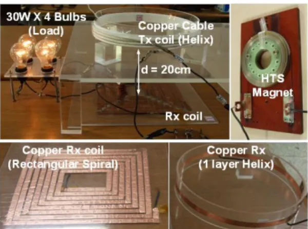
Fig. 4. Photograph of experimental performance of test I with load (bulbs) under input power of 200 W; including fabricated copper Tx coil, Rx coils and HTS magnet.
are shown in Table I. The Rx coil, which is installed on the cover of cooling vessel, is fabricated by copper tape to optimize the installation area. In addition, the copper Rx coil is installed in the room temperature circumstance to minimize the thermal loss due to transferred AC power.
The rectifying circuit, which is connected with HTS magnet, is also installed in company with Rx coil on the cover.
The efficiencies from Tx to Rx and from Tx to HTS including rectifier as shown in Fig. 3 are compared since the energy loss of rectifier including HTS magnet should be considered to optimal design of wireless power charging system.
The rectifying circuit is consists of fundamental full wave rectifier circuit using bridge diode to confirm some specified DC component in the connected HTS magnet.
In the next study, we will fabricate a pair of PCSs with the rectifier circuit to produce pumping current into HTS magnet through persistent current loop. Fig. 3 shows the experimental setup and performance sequences; tests I and II are spiral type one layer rectangular Rx coil and helix type one layer round Rx coil, respectively. The same length and thickness of Rx coils are used. The diameter of the Rx coils is 30 cm. The interval d between Tx and Rx coils is fixed within 20 cm and The RF input power is changed from 100 to 500 W of 370 KHz. To confirm the impedance matching between Tx and Rx coils, the transfer performance is carried out under four bulbs (30 W) load W as shown in Fig. 4. and mean efficiency from power to Rx coil and HTS magnet through IM sub-circuit and Tx coil, respectively. In the next subsection, measured efficiency for Tests I and II is analyzed. To compare transferred power ratio from Test I to II fairly, the reflected power ratio is kept below 1 %.
3.2. Experimental results
In this experiment, the current distributions of Rx and Tx, in addition, rectified current and voltage at HTS load magnet are measured, respectively. Fig. 5 shows the experimental results of current of Tx coil in the input power of 100, 200, 300, 400 and 500 W, respectively. As surely
seen, while the input power is increased, the peak amplitudes of Tx coil at input power of 100, 200, 300, 400 and 500 W are 15.3, 22.1, 27.1, 29.7 and 32, 3 Apeak, respectively. Since the IM subsystem enables to keep strong resonance coupling between Tx and Rx coils, the reflect ratio is fixed below 1 W under tests I and II.
Fig. 6 shows the measured current distributions of spiral shape Rx coil under test I sequence. The transferred peak amplitudes at input power of 100, 200, 300, 400 and 500W are 3.1, 4.7, 5.9, 6.2 and 6.8 Apeak, respectively.
1E-6 2E-6
0.0 3E-6 4E-6
Elapsed time [s]
-40 -30 -20 -10 0 10 20 30 40
Input current at antenna [A]
5E-6 (e)
(a)
Input (e): 500 W Input (d): 400 W Input (c): 300 W Input (b): 200 W Input (a): 100 W Tx coil
Fig. 5. Measured input current of Tx coil under different power conditions.
-9 -6 -3 0 3 6 9
Transferred current at receiver [A]
1E-6 2E-6
0.0 3E-6 4E-6 5E-6
Elapsed time [s]
Rx coil of Test I
(a) (e)
Fig. 6. Measured current of Rx coil of Test I under power conditions of Fig. 5.
0 2 4 6 8
-40 -20 0 20 40 60 80 HTS Magnet of Test I
Rectified current [A] Rectified voltage [V]
1E-6 2E-6
0.0 3E-6 4E-6
Elapsed time [s]
5E-6 (e) (a)
Input (c): 300 W Input (a): 100 W Input (e): 500 W
(e) (a) VRectified
IRectified
Fig. 7. Measured currents and voltages at HTS magnet of Test I through rectifying circuit under power conditions of Fig. 5.
Rx HTS
Apparently, as the input power is increased, the phases of transferred current are gradually shifted. That means the transferred power at Rx coil is reduced corresponding to increasing input power since the loss of reactive power is caused. Fig. 7 shows rectified current and voltage distributions at the HTS magnet through the rectifying system under test I. The rectified currents at input 100, 300 and 500 W are 0.54, 0.86 and 1.01 ADC, respectively.
Additionally, the peak values of rectified voltage at input power of 100, 300, 500 W keep below 10 V, the phase of
Transferred current at receiver [A]
-9 -6 -3 0 3 6 9
1E-6 2E-6
0.0 3E-6 4E-6
Elapsed time [s]
5E-6 Rx coil of Test II (e)
(a)
Fig. 8. Measured current of Rx coil of Test II under power conditions of Fig. 5.
0 2 4 6 8
-40 -20 0 20 40 60 80 HTS Magnet of Test II
Rectified current [A] Rectified voltage [V]
1E-6 2E-6
0.0 3E-6 4E-6
Elapsed time [s]
5E-6
Input (c): 300 W Input (a): 100 W Input (e): 500 W
(a) (e)
(e) VRectified (a)
IRectified
Fig. 9. Measured currents and voltages at HTS magnet of Test II through rectifying circuit under power conditions of Fig. 5.
100 0 20 40 60 80 100
Efficiency [%]
Input Power [W]
of Test I
300 500
Rx HTS
of Test II
Rx
of Test I HTSof Test II
Fig. 10. Measured transfer efficiency of and Tests I and II of marked Fig. 3 below input power of 500 W.
voltage are surely shifted. That means the reactive power loss is caused.
Fig. 8 shows the measured current distributions at one turn helix shape Rx coil under the test II sequence. The input powers of Tx coil are same with Fig. 5. The peak amplitudes of current at Rx coil under input power of 100, 200, 300, 400 and 500W are 4.5, 6.0, 6.8, 7.4, 7.8 Apeak, respectively. As surely seen, since the shift of phase angle between Tx and Rx current keep almost zero, the reactive power losses (reflect loss and thermal loss) is minimized in the Rx coil. Fig. 9 shows rectified current and voltage distributions at the HTS magnet through the rectifying system under test II. The rectified currents at input 100, 300 and 500W are 0.82, 1.32 and 1.72 ADC, respectively. As well as, the peak values of rectified voltages at input power of 100, 300 and 500 W keep below 10 V. The phase shifts of voltage distributions are relatively reduced. Compared with different shapes resonance Tx and Rx coils of test I, the same shapes resonance coils of test II has the advantage of transmission ratio. Under same operating conditions, the transferred current intensity at HTS magnet of test II is distinctly improved over 20 % compared with test I.
Fig. 10 shows measured transfer efficiency and of Tests I and II below input power of 500 W. Apparently, the efficiency until Rx coil of Test II is higher about 8 % than that of Test I. However, the efficiency from input power to HTS magnet through rectifying circuit in Test II is improved about 4 % compared with Test I due to thermal loss of simple full bridge rectifying circuit. In addition, while IM sub-circuit plays a role to keep impedance matching between Tx and Rx coils, it is investigated that it causes thermal loss. Thus, through optimal design of IM sub-circuit and rectifying sub-circuit we will improve the transfer efficiency in the next work.
4. CONCLUSIONS AND DISCUSSIONS
We achieved the novel design of wireless power charging system for HTS magnet using copper resonance coupled coils. The properties and relations for different shapes of Rx coils with varying input power were successfully performed. Especially, we have shown the possibility of power transmission from room temperature to very low temperature combined with rectifying circuit within 20 cm without any current leads. In addition, we examined that the transfer efficiency between spiral and helix types with the same shape coupled coils is apparently improved over 8 %. In this work, since we focus on the comparison between spiral and helix Rx coils, we adopted copper tape coil with low Q value. In the next study, in order to optimize operating loss, we will adopt copper cable with high Q value. In addition, the improved design of rectifying and IM sub-circuit should be investigated in the next. To charge large current, a persistent current switch will be inserted in the HTS magnet in the next. Our research focus is to develop such a wireless charging system to HTS magnet for superconducting power system.
Rx HTS
HTS
ACKNOWLEDGMENT
This work was supported by the Basic Science Research Program through the National Research Foundation of Korea (NRF) funded by Korean Ministry of Education, Science &
Technology (MEST) (Grant: 2015R1D1A1A01058286).
REFERENCES
[1] M. Givoni, “Development and impact of the modern high-speed train: A review,” Transport Rev., vol. 26, no. 5, pp. 593–611, 2006.
[2] M. Igarashi, H. Nakao, M. Terai, T. Kuriyama, S. Hanai, T.
Yamashita, and M. Yamahi, “Persistent current HTS magnet cooled by cryocoler (1)- project overview,” IEEE Trans. Appl. Supercond., vol. 15, no. 2, pp. 1469–1472, 2005.
[3] Y. Iwasa, “HTS magnets; stability; protection; cryogenics;
economics; current stability/protection activities at FBML,”
Cryogenics, vol. 43, pp. 303–316, 2003.
[4] L. J. M. Van de Klundert and H. H. J. ten Kate, “Fully superconducting rectifiers and flux pumps,” Cryogenics, vol. 21, pp.
195–206, 1981.
[5] Y. D. Chung, I. Muta, T. Hoshino, T. Nakamura, and M. H. Sohn,
“Design and performance of compensator for decremental persistent current in HTS magnets using linear type magnetic flux pump,” Cryogenics, vol. 44, no. 11, pp. 839–844, 2004.
[6] A. Kurs, A. Karalis, R. Moffatt, J. D. Joannopoulos, P. Fisher, and M. Soljačić, “Wireless power transfer via strongly coupled magnetic resonances,” Science, vol. 317, no. 5834, pp. 83–86, 2007.
[7] A. Karalis, J. Joannopoulos, and M. Soljačić, “Efficient wireless nonradiative mid-range energy transfer,” Annals of Physics, vol.
323, no. 1, pp. 34–48, 2008.
[8] K. Finkenzeller, RFID Handbook: Fundamentals and applications in contactless smart cards and identification, 2nd ed. New York:
Wiley, 2003, Ch. 4.
[9] D. W. Kim, Y. D. Chung, H. K. Kang, Y. S. Yoon, T. K. Ko,
“Characteristics of contactless power transfer for HTS coil based on electromagnetic resonance coupling,” IEEE Trans. Appl.
Supercond., vol. 22, no. 3, pp. 5400604, 2012.