Fabrication and Mechanical Characteristics of Bulk Nickel/Carbon Nanotube Nanocomposites via the Electrical Explosion of Wire in Liquid
and Spark Plasma Sintering Method
Thuyet-Nguyen Minh, Hai-Nguyen Hong, Won Joo Kim, Ho Yoon Kim, and Jin-Chun Kim*
School of Materials Science and Engineering, University of Ulsan, 93 Daehak-ro, Nam-gu, Ulsan 44610, Korea (Received May 13, 2016; Revised June 13, 2016; Accepted June 15, 2016)
···
Abstract In this study, bulk nickel-carbon nanotube (CNT) nanocomposites are synthesized by a novel method which includes a combination of ultrasonication, electrical explosion of wire in liquid and spark plasma sintering. The mechanical characteristics of the bulk Ni-CNT composites synthesized with CNT contents of 0.7, 1, 3 and 5 wt.% are investigated. X-ray diffraction, optical microscopy and field emission scanning electron microscopy techniques are used to observe the different phases, morphologies and structures of the composite powders as well as the sintered samples.
The obtained results reveal that the as-synthesized composite exhibits substantial enhancement in the microhardness and values more than 140 HV are observed. However an empirical reinforcement limit of 3 wt.% is determined for the CNT content, beyond which, there is no significant improvement in the mechanical properties.
Keywords: Carbon nanotubes, Ni-CNTs nanocomposites, Metal matrix nanocomposites, Electrical explosion of wire method, Spark plasma sintering process
···
1. Introduction
Since discovering [1] and up to now, carbon nanotubes (CNTs) have been considered as an ideal reinforced material to improve the mechanical performance of poly- mers and metals. Due to its outstanding properties such as small diameters and high Young’s modulus, high ten- sile strength and chemical stability, CNTs are promising reinforcements for light weight and high strength com- posites [2, 3]. Nowadays, not only the CNT-reinforced poly- mer matrix composites, but the CNT-reinforced metal matrix composites (MMCs) also are being intensively investi- gated. However, the recent development is shown sepa- rately by each type of material matrix following the order: Aluminium (Al), Cobalt (Co), Copper (Cu), Iron (Fe), Magnesium (Mg), Nickel (Ni) and Titanium (Ti) [4]. In comparison with Al, Cu, Fe and Mg matrix, Ni matrix are not widely used in CNT reinforced MMCs [2, 4, 5]. Most of studies about Ni-CNTs composites was focused on fabrication the thin film or based on Ni-CNT
composite coating but not bulk composites [5]. In some recent studies, nickel is selected as the matrix and the effect of CNT composite on the mechanical characteris- tic is investigated. Ni-CNT composites are usually fabri- cated by coating method to make a thin film or by a powder metallurgy (PM) process or mixing process and then combine with sintering to obtain the bulk samples.
The aim of these processes is offering the possibility of obtaining uniform parts and reducing production costs [6]. Although the results have been reported are good, but there still have the limits of these methods. By using mechanical milling process, a good mixing of CNT com- posite powders could be obtained, but because of a long time milling, the CNT could be damaged and broken down. In case of using molecular-level mixing (MLM) method, there are some researches have been mentioned that this is a unique method of fabricating CNT-metal nanocomposites resulting in a uniform dispersion of CNTs in the metal matrix [7, 8]. However, MLM pro- cess is a costly and complex process with many steps and
*Corresponding Author: Jin-Chun Kim, TEL: +82-52-259-2231, FAX: +82-52-259-1688, E-mail: [email protected]
<PM리뷰>
it has to use some special equipment and chemical solu- tion as well [9].
In this work we present a novel method to fabricate the bulk Ni-CNT nanocomposite via electrical explosion of wire (EEW) and spark plasma sintering (SPS) methods.
The Ni wire is utilized in this study to fabrication Ni nanopowders and to achieve a homogenous dispersion and stability Ni-CNT composite powders. The combina- tion between the colloidal suspension and EEW method uniformly distribute and mix the multiwalled CNTs in the composite powder. In some cases of synthesis the bulk sample of CNTs composite, the CNTs are damaged by high – temperature sintering so in this work the SPS was used in objective to avoid that phenomenon [10, 11]. The influence of the fabrication method of the composite structure, particularly the dispersion of CNT is investi- gated. The influence of combining CNT with Ni matrix on the mechanical properties is also considered.
2. Experimental
The raw materials used in this investigation are a kind of multiwall carbon nanotubes (95%), Fullerene, carbon nanotube, multi-walled, 3-20 nm OD, 1-3 nm ID a length of 0.1-10 µm (Alfa Aesar) and the Ni wire. As for the shape, the bent MWCNTs are intertwined as shows in the Fig. 1. The Ni wire with 0.25 mm in diameter and 27 mm in length (Ssanghee Alloy Co., Ltd) was used for the fabrication of Ni nanoparticle. The EEW in liquid was
used to prepare Ni/CNT nanocomposites. The experimen- tal setup of the EEW process has been described previously [12, 13]. Typical experimental conditions are summarized in Table 1.
To produce the Ni/CNTs composite, the CNTs were dispersed separately in ethanol using ultrasonication method to produce the CNTs dispersion. The CNTs had been ultrasonicated for 1.5 hours with the aim to obtain a homogenous CNTs suspension. Subsequently, the CNTs suspension was used as a working liquid for the prepara- tion of Ni powder by EEW. The number of nickel explo- sion was performed sufficiently to achieve 99.3wt.%, 99wt.%, 97wt.%, and 95 wt.% of nickel that means the contents of CNTs in the obtained Ni-CNTs composites are 0.7wt%, 1wt.%, 3wt.%, and 5wt.% respectively. After the explosion, the Ni powder-coated CNTs nanocompos- ite powders were collected from the suspension via the centrifuge and then by drying at 80oC under vacuum con- dition. A small amount of the as-synthesized nanocomposite powders were taken for the X-ray diffraction (XRD) and Raman spectroscopy analyses. The XRD patterns were recorded from 20o to 90o (2θ) by Rigaku Ultima III x-ray
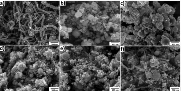
Fig. 1. FE-SEM images of (a) initial CNTs, (b) Ni powder, (c) Ni-0.7wt%CNT, (d) Ni-1wt%CNT, (e) Ni-3wt%CNT and (f) Ni-5 wt%CNT powders.
Table 1. Conditions of the electrical explosion of wire process
Capacitance 30 µF
Charging voltage 30 KV
Ni wire diameter 0.25 mm
Wire length of one explosion 40 mm
Ambient liquid Ethanol
diffractometer (The Woodlands, TX). Raman spectros- copy meansurements were conducted using a Nicolet Almega AR Dispersive Raman Spectrometer (Waltham, MA) with and excitation wave length of 532 nm. The Ni- CNTs nanocomposite powders were then consolidated by a spark plasma sintering (SPS) machine (Mod. 115S, Sumitomo Coal Mining Co.Ltd., Japan). The composite powder (2 gram) was placed in a graphite die with an inner diameter of (10 mm). Subsequently, the sintering conditions are set at a heating rate of 50oC/min with a holding time of 10 minutes and under a constant uniax- ial pressure of 50 MPa in vacuum condition. The com- posites are sintered within the sintering temperature range of 900-1100oC. The density of the sintered composite samples was measured by the Archimedes method. The microhardness was measured with a Leica Vickers micro- indenter with an indentation load 100 g for 15s. In order to obtain a statistical distribution which reliably depicts the hardness of the sample, 10 measurements were per- formed on each sample.
3. Results and Discussions
Fig. 1 shows the FE-SEM images of CNTs, Ni powder and Ni-CNTs powders. It can be seen that the morphol- ogy and structure of the CNTs as characterized in literature [14-16]. The diameter of the initial CNTs is approximately in the range of 30-60 nm (the maximum which was examined is 58 nm). In the shape of the CNTs, there is a conspicuous tendency of agglomeration in the CNTs as seen in the Fig. 1(a). In fact, the CNTs have a high aspect ratio, high flexibility and strong attractive forces, there- fore it leads to a strong tendency to form bundles. How- ever, by using sonication method a very effective technology for dispersing, the CNTs could be dispersed in ethanol solution and the agglomerated of CNTs was separated.
Furthermore, because of the ultrasonically generated shear forces and micro turbulences ultrasound can assist in the surface coating and chemical reaction of nanotubes with other materials [17, 18]. This effect is useful for synthe- sis the Ni-CNTs composite in the next process in this study. Even so, it is the fact that the dispersion time is needed to be controlled because with a long-time disper- sion, the amount of defects apparently increased in CNTs [19, 20] Therefore, in this study the sonication treatment
time was set at 1.5 hours as was mentioned on the exper- imental part.
The morphology of Ni powder and Ni-CNTs compos- ite powders with the contents of CNTs from 0.7wt.% to 5wt.% are figured out in Fig. 1(b), 1(c), 1(d), 1(e), and 1(f). In case of fabrication of Ni in EEW process, Ni wire was exploded in a liquid solution and in this study, ethanol was used as an ambient liquid in this process. As shown in Fig. 1(b) the achieved Ni powders were nearly spherical in shape and aggregates or clusters. An esti- mated of the average size of particles from FE-SEM image lies in the range of a few nanometers to ~ 100 nm.
The particle size distribution is in the range of 20 nm to 90 nm. However, we cannot say that all the wire was exploded perfectly and converted into nanozised parti- cles, because from the Fig. 1(b) we can see and also con- firm that, a number of submicron-sized powders still exist in the fabrication of Ni powders.
For synthesis of Ni-CNTs composites powder, Ni wire was exploded in the CNTs dispersion which was pre- pared by dispersing CNTs in ethanol solution. By this way, the Ni powders which had just generated from the explosion zone of wire could contact with CNTs and bond together and diffuse into the solvent. In addition, under the effect of explosion phenomenon, the liquid ambient was always stirred resulting in homogenous col- loid of the Ni-CNTs. The morphology results illustrate that the CNTs were separated and distributed on the sur- face of the Ni particles homogeneously.
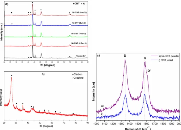
The XRD patterns for the CNTs, the Ni powder and the as-synthesized Ni-CNTs composite powders are given out in Fig. 2. The XRD pattern for the CNTs in Fig. 2(b) shows peaks of two phases, carbon phase with the strong peak corresponding to the (002) planes at 26.03 of 2è angles and graphite phase with the weak peaks. The XRD for the Ni powder not only shows peaks corre- sponding to the (111), (200), and (220) crystallographic planes but also exhibits some weak peaks of nickel.
However, it is easy to recognize that most peaks could not be assigned. It can be explained that during the explo- sion time carbon and oxygen atoms in the ethanol sol- vent are thought to have been integrated in the Ni crystal structure to form metastable phases.
The XRD patterns of the Ni-CNTs composite powders in Fig. 2(a) show that the phases of nickel in the obtained
Ni-CNTs composite powders are totally resemble those in the nickel powders. In addition, the presence of a weak peak of carbon which could be observed when the con-
tents of CNTs are 3wt% and 5wt% confirms the pres- ence of carbon nanotube in the composite powders.
Furthermore, to demonstrate the presence of CNTs the Fig. 2. XRD patterns of the obtained (a) Ni powder, Ni-CNTs composite powders, (b) CNTs and (c) Raman spectra of CNTs and Ni-CNTs composite powder.
Fig. 3. Surface fracture of SPSed composite samples at 900oC: a) Ni-CNT 0.7wt.%; b) 1wt.%; c) 3wt.%; and d) 5wt.%.
Raman spectroscopy was employed. Raman spectra of the CNTs and Ni-CNTs composite powder is shown in Fig. 2(c). The spectrum of the initial CNT shows pri- mary peaks at ~1346, ~1574, and small shoulder peak
~1611 cm−1 wave numbers corresponding to the D, G and D’ bands, respectively. The position of these peaks is the same in case of Ni-CNTs composite powder. This result confirms again the presence of CNTs and also demonstrates that there is no significant change in tex-
ture resulting from the introduction of CNTs in the com- posite powders.
The as-obtained Ni-CNTs powders were sintered by using SPS machine at 900oC, 1000oC and 1100oC to obtain bulk samples. The properties of the achieved bulk samples were observed. To evaluate the sintering pro- cess, the microstructural and surface fracture of the SPSed samples was examined.
The surface fracture of SPSed samples at 900oC is
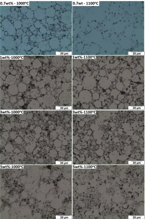
Fig. 4. The optical microstructure of SPSed samples at 1000oC and 1100oC.
shown in Fig. 3. It seems that at 900oC the sintering did not occur, so that the Ni particles and CNTs are distin- guished easily. The bonding between Ni and CNTs is weak, therefore at this temperature the samples were only compressed by the loading force. Because of that, in this part we mainly focus on the SPSed samples which were sintered at 1000oC and 1100oC.
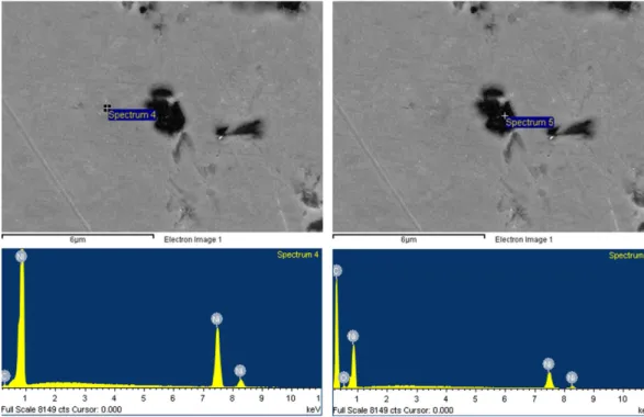
Fig. 4 shows the optical microscopic images of bulk samples of Ni-CNTs composites with the contents of CNTs from 0.7wt.% to 5wt.% after sintering at different temperatures for a 10 minutes holding time. When the sintering temperature was changed from 1000oC to 11000C it is seen that in all samples within the Ni matrix, their presents to be a uniformly distributed second phase or maybe porosity. However, from the EDS results as given out in Fig. 5, it illustrates that the dark regions (spectrum 5) correspond to the bundles of the CNTs but not porosity. The optical microstructures also show that with the increasing of the CNTs content the more agglomeration of CNTs was observed as a result. In addi- tion, as had been defined above the CNTs were distrib- uted and bonded to the surface of Ni powders therefore after sintering process the CNTs were dispensed and maintained at the grain boundary in the sintered samples as shows in the Fig. 4. Come along to this point it could
be anticipated that the distribution of the CNTs not only helps in grain refinement by possibly inhibiting grain growth and providing a nucleation site for new grains during recrystallization in sintering process but result in increase in the mechanical properties of the bulk sam- ples. In fact, the effects of CNTs on the microstructural refinement on the hardness have been demonstrated in some previous researches [21]. Even though increasing the content of CNTs also lead to the formation of poros-
Fig. 5. EDS profiles of the dark region and white region in a Ni-CNTs composite after sintering.
Fig. 6. The density of SPSed samples at different temperature and with different content of CNTs.
ity in the bulk sample [6, 21].
The relation between the sintering parameters and the density of the SPS sintered body of Ni-CNT composites are shown in Fig. 6. The steep slope in Fig. 6 shows that the density of the SPSed samples is depended on the sin- tering temperature and the content of CNTs as well. At 900oC the sintering did not take place so the density of the samples is very low. As the temperature increases to 1000oC and 1100oC, the transport of mass in the sample had been occurring, therefore the particles bond together and lead to increase in density. However, with the high CNT content composites is noticeable for the decrease in the density. Especially, for the 5wt.% CNT composite, the density is the lowest value as compared to that of 0.7 -3wt.%CNT, the cause for the low density of the 5wt.%CNT composite is thought to be the effect of the sintering obstruction by the CNTs.
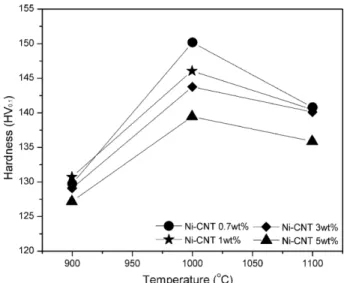
Fig. 7 shows the relation between the sintering parame- ters and the microhardness of the SPS sintered body of Ni-CNT composites. It could be seen that, for each sam- ple of Ni-CNT composite, the hardness of those is depend on the temperature in the sintering process.
Indeed, at 900oC all the samples show a low hardness value due to the weak bonding between particles which is the result of the not completed sintering. When the tem- perature was increased from 900oC to 1100oC the hard- ness also increased and reached the highest value at 1000oC and slightly reduced at 1100oC.
For the 0.7wt.%, 1wt.% and 3wt.%CNT SPSed com-
posites, the hardness of them are almost higher than 140HV at 1000oC. Especially, in case of the 0.7wt%CNT the hardness value is up to 150HV (at 1000oC). However, after the sintering temperature was increased to 1100oC, the hardness of these composites is nearly equal to 140HV. For the 5wt%CNT composite, the hardness value is 139 HV at 1000oC and 135HV at 1100oC. This result is quite lower as compared to that of the 0.7-3wt%CNT composite, this illustrates that with the increased in CNT content up to 5wt.% the effect of the CNT on the hard- ness of the composite is reduced. The increasing in the hardness to the highest value at 1000oC and reducing a bit to get the value of about 140 HV for the 0.7- 3wt.%CNT composites and about 135HV in case of the 5wt.%CNT composite figures out that the high value of hardness at 1000oC is a temporary hardness because at that temperature, the sintering was not completed. After sintering at 1100oC the hardness of these samples is slightly lower than that at 1000oC but the hardness is the same and stable for the 0.7-3wt.%CNT composites (about 140HV) so that we can determine that the sinter- ing could be completed at 1100oC for the Ni-CNTs com- posites in this study. To compare these results with the results which have been reported in some previous researches on this subject it is easy found out that, the hardness of Ni-CNTs composites in this study are higher 5HV than that in previous studies [9, 18, 21].
4. Conclusions
Ni-CNTs nanocomposites were prepared by ultrasoni- cation and EEW in liquid. The carbon nanotubes were dispersed and then distributed and coated on the surface of the Ni powders. Because of that, after sintering pro- cess, the distribution of the CNTs was mainly at the grain boundary in the SPSed composite samples, leading to the inhibition growing of the grain size.
The obtained composites exhibited a substantial enhance- ment in microhardness to more than 140 HV. This result is even higher than as compared to some studies have been published before. However an empirical reinforce- ment limit has been determined for CNTs up to 3wt%.
When the content of the CNTs was increased to 5wt.%, no significant improvement in mechanical properties is observed. The reduction of reinforcing effect is mainly Fig. 7. The density of sintered body as a function of sintering
temperature and the content of CNT.
generated by the reagglomeration of CNTs due to the high weight fraction.
Acknowledgements
This work (S2184829) was financially supported by the Small and Medium Business Administration, Korea.
References
[1] IIjima S: Nature., 354 (1991) 56.
[2] S. R. Bakshi, D. Lahiri, R. R. Patel and A. Agarwal: Thin Solid Films., 518 (2010) 1703
[3] J.N. Boland and X.S. Li: Materials., 3 (2010) 1390.
[4] Nuno Silvestre: Int. J. Compos. Mater., 3 (2013) 28.
[5] S. R. Bakshi, D. Lahiri and A. Agarwal: Int. Mater. Rev., 55 (2010) 41.
[6] S. Yamanaka, R. Gonda, A. Kawasaki, H. Sakamoto, Y.
Mekuchi, M. Kun and T. Tsukada: Mater. Trans., 48 (2007) 2506.
[7] S. Cha, K. K., S. Arshad, C. Mo and S. Hong: Adv. Mater., 70 (2005) 1377.
[8] J. Y. Hwang, B. K. Lim, J. Tiley, R. Banerijee and S. H.
Hong: Carbon., 57 (2013) 282.
[9] T. Borkar, J. Hwang, J. Y. Hwang, T. W. Scharf, J. Tiley,
S. H. Hong and R. Banerijee: J. Mater. Res.,, 29 (2014) 761.
[10] T. Borkar and R. Banerjee: Mater. Sci. Eng., A, 618 (2014) 176.
[11] N. Saheb, Z. Iqbal, A. Khalil, A. S. Hakeem, N. Al Aqeeli, T.
Laoui, A. Al-Qutub and R. Kirchner: J. Nanomater., 2012 (2012) 13.
[12] L. H. Bac, J. S. Kim and J. C. Kim: Res. Chem. Intermed., 36 (2010) 795.
[13] L. H. Bac, Y. S. Kwon, J. S. Kim, Y. I. Lee and J. C. Kim:
Mater. Res. Bull., 45 (2010) 352.
[14] H. W. Kroto, J. R. Heath, S. C. Obrien, R. F. Curl and R.
E. Smalley: Nature., 318 (1985) 162.
[15] D. Ugarte: Nature, 359 (1992) 707.
[16] M. Zeiger, N. Jackel, M. Asian, D. Weingarth and V. Presser:
Carbon., 84 (2015) 584.
[17] A.Koshio, M.Yudasaka, M. Zhang and S. Iijima: Nano Lett., 1 (2001) 361.
[18] J. Zhu, M. Yudasaka, M. F. Zhang and S. Iijima: J. Phys.
Chem. B, 108 (2004) 11317.
[19] A. S. Muhsan, F. Ahmad, N.M. Mohamed and M. R.
Raza: Int. J. Powder Metall., 51 (2015) 57.
[20] A. S. Muhsan, F. Ahmad, N. M. Mohamed, P. S. M. M.
Yusoff and M. R. Raza: Nanosci. Nanotechnol. Lett., 6 (2014) 865.
[21] Suarez, S., F. Lasserre and F. Mucklich: Mater. Sci. Eng., A, 587 (2013) 381.