Development Study of A Precooled Turbojet Engine for Flight Demonstration
Tetsuya Sato*, Hideyuki Taguchi†, Hiroaiki Kobayashi†, Takayuki Kojima†, Katsuyoshi Fukiba†, Daisaku Masaki†, Keiichi Okai†, Kazuhisa Fujita†, Motoyuki Hongoh† and Shujiro Sawai†,
Waseda University* and Japan Aerospace Exploration Agency† 3-4-1 Okubo, Shinjuku, Tokyo 169-8555, JAPAN*
Keywords: Propulsion, Precooled Turbojet, TBCC
Abstract
This paper presents the development status of a subscale precooled turbojet engine “S-engine” for the hypersonic cruiser and space place. S-engine employs the precooled-cycle using liquid hydrogen as fuel and coolant. It has 23 cm x 23 cm of rectangular cross section, 2.6 m of the overall length and about 100 kg of the target weight employing composite materials for a variable-geometry rectangular air-intake and nozzle. The design thrust and specific impulse at sea- level-static (SLS) are 1.2 kN and 2,000 sec respectively.
After the system design and component tests, a prototype engine made of metal was manufactured and provided for the system firing test using gaseous hydrogen in March 2007. The core engine performance could be verified in this test. The second firing test using liquid hydrogen was conducted in October 2007. The engine, fuel supplying system and control system for the next flight test were used in this test. We verified the engine start-up sequence, compressor-turbine matching and performance of system and components.
A flight test of S-engine is to be conducted by the Balloon-based Operation Vehicle (BOV) at Taiki town in Hokkaido in October 2008. The vehicle is about 5 m in length, 0.55 m in diameter and 500 kg in weight. The vehicle is dropped from an altitude of 40 km by a high-altitude observation balloon. After 40 second free-fall, the vehicle pulls up and S-engine operates for 60 seconds up to Mach 2. High altitude tests of the engine components corresponding to the BOV flight condition are also conducted.
Introduction
A turbine-based combined cycle (TBCC) is one of the most promising candidates for the propulsion system for low cost, high reliability and routine access to space and for the hypersonic air-cruiser. Figure 1 shows a roadmap of the TBCC engine development performed by Japan Aerospace Exploration Agency (JAXA). A precooled-cycle turbojet engine (PCTJ) was proposed and a sub-scale engine (S-engine) has been developed since 2004 with reflecting key technologies built by the development study of the ATREX engine (Expander cycle Air Turbo Ramjet engine)(1). PCTJ can operate from take-off to Mach 6 at 26 km of altitude continuously without mode transition.
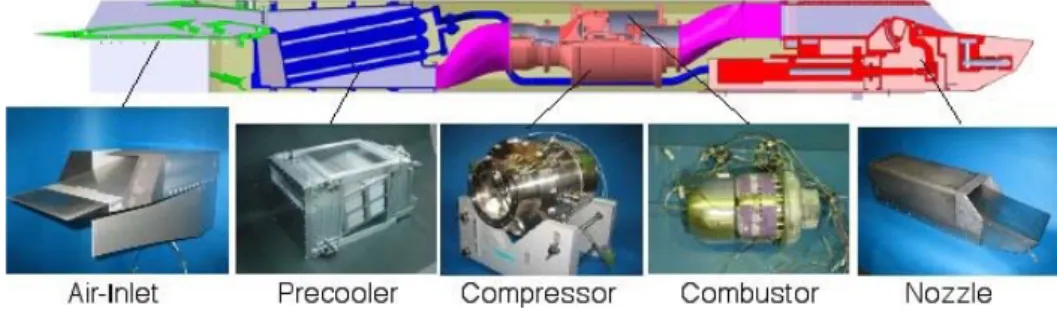
Fig. 1 Roadmap of the TBCC development in JAXA The aerodynamic design and component tests have been finished using wind tunnel models such as an air-intake, precooler, compressor, combustor and nozzle(2). A prototype engine made of metal for the BOV flight demonstration up to Mach 2 is now under development shown in Fig. 2. System firing tests under the sea-level-static condition were conducted in March and October of 2007. These tests verified the precooled system and component performance and healthiness, start-up and acceleration control
Fig. 2 Cross-section of subscale engine (S-engine)
sequences. The BOV flight demonstration will be conducted in 2008.
As the next step, high enthalpy wind tunnel tests corresponding to Mach 4 to 6 conditions are planned.
S-engine will be modified to endure the aerodynamic heating by using carbon based composite materials.
After that, a hypersonic demonstrator will be developed to verify all systems. Several universities are collaborating on this project with JAXA.
In this paper, the present status of the development study of S-engine and its Mach 2 flight test plan using a high-altitude balloon are discussed.
Description of S-engine
A trade-off analysis was performed between two candidates: ATREX and PCTJ from some viewpoints of the performance, present technology level and development easiness. As a result of the analysis, PCTJ was selected mainly because of its better performance at low Mach number. ATREX makes best use of characteristics of liquid hydrogen as fuel and low temperature heat source and is also suitable in the viewpoint of reusability by its system simplicity and lightweight. However, its engine performance depends heavily on the inlet temperature of the turbine, which was supposed to be heated by a C/C composite heat exchanger. The present technology level of the C/C heat exchanger has not been enough matured yet.
We conducted the detailed design of a full-scale PCTJ engine such as optimizing of the engine specification, system feasibility study, weight estimation and engine installation and interference with the vehicle.
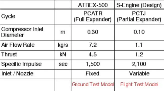
A subscale engine “S-engine” is designed for verifying the cycle and for building fundamental technologies by using actual hardware with reasonable costs. Main dimension and performance of S-engine are listed in Table 1 compared with ATREX-500 (ATREX demonstration engine tested in JAXA). S- engine has 23 cm x 23 cm of rectangular cross section, 2.2 m in overall length and about 100 kg in weight. S- engine produces 1.2 kN of thrust at SLS, which corresponds to a quarter of the ATREX engine. This size was determined to match the Ramjet Engine Test Facility (RJTF) at Kakuda Research Center in JAXA where the Mach 4 to 6 tests will be conducted.
Table 1. Specifications of ATREX-500 and S-engine
S-engine consists of an air-intake, precooler, core-engine, afterburner, nozzle and connecting ducts to demonstrate the overall engine system under the wide flight range from sea-level-static to Mach 6. The engine cycle has been designed using a parametric optimization study. A three-dimensional CAD tool is used for the detailed design and mass estimation.
Air-intake
A rectangular shape air-intake was selected for S- engine because it has higher throat height and simpler variable mechanism for changing the contraction ratio compared with the axisymmetric shape. The air-intake has three ramps and the second and third ramps are variable to make the appropriate shock pattern according to the flight Mach number. Most of a driving load of the ramps is cancelled each other. Its front geometry is 23 cm in width and 7.5 cm in height and the throat height changes from 3.75 cm (at SLS) to 0.60 cm (at Mach 6). The inner flow passage was designed by CFD and modified by the wind tunnel test results. The total pressure recovery at Mach 2 and Mach 5 is 82 % and 21 % respectively. The cross- section area of the air-intake is about half of the engine envelope. So, the lower half is embedded in the body to reduce engine external drag. A prototype air- intake model made of Al-alloy will be manufactured in 2005 FY for the first test flight at Mach 2, which should be partially replaced by composite materials for the Mach 5 flight condition.
Precooler
The main role of the precooler is to cool down the incoming air below 720 K that is the limit of the compressor temperature. It also improves the engine thrust and specific impulse. The precooler is a shell- and-tube type heat exchanger using liquid hydrogen as coolant, which is similar to the ATREX precooler. It has a rectangular shape to match the air-intake and is composed of 1,296 stainless steel tubes of 320 mm in length, 2mm in outer diameter, and 0.15 mm in wall thickness. The precooler is connected to the compressor via a S-shape duct whose cross-sectional form changes from rectangular shape to circle. In order to minimize the airflow distortion on the entrance surface of the compressor, the S-shape duct was designed by CFD. The flight-model precooler whose casing is made of Al-alloy was tested using liquid hydrogen at SLS in 2005. The overall heat exchange rate agrees the design value, which is about 120 kW with the maximum temperature distortion of 40 K. Total pressure losses on the air side and on the hydrogen side are 4 % and 6 % respectively, which satisfy the system requirement.
One of the critical problems on the precooler is the frost formation on its tube surface. The present model avoids the critical frost problem by enlargement of the space between tubes. Some fundamental researches have been conducted to solve this problem fundamentally. Recently, a method has been researched that uses the air-jet supplied from the exit of the compressor to blow off the frost physically.
An experimental and numerical study was also conducted to estimate an amount of the frost accumulated on the precooler(3). It is found that the mass flux is much lower than the conventional theoretical value estimated by Sherwood number when the tube surface temperature is below 220 K.
This is because the theoretical value does not include the effect of the condensation of the vapor to the mist.
This tendency is also simulated by the calculation including the condensation model where the mist is moved by thermophoretic force.
The precooler will be tested to verify the durability and reliability up to Mach 6 condition, that is, the incoming air temperature of 1,655 K.
Core engine
The core engine of S-engine composed by a compressor, combustor and turbine has several requirements such as to be small, light weight and to correspond to the wide flight envelope. A peculiar configuration, which is a simple structure with a diagonal-flow compressor and a single–stage axial flow turbine, was selected instead of more complicated multi-spool structure suitable for the practical large engine.
Mass flow rate, rotational speed and pressure ratio of the design point of the compressor are 1.1 kg/s, 80,000 rpm and 6.0 respectively. Single stage rotor has splitters to prevent the boundary layer separation.
Two stage stators are employed to match the high pressure ratio. A CFD analysis using the modified Daws code indicates 81 % of adiabatic efficiency at the design point. The performance is not similar to that of the axial compressor but to that of the centrifugal compressor. A prototype model made of heat resistance Ti-alloy was manufactured and its rotating test is in progress. A water-cooled DC motor whose maximum power and rotating speed is about 2 kW and 100,000 rpm is used as a starter. The compressor model was tested in the vacuum chamber in ISAS/JAXA, which simulates very low-pressure conditions from the sea-level atmosphere pressure to 1 kPa. Objectives of this low-pressure test are to demonstrate the balloon based flight test at the high altitude and to make higher mechanical rotational speed by reducing the compressor work. The starter could drive the compressor more than 50,000 rpm. A flow-plug valve located at the rear end of the test model regulates the mass flow rate. The test result shows that the P-Q map shrinks (that means the pressure ratio and mass flow rate are lower than that at the design pressure) when the ambient pressure is low because of the thick boundary layer. When the ambient pressure is 1 kPa, the pressure ratio and corrected flow rate decrease by 10 % and 40 % respectively compared with the atmosphere pressure.
A reverse-flow annular-type combustor was selected in order to reduce the total length of the core engine. A radial-injection pre-mixer is introduced to accomplish the combustion in the limited volume.
Combustion tests using the gaseous hydrogen fuel were performed under the actual flight conditions. The
test result shows the temperature rise after the combustor agrees well with the design value under the equivalence ratio of 0.1 – 0.3. The performance on the total pressure loss also satisfies the design requirement.
No structural problems occurred during the tests. An ignition and flame-holding test under the high altitude condition was conducted at Akiruno Testing Center of JAXA as shown in Fig.3. Gaseous hydrogen is supplied to the combustor connected with the chamber whose pressure is preset. It is judged by a temperature rise whether the ignition occurred or not. The test result is shown in Fig. 4. The condition of the BOV flight test is indicated as the area put between the red and blue lines which show in case of 100 % and 60%
of the compressor rotating speed. Marks “O” and “X”
means success and failure of the ignition respectively.
The repeatability is satisfied in the test. The test result shows the ignition cannot be successful in the original flight conditions. Some measures are discussing such as change of the igniter position, addition of the pilot burner and/or change of the flight trajectory.
Fig. 3 Apparatus of the ignition test of the combustion chamber under the low-pressure conditions
Fig. 4 Result of the combustor test
A single stage turbine was designed by CFD whose mass flow rate, pressure ratio and power of the design point are 1.1 kg/s, 2.4 and 250 kW respectively.
The turbine is placed inside of the combustor and the tip speed is about 350 m/s. The maximum temperature
is limited to 1223 K for no cooled turbine. The performance of the turbine was simulated only by CFD without component tests and a prototype model was directly tested in the system firing test.
Afterburner and nozzle
A single-ramp rectangular plug nozzle connected after an afterburner was designed for S-engine. The throat area is adjusted by moving the pear-shape part according to the flight Mach number. As the nozzle and afterburner are exposed by more than 2,000 K, the wall is added a cooling passage cooled by the fuel hydrogen and the nozzle tip is made of composite material. As for the BOV flight test, total heat input is about 230 kW, in which 60 g/sec of hydrogen gas is required to keep the temperature of the nozzle wall less than 1150 K. The supplied hydrogen gas is finally burnt in the afterburner with the air-rich combustion gas. The prototype model with a water-cooling system was tested to verify the thermal fluid performance.
System firing test
Two series of the ground system firing tests of S- engine were conducted at Noshiro Testing Center of JAXA step by step. The first test series called “PCTJ- 1” was conducted in March 2007 as shown in Fig.5.
In this test, we could check almost all of engine components which were newly manufactured.
Especially, it is the most important objective to get data on the power balance between the compressor and turbine. The “work-share” style test was conducted as shown in Fig. 6. The compressor and turbine are connected mechanically by a shaft but the air passed through the compressor and the gas passed through the turbine is independent. The air passed through the compressor is exhausted to the compressor exhaust duct. A pressure-regulating valve located in the compressor exhaust duct controls the back pressure of the compressor. An emergency valve is also set in the duct and quickly opened when the sign of the surging is detected. The turbine is driven by the combustion gas whose air and gaseous hydrogen is from the external air tank and gas cylinders. Some problems were detected on the rotation measurement when the precooler was cooled and on the starter. Maximum rotational speed of 70,000 rpm was attained in this test series.
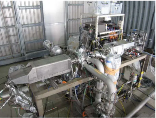
The second test series called “PCTJ-2” was conducted in October of 2007 as shown in Fig.7. The overall engine system with the aerodynamic fairing, hydrogen supply system and control system were built and tested, which is the same as the systems of the flight model. Figure 8 shows the system flow chart on the hydrogen supply. LH2 is supplied to two combustion chambers: the core engine combustor and afterburner. About 8 g/s of hydrogen vaporized by an evaporator is supplied to the core engine combustor as keeping lean combustion. Before the test using LH2, gaseous hydrogen (GH2) is supplied to the core engine combustor to build the steady state start-up sequence. About 52 g/s of LH2 is supplied to the
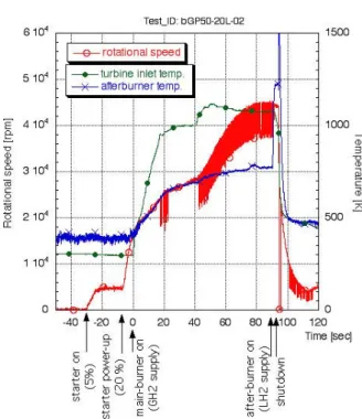
afterburner through the precooler and the cooling wall of the nozzle to keep rich combustion. One of the test results is shown in Fig. 9. The compressor is driven up to 16,000 rpm (20 % of the design speed) by the starter. After that, GH2 is supplied to the core engine combustor to accelerate the turbine with keeping the turbine inlet temperature below 1223 K. After the engine reaches the steady state, LH2 is supplied to the precooler and afterburner. The compressor-turbine matching was pretty well and the way of the start-up sequence was obtained by the GH2 test. The precooler and afterburner worked well. The problems occurred in the PCTJ-1 were solved in the PCTJ-2. However, the start-up sequence using LH2 has not been constructed yet. The equipment of the supply, control and measurement system for the flight test was well verified in this test.
Fig. 5 System firing test (PCTJ-1)
Fig. 6 Work share style core-engine
Fig. 7 System firing test (PCTJ-2)
Fig. 8 Route of hydrogen supply
Fig. 9 Test result (PCTJ-2)
Engine flight demonstration by a balloon based operation vehicle (BOV)
As the low cost flight way of S-engine, we proposed the Balloon based Operation Vehicle (BOV)
(4) using a high altitude observation balloon “B-300”
developed in ISAS/JAXA. A schematic drawing of the vehicle installing S-engine is shown in Fig. 10. The
vehicle mainly made of CFRP is approximately 5m in length, 0.55 m in diameter and 500 kg in weight. A main wing and movable tail wings controls the vehicle attitude.
Originally, BOV was proposed as a test bed for micro gravity experiments for more than 30 seconds.
The vehicle is separated from the balloon and falls freely. 12 cold gas jet thrusters control to keep the micro gravity condition by compensating the aerodynamic drag. The flight schedule of BOV is listed in Table 2. From 2005 to 2009, 4 vehicles are launched step by step and the S-engine flight demonstration will be conducted by the third one
“BOV-3” in 2008. BOV-1 and BOV-2 were successfully tested as shown in Fig 11, which could demonstrate the core components and control system as well as the microgravity tests. About 15 seconds and 30 seconds of micro-gravity conditions were attained in each test. The vehicles recovered on the sea after decelerating by parachutes from the supersonic speed.
The vehicle of BOV-3 is much different from that of others. S-engine is installed to the bottom of the winged vehicle. A LH2 tank and supply valves are located instead of a microgravity test module. A main wing is equipped to pull up the vehicle. CFD analyses with the wind tunnel tests help the design of the vehicle configuration.
Fig. 10 Schematic drawing of BOV with S-engine Table 2 Flight schedule of BOV
Type Wings Engine
1 A ! !
Demonstration of core components & control system
05/2006
2 B Equipped !
Demonstration of total system for microgravity experiment
05/2007
3 C Equipped Equipped Flight test of S-engine 10/2008 4 B Equipped ! Microgravity experiments
open for common users 2009
No Configuration Purpose of flight Date
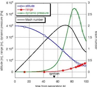
The original flight trajectory is shown in Fig.12.
The vehicle is launched at the balloon center newly constructed in Taiki town in Hokkaido and lifted up to an altitude of 40 km by the balloon. After the separation from the balloon, the vehicle falls freely for 40 seconds. Then, the vehicle pulls up and S-engine is
fired when the dynamic pressure is enough for ignition.
Duration of the engine firing test is about 1 minute.
Maximum dynamic pressure and velocity are 55 kPa and Mach 2.0 respectively. The vehicle is decelerated by 3-stage parachutes from the supersonic speed and recovered on the sea.
Fig. 11 BOV-1 launched by the balloon
Fig. 12 Flight trajectory of BOV-3
Development of the hypersonic turbojet experimental vehicle (HYTEX)
We intend advanced flight tests using balloons under the higher Mach number conditions following the flight campaign of BOV. The vehicle, dropped off from the balloon like BOV, is accelerated to Mach 5 by an additional solid motor or HAN (Hydroxyl Ammonium Nitrate) thruster developed in JAXA. The small HAN thruster is to be tested on the BOV-3 experiment.
The hypersonic turbojet experimental vehicle (HYTEX) installing S-engine has also been designed and researched(5). The configuration is designed by an
integrated optimization analysis on the aerodynamics and trajectory. The flat-shaped vehicle whose length is 4.5 m installed 1 or 2 sets of S-engine. Several seconds of the Mach 5 cruise by using auxiliary acceleration devices such as a high altitude balloon and/or solid rocket as shown in Fig.13. Aerodynamic performance of the vehicle has been analyzed by the CFD and by the subsonic, supersonic and hypersonic wind tunnel tests. The results show the L/D ratio of the vehicle is about 3 at Mach 5.
Fig. 13 Hypersonic turbojet experimental vehicle (HYTEX)
Conclusion
The precooled turbojet engine operating up to Mach 6 has been proposed for the future hypersonic aeroplane and TSTO spaceplane system. Through the development study of ATREX, several innovative technologies were built and feasibility of the TSTO system was displayed. As the next step, development of the subscale flight engine ‘S-engine’ is in progress.
Demonstration tests under SLS, Mach 2 and Mach 5 conditions will be conducted step by step.
References
1) Tanatsugu, N., Sato, T., Naruo, Y., et al. : Development Study on ATREX Engine, Acta Astronautica, 40, 1996, pp. 165-170.
2) Sato, T., Taguchi, H., Kobayashi, H.,Kojima, T.,Okai, K.,Fujita, K. and Masaki, D.:
Development Study of the Mach 6 Turbojet Engine, Asian Joint Conference on Propulsion and Power, Beijing, 2006.
3) Fukiba, K., Sato, T., Tsuboi, N. and Kobayashi, H.: Mass Transfer around a Cold Cylinder with Condensation of Vapor (1st Report) ̶ Mass Flux Decrease Due to Condensation of Vapor at Surface Temperatures from 200 to 250 K ̶ , Transactions of JSASS, 50(169), 2007, 151-159.
4) Fujita, K., Sawai, S., Kobayashi, et al. : Precooled turbojet engine flight experiment using balloon- based operation vehicle, Acta Astronautica, 59(1- 5), 2006, pp.263-270.
5) Tsuchiya, T., Takenaka, Y and Taguchi, H.:
Multidisciplinary Design Optimization for Hypersonic Experimental Vehicle, AIAA Journal, 45(12), 2007, pp.3021-3023.