This paper explains the fatigue test for a composite train carbody. The composite carbody with
length of 23m was manufactured as a sandwich structure composed of a aluminium honeycomb core
and woven fabric carbon/epoxy face. In order to evaluate fatigue strength of the composite
carbody, the carbody was excited by two 50-ton capacity hydraulic actuators. The excitation
frequency was determined by natural frequency evaluation test under full weight condition. The
test was conducted for 2x10 6 cycles. During the fatigue test, fatigue cracks of the composite
carbody and steel underframe were inspected by the nondestructive tests using X-ray and liquid
penetrant. From test tests, no fatigue crack was detected.
23030mm 15900mm
3690mm
2970mm
HVAC system Observation window
Side entrance door
Stainless steel underframe Window Area
Roof
Inner frame Aluminum honeycomb
sandwich with carbon/epoxy face
Inner frame of sidewalls Inner frame of roof structure
Joining area between composite bodyshell and
underframe CF1263
carbon/epoxy
CF1263 carbon/epoxy Aluminum
honeycomb
(a) Dimension of the tilting train. (b) Cross sectional view of the composite carbody.
Fig. 1 Hybrid composite carbody for Korean tilting train.
Fig. 2 Installation of the composite carbody for fatigue test. Fig. 3 Hydraulic actuator for excitation.
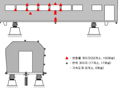
: 변형률 게이지(53개소, 100채널) : 변위 게이지 (17개소, 17채널) : 가속도계 (6개소, 6채널)
Fig. 4 Schematic diagram of the installation locations of each sensor.
Fig. 5 The installed sensors on the
carbody.
Frequency (Hz)
1 2 3 4 5
Load (kN)
-60 -40 -20 0 20 40 60
3.4 Hz Actuator #1
Fig. 6 Dynamic signal of the hydraulic actuator.
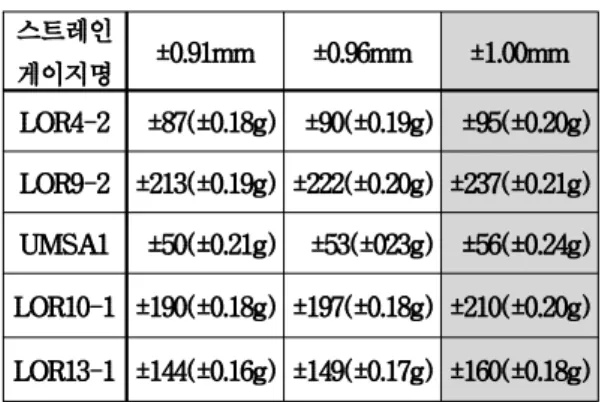
Table 1 Strain and deflections according to the displacement of actuator.
Fig. 7 Locations inspected by X-ray. Fig. 8 X-ray device.
Load (kgf)
0 5000 10000 15000 20000 25000 30000
St ra in ( με )
-1000 -500 0 500 1000
LOR10-1 LOR10-2 LOR10-3 LOR11-1 LOR11-2 LOR11-3 LOR12-1 LOR12-2 LOR12-3 LOR13-1 LOR13-2 LOR13-3 Applied air-con. weight
Fig. 9 The measured strains according to the applied load.
Load (kgf)
0 5000 10000 15000 20000 25000 30000
D e fle c tio n ( m m )
-40 -20 0 20 40
D#1 D#2 D#3 D#4 D#5 D#6 D#7 D#8 D#9 D#10 D#11 D#12 D#13 D#14 D#15 D#16 D#17 Applied air-con. weight