Effect of Reaction Temperature on the Geometry of Carbon Coils Formed by SF
6Flow Incorporation in C
2H
2and H
2Source Gases
Sung-Hoon Kim*
Department of Engineering in Energy & Applied Chemistry, Silla University, Busan 617-736, Korea (Received December 26, 2011, Revised January 26, 2012, Accepted January 27, 2012)
Carbon coils could be synthesized on nickel catalyst layer-deposited silicon oxide substrate using C2H2 and H2 as source gases and SF6 as an additive gas under thermal chemical vapor deposition system. The geometries of as-grown carbon materials were investigated with increasing the reaction temperature as the increment of 25oC from 650oC up to 800oC. At 650oC, the embryos for carbon coils were formed. With increasing the reaction temperature to 700oC, the coil-type geometries were developed. Further increasing the reaction temperature to 775oC, the development of wave-like nano-sized coils, instead of nano-sized coils, and occasional appearance of micro-sized carbon coils could be observed. Fluorine in SF6 additive may shrink the micro-sized coil diameter via the reduction of Ni catalyst size by fluorine’s etching role. Finally, the preparation of the micro-sized carbon coils having the smaller coil diameters, compared with the previously reported ones, could be possible using SF6 additive.
Keywords : Carbon coil, SF6, Geometry, Reaction temperature, Thermal chemical vapor deposition
I. Introduction
Since the first report by Davis et al. carbon coils have been noticed because of their unique shape [1].
Carbon coils have spring-like helix-shaped geometry.
Therefore they may induce an electrical current and consequently generate a magnetic field. So, electrical, magnetic and mechanical properties of carbon coils are more attractive for electromagnetism than strai- ght ones [2]. Their predicted electrical, magnetic and mechanical properties might be attractive to use as nano/micro-sized tactile sensors, actuators, reso- nators, mechanical springs, and so on [3-6].
Coils-type geometries were also reported using SiC [7,8] and Si3N4 [9-12]. However, the production of coils-type geometry was accidental and lack of reproducibility. Furthermore, the electrical proper- ties of helically coiled geometry may have metallic, semiconducting or semi-metallic depending on their geometry including diameter [13]. Therefore the con- trolled geometry of carbon coils would be the problem to be addressed in order to achieve the controlled electrical properties of carbon coils.
For the catalyst, In and Sn were known to play an important role for the formation of carbon coils [14-16]. Co-silica or Fe-silica catalysts have been
(b) (c) (a)
Figure 1. Schematic diagram of experimental setup of (a) thermal evaporator system, (b) plasma enhanced chem- ical vapor deposition system, and (c) thermal chemical vapor deposition system.
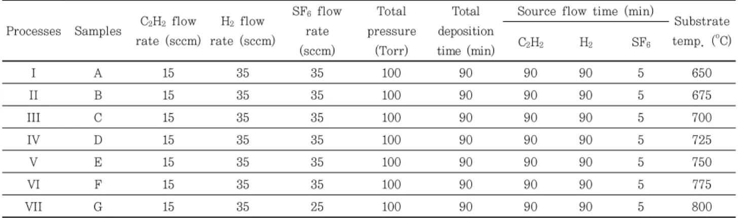
Table 1. Experimental conditions for the deposition of carbon coils on the substrates for sample A∼G.
Processes Samples C2H2 flow rate (sccm)
H2 flow rate (sccm)
SF6 flow rate (sccm)
Total pressure
(Torr)
Total deposition time (min)
Source flow time (min)
Substrate temp. (oC) C2H2 H2 SF6
I A 15 35 35 100 90 90 90 5 650
II B 15 35 35 100 90 90 90 5 675
III C 15 35 35 100 90 90 90 5 700
IV D 15 35 35 100 90 90 90 5 725
V E 15 35 35 100 90 90 90 5 750
VI F 15 35 35 100 90 90 90 5 775
VII G 15 35 25 100 90 90 90 5 800
served as substrates for the preparation of carbon coils by catalytic pyrolysis of acetylene [17]. In general, iron-family catalysts (Fe, Co, and Ni) were noticed for use in the synthesis of carbon coils. Among them, es- pecially Ni was known as an effective catalyst for the formation of the super elastic carbon coils [18].
Motojima et al. first reported the regularly mi- cro-coiled carbon fibers with high reproducibility by the catalytic pyrolysis of acetylene containing a small amount of sulfur impurity, and reported the prepara- tion conditions and morphologies [19-21]. Sulfur im- purities were mostly incorporated in the form of hy- drogen sulfide (H2S), carbon disulfide (CS2), and thi- ophene (C4H4S) [22-26]. Sulfur-related species are very hazardous for environment and inevitably dam- age the health of the people in surroundings. So, their use should be reduced in the synthesis of carbon coils as possible as one can.
In our previous work, we chose SF6 as a relatively
safe sulfur impurity and reduced the amount of the incorporated SF6 gas by minimizing the injection time [27]. In this work, we varied the reaction temperature and examined the growth patterns and morphologies of the carbon coils formed by 5 min-SF6 flow in- corporation in C2H2 and H2 source gases.
II. Experimental
The SiO2 substrates in this work were prepared by the thermal oxidation of the 2.0×2.0 cm2 p-type Si (100) substrates. The thickness of silicon oxide (SiO2) layer on Si substrate was estimated about 300 nm. A 0.1 mg Ni powder (99.7%) was evaporated for 1 min to form the Ni catalyst layer on the substrate using thermal evaporator as shown in Fig. 1a.
Prior to carbon coils deposition, Ni-coated sub- strate was placed in the plasma enhanced chemical
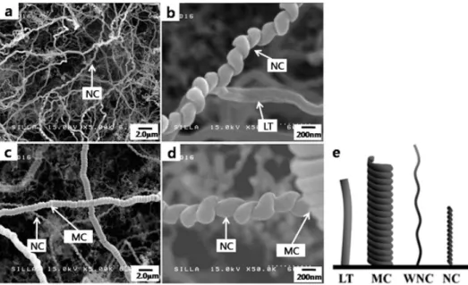
Figure 3. (a) FESEM images for sample C, (b) the high-magnified FESEM images for sample C, (c) FESEM images for sample D, and (d) the high-magnified FESEM images for sample D, and (e) the generally accepted four geometrical categories of carbon coils, namely linear tub (LT), micro-sized coil (MC), nano-sized coil (NC), and wave-like nano-sized coil (WNC).
Figure 2. (a) FESEM images for sample A, (b) the high-magnified FESEM images for sample A, (c) FESEM images for sample B, and (d) the high-magnified FESEM images for sample B.
vapor deposition (PECVD) system as shown in Fig. 1b.
H2 gas was introduced into PECVD chamber and then the substrate was pre-cleaned for 5 minutes using H2
plasma. After H2 plasma reaction, the thickness of Ni catalyst layer was measured about 100 nm by inves- tigating the cross section of Ni catalyst layer de-
posited substrate using field emission scanning elec- tron microscopy (FESEM).
For carbon coils deposition, thermal chemical vapor deposition (TCVD) system was employed as shown in Fig. 1c. C2H2 and H2 were used as source gases. SF6, as an incorporated additive gas, was injected into the reactor during the reaction. The flow rate for C2H2
and H2, were fixed at 15 and 35 standard cm3 per mi- nute (sccm), respectively. SF6 flow rate and injection time were set as 35 and 5 minutes, respectively.
According to the different reaction processes, the re- action temperatures were varied as the increment of 25oC from 650oC up to 800oC. The detailed reaction conditions were shown in Table 1. Morphologies of carbon coils-deposited samples were investigated us- ing FESEM.
III. Results and discussion
Fig. 2 shows FESEM images showing the surface morphologies of samples A and B at the reaction
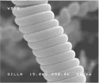
Figure 4. Representative FESEM image of the regular micro-sized coil (MC) obtained at 725oC.
Figure 5. (a) FESEM images for sample E, (b) the high-magnified FESEM images for sample E, (c) FESEM images for sample F, and (d) the high-magnified FESEM images for sample F.
Figure 6. (a) FESEM images for sample G and (b) the high-magnified FESEM images for sample G.
temperature of 650oC and 675oC, respectively. Indeed, the CNFs formation density seems to be not much different according to the position on the sample. It reveals the uniformly distributed CNFs in whole area for the sample. The uniformly distribution phenom- ena of carbon materials formation according to the samples A∼G could be clearly and repeatedly observed. The high-magnified FESEM images reveal
the embryo for CNFs formation on sample A (Fig. 2b) and the immature CNFs on sample B (Fig. 2d).
Fig. 3 shows FESEM images showing the surface morphologies of samples C and D at the reaction temperature of 700oC and 725oC, respectively. In this case, the CNFs geometry having conventional linear type and nano-sized coil-type could be clearly ob- served at 700oC (Fig. 3b). In general, many types of carbon coils-related geometries could be observed on sample surfaces, so they could be usually classified into four geometrical categories, namely linear type (LT), micro-sized coil (MC), nano-sized coil (NC), and wave-like nano-sized coil (WNC) (Fig. 3e). At 725oC, NC could be mostly observed and the occa- sional appearance of MC could be also observed as shown in Figs. 3c and d. This result reveals the oc- currence of geometry change from NC and LT to NC and MC with increasing the reaction temperature from 700oC to 725oC. Representative FESEM image of the regular MC obtained at 725oC are shown in Fig. 4.
This regular carbon coil has constant coil pitch of
~0.2 μm without any coil gap and have coil diameter of ~0.8 μm. In some reports [24], the carbon fila- ments in the carbon coils have a flat type edge shape.
However, our case the edge shape was a circular type as shown in Fig. 4.
Further increasing the reaction temperature up to 775oC, the appearance of WNC and the occasional de- velopment of MC could be clearly observed as shown in Fig. 5. Indeed, the number density of MC was highest at 750oC. Indeed WNC type geometries, in-
stead of NC, were mostly observed in this temper- ature range. At the highest reaction temperature (800oC) in this work, we could find WNC as the prev- alent coil structure with the occasional appearance of MC as shown in Fig. 6a. Comparing the images be- tween Fig. 5d with Fig. 6b, the diameters of WNC was increased from ~150 nm to ~250 nm. Based on above results, we suggest the geometry development of car- bon coils as embryos → NC → NC with MC → WNC with MC with increasing the reaction temperature from 650oC up to 800oC.
In this work, diameters of the micro-sized carbon coils and the composed carbon nanofilaments are on average 10 μm and 0.2 μm, respectively. The length of the coil are in the range between a few micro- meters and a few tens micrometers. The dependence of the coil diameters of micro-sized carbon coils on the reaction temperature is negligible. However, the diameter of carbon nanofilaments seems to be in- creased at the highest temperature (800oC) in this work. Compared with the previous result by Chen and Motojima [24], this results show slightly different phenomena. Chen reported about 10 μm and 0.5 μm sizes of micro-sized coil diameter and coil pitch, re- spectively in thiophene additive and C2H2/H2 source gases system. In addition, they showed the strong dependence of the micro-sized coil diameter and morphologies on the reaction temperature from 700oC to 870oC. At this time, we understood the dependence difference of the micro-sized coil diameter with the temperature, compared with Chen’s result, may be due to the different reaction temperature range with different additive and injection time. Meanwhile, the size difference of the micro coils seems to be due to the fluorine’s etching ability in SF6 additive. It was reported that the growth mechanism of the mi- cro-sized carbon coils in which the driving force of the coiling of the carbon nanofilaments to form the micro-sized carbon coils is an anisotropic deposition on the carbons from the respective Ni catalyst faces
[28]. Therefore fluorine in SF6 additive may shrink the micro-sized coil diameter via the reduction of Ni catalyst size by fluorine’s etching role. Although the exact causes and the detailed mechanism for the dif- ference of micro-sized coils diameter for our results, compared with the previous reported ones, couldn’t be fully understood at this time, we could reduce the micro-sized coil diameter by incorporation SF6
additive. Consequently this work may provide the preparation of the micro-sized carbon coils having the smaller coil diameters, compare with the pre- viously reported ones.
IV. Conclusion
The geometry of carbon coils were developed as embryos → NC → NC with MC → WNC with MC with increasing the reaction temperature from 650oC up to 800oC. Fluorine in SF6 additive may shrink the mi- cro-sized coil diameter via the reduction of Ni cata- lyst size by fluorine’s etching role. Finally, the prep- aration of the carbon micro coils having the smaller coil diameters, compared with the previously reported ones, could be possible using SF6 additive.
References
[1] W. R. Davis, R. J. Slawson, and G. R. Rigby, Nature, 171, 756 (1953).
[2] S. Ihara and S. Itoh, Carbon 33, 931. (1995) [3] A. L. M. Reddy, R. I. Jafri, N. Jha, S. Ramaprabhu,
and P. M. Ajayan J. Mater. Chem, 21, 16103 (2011).
[4] S. Ihara and S. Itoh, Carbon, 33, 931 (1995).
[5] L. J. Pan, T. Hayashida, M. Zhang, and Y.
Nakayama, Jpn. J. Appl. Phys. 40, L235 (2001).
[6] S. Amelinckx, X. B. Zhang, D. Bernaerts, X. F.
Zhang, V. Ivanov, and J. B. Nagy, Science, 265,
635 (1994).
[7] S. Yang, X. Chen, S. Motojima, and H. Iwanaga, J.Nanosci. Nanotechnol. 4, 167 (2007).
[8] A. Addamiano. J Cryst Growth, 617, 617 (1982).
[9] S. Motojima, T. Hamamoto, and H. Iwanaga. J Cryst Growth, 158, 79 (1996).
[10] S. Motojima, S. Ueno, T. Hattori, and K. Goto.
Appl Phys Lett, 54, 1001 (1989).
[11] S. Motojima, S. Ueno, T. Hattori, and H. Iwanaga.
J Cryst Growth, 96, 383 (1989).
[12] S. Motojima, T. Yamana, T. Araki, and H.
Iwanaga. J Electrochem Soc, 142, 3141 (1995).
[13] U. Vogt, H. Hofmann, and V. Kramer. Key Eng Mater, 89-91, 29 (1994).
[14] K. Akagi, R. Tamura, and M. Tsukada, Phys. Rev.
Lett. 74, 2307 (1995).
[15] M. Zang and Y. Nakayama, and L. J. Pan, Jpn.
J. Appl. Phys. 39, L1242 (2000).
[16] R. Kanada, L. J. Pan, S. Akita, N. Okazaki, K.
Hirahara, and Y. Nakayama, Jpn. J. Appl. Phys.
47, 1949 (2008).
[17] W. Wang, K. Yang, J. Gaillard, P. R. Bandaru, and A. M. Rao, Advanced Materials 20, 179 (2008).
[18] K. Hernadi, A. Fonseca, J. B. Nagy, D. Bernaerts, and A. A. Lucas, Carbon 34, 1249 (1996).
[19] W. In-Hwang, H. Yanagida, and S. Motojima, Mater. Letters 43, 11 (2000).
[20] S. Motojima, Y. Itoh, S. Asakura, and H. Iwanaga, J. Mater. Sci. 30, 5049 (1995).
[21] X. Chen and S. Motojima, J. Mater. Sci. 34, 5519 (1999) .
[22] S. Motojima, S. Asakura, T. Kasemura, S.
Takeuchi, and H. Iwanaga, Carbon 34, 289 (1996).
[23] S. Motojima, Y. Itoh, S. Asakura, and H. Iwanaga, J. Mater. Sci. 30, 5049 (1995).
[24] X. Chen, T. Saito, M. Kusunoki, and S. Motojima, J. Mater. Res. 14, 4329 (1999).
[25] X. Chen and S. Motojima, Carbon 37, 1817 (1999).
[26] X. Chen and S. Motojima, J. Mater. Sci. 34, 5519 (1999).
[27] S. Motojima, S. Asakura, T. Kasemura, S. Takeuchi, and H. Iwanaga, Carbon 34, 289 (1996).
[28] S. -H. Kim, J. Korean Vacuum. Soc. 20, 374 (2011).
[29] M. Kawaguchi, K. Nozaki, S. Motojima, and H.
Iwanaga, J. Cryst. Growth. 118, 309 (1992).
SF
6-C
2H
2-H
2기체에 의해 생성된 탄소 코일 기하구조의 반응온도 효과
김 성 훈*
신라대학교 에너지응용화학과, 부산 617-736
(2011년 12월 26일 받음, 2012년 1월 26일 수정, 2012년 1월 27일 확정)
니켈촉매 막을 증착시킨 산화규소 기판위에 아세틸렌기체와 수소기체를 원료로, 육불화황기체를 첨가기체로 열화학기상증착 시스템하에서 탄소코일을 증착하였다. 반응온도를 650oC에서 800oC까지 증가시키면서 증착된 탄소 코일의 기하구조를 조사하 였다. 650oC에서는 주로 탄소나노필라멘트 형성의 전단계가 나타났으며, 반응온도가 증가하자(700oC) 나노 크기의 코일들이 나타났다. 775oC로 반응온도를 더욱 증가시키자, 파도물결과 같은 나노 코일들이 성장되었으며, 간혹 마이크로 크기의 코일들 도 나타났다. 육불화황에 첨가된 불소의 에칭효과로 니켈 촉매의 크기를 줄일 수 있을 것으로 여겨지며, 따라서 육불화항 첨가 기체의 사용으로 기존에 보고된 것보다 작은 크기의 직경을 갖는 마이크로 탄소 코일을 얻을 수 있었다.
주제어 : 탄소 코일, 육불화항, 기하구조, 반응온도, 열화학기상증착
* [전자우편] [email protected]