입자연마가공에서의 입자 형상의 영향에 대한 고찰
김동균·성인하
*
†한남대학교 대학원 기계공학과
*
한남대학교 기계공학과A Closer Look at the Effect of Particle Shape on Machined Surface at Abrasive Machining
Dong Geun Kim and In-Ha Sung *†
Graduate School of Hannam University, Dept. of Mechanical Engineering
* Dept. of Mechanical Engineering, Hannam University
(Received April 2, 2010; Revised May 13, 2010; Accepted June 5, 2010)
Abstract −
Despite the increasing need of nanometer-scale accuracy in abrasive machining using ultrasmall par- ticles such as abrasive jet and chemical mechanical polishing(CMP), the process mechanism is still unknown.
Based on the background, research on the effects of various process parameters on the machined surface at abra- sive machining was motivated and performed by using finite element analysis where the effect of slurry fluid flow involved. The effect of particle shape on the machined surface during particle-surface collision was dis- cussed in this paper. The results from FEA simulation revealed that any damage or defect generation on machined surface by the impact may occur only if the particle has enough impact energy. Therefore, it could be concluded that generation of the defects and damage on the wafer surface after CMP process was mainly due to direct contact of the 3 bodies, i.e., pad-particle-wafer.
Keywords −
abrasive particle(
연마입자), chemical-mechanical polishing(CMP,
기계-
화학적연마가공), finite element analysis(FEA,
유한요소해석)
1. 서 론
연마제트가공
(abrasive jet machining),
폴리싱(polishing)
등마이크로
/
나노 입자를이용한연마가공은잔류응력 및열영향부(heat-affected zone)
등가공변질층이 거의 발생하지 않으며,
미세가공 및 초미세형상구현,
높은치수정밀도 및 우수한표면거칠기를 얻을 수있는 등 다양한 장점으로 인해 광학부품
,
반도체 메모리 제조등에폭넓게사용되어오고있다
[1-3].
이러한공정들에서는일반적으로슬러리
(slurry)
유체와함께SiO
2, Al
2O
3또는
CeO
2의연마입자가 고속으로분사되어공작물의가공표면에 충격을 가하거나 또는 슬러리 연마입자와
공작물표면이 패드 등과
3
개체접촉(3-body contact)
을 이루면서기계적연마및화학적작용이복합적으로발 생하여 재료가 제거된다.
다양한 공정변수의 영향 및연마메커니즘의규명을위해많은연구가수행되어왔 으나 입자에의한 연마 메커니즘은그 중요성에도 불 구하고공정의복잡성과여러변수들의복합적인영향 등으로아직까지도 명확하게 밝혀져있지 않다
.
특히,
반도체웨이퍼
(wafer)
평탄화를위한기계-
화학적연마공정
(Chemical Mechanical Polishing, CMP)
은 공정후에 표면에 발생하는 여러 형태의
micro-scratch
가device
의 수율 및신뢰성에 큰영향을 미치게되는데,
이러한
micro-scratch
의발생원인및메커니즘도명확히규명되어있지않아현업에서도이의발생억제를위
†주저자·책임저자 :
[email protected]
한적절한대응방안을수립하지못하고있는상황이다
.
미세입자
-
표면간접촉,
충돌에대한 보다 근본적인이해와메커니즘규명을위하여컴퓨터시뮬레이션해 석및원자현미경을이용한실험등다양한연구가진 행되어왔다
.
접촉역학적 접근을통해 연마입자의 충돌
,
스크래치(scratch)
나패드표면의요철(asperity)
에의 한가공표면의응력해석[4-7]
에대한연구가이루어져왔으며
,
입자의충돌각과속도가가공표면에발생하는 가공형상인 크레이터(crater)
의 모양에 미치는 영향에 대한유한요소해석 연구에서는작은충돌각및속도 에서는 예측모델이 잘 맞지 않음을제시하면서 입자 형상과크기,
마찰조건등이 더중요한요인이될 것으로예측하고있다
[1].
마이크로스케일 동역학 모델
(micro-scale dynamic
model, MSDM)
을이용한연구에서는연성재료와취성재료에대해최대재료제거량
(erosion loss)
이나타나는 입자의충돌각이각각30
도및90
도로다르게나타남을보여주고있다
[8].
이와같이,
유한요소나분자동역학을이용한시뮬레이션연구들은다양한결과와분석 을제시하고있으나
,
슬러리를시뮬레이션모델에서제외한상태에서입자
-
표면간상호작용에초점을맞춘연 구들이대부분으로서,
슬러리유체및 유동을고려한시뮬레이션은거의전무하므로 실제적인조건과매우 상이하여유용한참고자료및데이터로활용하기에부 족한것이사실이다
.
이에본연구에서는슬러리유동을고려하여유동내 에서연마입자에의한가공공정중에입자가표면에충 돌접촉할때가공표면에미치는영향을고찰해보고 자하였다
.
이를위하여입자,
웨이퍼,
패드및접촉계 면에서의슬러리유동을고려한미세유동채널내에서 의유한요소모델(finite element model)
을구성하고,
다 양한공정변수가입자-
웨이퍼접촉을통한응력및변 형,
재료제거율(material removal rate)
에 미치는영향 을 살펴보았다.
본논문에서는 연마입자의 형상이가 공표면에미치는영향에대하여유한요소해석결과데 이터를제시하고분석하였다.
2. 해석 조건 및 방법
유한요소 해석은
ADINA-FSI(fluid-structure inter- action)
를이용하여수행하였다[9,10].
해석을위해입자,
웨이퍼표면
,
패드,
슬러리유체로2
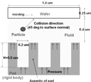
차원모델을구성하 였다(Fig. 1).
입자는100 nm
정도크기의silica (SiO
2),
alumina(Al
2O
3)
또는ceria(CeO
2)
로 구성하고,
형상은 실제사용되는연마입자의형상이거의구형이아님을 반영하기위하여 구형,
사각형,
임의의사다리꼴,
육각형등으로모델링하였다
.
웨이퍼표면은Cu, Al, W,
SiO
2, Si
3N
4등다양한금속및세라믹재료로구성하 였으며,
입자 및 표면재료는elastic-isotropic material
로구성하였다
.
또한,
임의의표면형상및거칠기를가 지는 패드와 이에 의한 유체유동의 영향을 고려하기 위하여 본 연구에서는micro-grooved surface
로 모델 링하였다.
해석을위한 경계조건으로서,
입자와wafer
표면
,
그에 맞닿은 슬러리 유체의 유한요소들을FSI
경계조건을부여하였다
.
해석은실제
CMP
공정에서와같이일정한압력하에서웨이퍼표면이일정속도로회전하고이에따라슬러 리유동이유발되는조건하에서입자가초기속도를가 지고웨이퍼표면에
45
o 각도로충돌하도록하여해석 을 수행하였다.
구형외에각진 모서리를갖는 입자의 경우,
표면과의 접촉부분의형상에따라 결과가크게달라질수있음을감안하여각경우비교를위해모서 리부로 접촉하여 큰 응력과변형이 발생하도록 하여 시뮬레이션을 수행하였다
.
초기속도는 연마입자를 이용한연마제트가공에서입자분출속도가수백
m/s
이상 임을 고려하여최저속도에서의표면파손의영향을파악하기 위하여
100 m/s
로선정하였다.
슬러리유체는Fig. 1
에서보이듯이외부압력하에서의매우좁은미세채널내에서의유동이며실제유체에서매우작지만밀
Fig. 1. Schematic of a 2-D finite element model used in
this study.
도변화가 존재함을 감안하여 극소압축성유동
(slightly compressible flow)
으로모델링하였다.
Table 1
및Table 2
에해석 조건및해석에사용된재료물성치를요약
,
제시하였다.
슬러리유체는일반적으로 많이사용되는
KOH
계fumed silica
기반염기성용액의물성을이용하였다
.
재료물성치는기존의연구결과및참고문헌으로부터수집되었다
[2,11].
3. 결과 및 고찰
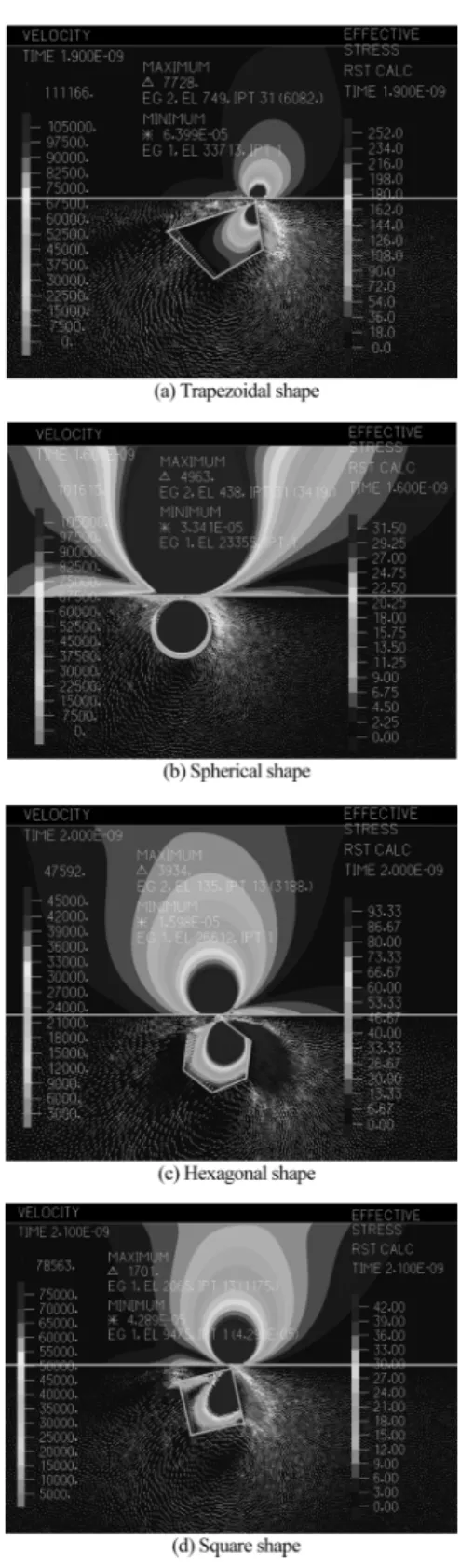
Fig. 2
는 다양한형상을 갖는CeO
2 연마입자와 알루미늄표면의충돌접촉에대해시뮬레이션한결과로 서 각각의 입자에 대해 웨이퍼표면과의 충돌로인해 가장큰응력이나타나고있는상태를보여주고있다
.
슬러리유동의 속도및분포는화살표로제시하였다
.
각입자형상에따른 시뮬레이션결과로부터얻어진
최대응력의크기를
Table 3
에요약하였다.
Fig. 2
및Table 3
으로부터 다른형상에 비해상대적으로더욱날카로운모서리로접촉하는사다리꼴형
Table1.FE simulation conditions and material properties of abrasive particle
Particle Shape:4 shapes (Trapezoid, Square, Sphere, Hexagon)
Diameter:50, 100, 200 nm Fluid Viscosity:0.0015 Pa·sec (at 20
oC)
Density:1.5 g/cm
3Simulation
Conditions
Pressure:0.04 MPa Temperature:20
oC Initial speed of particle:100 m/s
Wafer moving speed:1~5 m/s Table 2. Mechanical properties of the particle and wafer surface used in the simulation
Material Young’s
modulus (GPa) Poisson’s
ratio Density (g/cm
3)
Particle SiO
270 0.2 2.0
CeO
2181 0.311 7.65
Al
2O
3380 0.26 4.0
Wafer surface
Cu 135 0.33 8.95
Al 70 0.35 2.7
W 411 0.28 19.2
SiO
270 0.2 2.0
Si
3N
4200 0.23 2.4
Fig. 2. Snapshots of the simulation results obtained by
using various particle shapes under the contact
between ceria particle and Al surface.
상에서가장응력이크게나타나며다음으로구형입자 에서큰응력이발생하고있음을보여주고있다
.
이는삼각형
,
구형,
사각형입자를고려한기존의다른연구 결과에서도 보이듯이표면과접촉하는부분의입자형 상에따라 응력및재료제거량이크게 변화하기때문으로 판단할수 있다
[8].
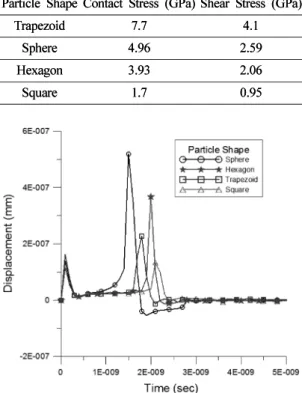
이에덧붙여, Fig. 3
의그래프는각형상의입자가표면에근접하기시작하여충 돌이후까지전체시뮬레이션동안 입자가표면에접
촉한 노드
(node)
에서의 시간에 따른변형을 보여준다.
그래프에서 시뮬레이션 초기에 공통적으로 나타나는 변형은입자와웨이퍼의운동개시로인해슬러리유체에 유동이발생하면서이로인한순간적인변형이며
, 2ns
부분에서접촉이일어나 대변형이발생하고있다
.
윤활 상태에서 입자와 표면이점접촉할 경우 높은 압력이 형성되어서유체의점도가매우크게상승하고표면에 서 상당한탄성변형이 발생하게된다.
제시된그래프 에서 보이듯이 구형 및육각형 입자의경우 사각 및사다리꼴형상의입자에서보다상대적으로큰변형이 발생됨을알수있는데
,
이는이입자들의표면에서의접촉형상으로인해슬러리유체의압착효과
(squeeze)
가 크게나타나기때문으로사료된다.
또한
, Table 3
의결과는모든경우에알루미늄의항복강도
(30~120 MPa)
를크게초과하는응력이발생하고표면에큰변형및결함이발생할것을보여주고있다
.
이러한결과는충돌접촉시입자가상당히큰에너 지를가지는경우에얻을수있는결과로서
,
충돌직전 의ceria
입자의속도는30~50 m/s
를 나타내었다.
초기 속도가수십m/s
로작을경우에는슬러리유체유동의 저항으로인하여표면에입자의충돌이이루어지지않 거나매우미약한응력이발생하여표면파손이나재료 제거가이루어지지 않음을알수 있었다. Abrasive jet machining
과같은micro-particle
에의한가공공정에서노즐을 통한
slurry
분사속도가 초당 수백m
에서 수km
에이르는것을감안하면이러한결론은타당한것으로판단된다
.
그러나,
본결과로부터슬러리가고속 분사되지않는CMP
공정에서는공정조건상유동에의 해입자가이와같이큰에너지를받아웨이퍼표면에 충격을가함으로써재료제거나표면에손상또는결함 이발생하는것은불가능할것으로예측되며,
따라서표면결함이나재료제거는웨이퍼
-
패드간접촉계면사이 에서연마입자의직접적인3
개체접촉(3-body contact)
에 의해서만 가능할 것으로 판단된다
.
그러나,
실제CMP
공정에서는정량적으로는아직밝혀져있지않으 나슬러리에의한화학작용의영향으로표면의항복 강도나탄성계수가 많이 저하되므로,
추후 이를고려 한추가적인고찰이요구된다.
또한
,
다양한웨이퍼및입자재료의영향은,
예비시뮬레이션결과웨이퍼재료에따라접촉응력의크기는 변화가크지않으나재료의탄성계수의크기와비례적 으로증가하는관계를보였으며입자재료의경우상대 적으로 낮은 밀도의 재질을갖는 입자는유동유체의 저항으로웨이퍼표면에의충돌자체가이루어지지않 거나현저히충돌속도가감소하여거의표면파손이일 어나지않았다
.
이에대해서는추후다른논문을통하여자세히기술하고자한다
.
4. 결 론
본연구에서는연마입자에의한가공시입자
-
표면간 충돌접촉에대해 다양한입자형상의영향을2
차원 유Table 3. Maximum normal and shear stresses on the wafer surface induced by the particle with various shapes
Particle Shape Contact Stress (GPa) Shear Stress (GPa)
Trapezoid 7.7 4.1
Sphere 4.96 2.59
Hexagon 3.93 2.06
Square 1.7 0.95
Fig. 3. Change in the displacement of the spot on the Al surface impacted by the particle during the simulation.
Table 3. Maximum normal and shear stresses on the wafer surface induced by the particle with various shapes
Particle Shape Contact Stress (GPa) Shear Stress (GPa)
Trapezoid 7.7 4.1
Sphere 4.96 2.59
Hexagon 3.93 2.06
Square 1.7 0.95
한요소모델을통하여해석하여다음과같은결론을얻 었다
.
1)
가공면에대하여다양한입자형상에의한충돌접 촉 시뮬레이션결과,
작은 충돌에너지에 의해서는 슬 러리 유체유동 저항의영향으로 인해 표면파손 또는 재료제거가불가능하였다.
2)
유한요소해석에슬러리유체및유동을고려하여기존의유한요소해석을이용한연구들에서와차별되 는새로운결과들이도출가능하며
,
실제공정에서의현 상을시뮬레이션할수있으므로향후다양한공정변수 의영향을고려한해석이이루어지면공정조건설정과 수율 향상에이론적 및실제적인 도움이될 수있을 것으로기대된다.
후 기
이논문은
2010
년도한남대학교학술연구조성비지원에의하여연구되었음