• 검색 결과가 없습니다.

The User Motion Pattern Control System for The Simulated Vehicle

N/A
N/A
Protected

Academic year: 2021

Share "The User Motion Pattern Control System for The Simulated Vehicle"

Copied!
5
0
0

로드 중.... (전체 텍스트 보기)

전체 글

(1)

The User Motion Pattern Control System for The Simulated Vehicle

Tae-Wan Kim ․ Dong Myung Lee

Dept. of Computer Engineering, Tongmyong University*

ABSTRACT

The purpose of this paper is to design and implement the user motion pattern control system for the simulated vehicle. After analyzing the user motion patterns in the system, the patterns are used to control the moving direction of the simulated vehicle such as forward, backward, turn right, turn left etc. The patterns in the system around are sent to the simulated vehicle in real time. In order to execute the suggested user motion pattern control system, the Kinect is used for executing the system. The Kinect recognizes the specified user motion patterns and it transmits the data to the user motion pattern control system. There are nine kinds of the user motion patterns in the system for controlling the simulated vehicle. In addition to this, some sensors are used to detect the condition of the simulated vehicle. GPS is also used to estimate the current location of the simulated vehicle and to obtain the driving information.

Keywords: Simulated Vehicle, User Motion Pattern, Kinect

I. Introduction 1)

Coming era of advanced information in earnest, the machines with built-in computer are already became the component of today society and it`s impact in our daily life is increased day by day. We still use keyboard, mouse, joystick and more as an interface for the computer mani- pulation. The technologies of more natural interface between the computer and the person is not widely adapted to various industries not yet.

A human motion is best natural tool as a language and a relationship of people for an interaction. The researches for implementing the best natural interface between the human motion and the computer are progressed now dy- namically. But researches in our country are still the slight stage when compared with other countries what have the developed science. The component technologies are greatly expected for economic and social industrial effects.[1-5]

To recognize human motions, we will use the Kinect module that is used for a side of recent gaming industry.

The Kinect recognizes the human actions and it can control

Received 4 October, 2011; Revised 12 June, 2012 Accepted 17 July, 2012

† Corresponding Author: [email protected]

a display inside a game. In other words, it can be used for realizing the controlling of the display of computer when applying only the human action, for example, a scene of the movie-minority report.[6]

So we consider how to control real object such as a vehicle, a helicopter and so on when the human action is used only. After that, the detailed manipulation of an object can be made possible. Upward a device, what is such as a probe or a unmanned and son on, is applied to the place where the human can look a display when he can not go directly. In this case, the manipulation will be possible by how being a little more convenient.

The purpose of this paper is to design and implement the user motion pattern control system for the simulated vehicle. After analyzing the user motion patterns in the system, the patterns are used to control the moving direction of the simulated vehicle such as forward, backward, turn right, turn left etc. The patterns in the system around are sent to the simulated vehicle in real time.

In order to execute the suggested user motion pattern control system, the Kinect is used for executing the system.

The Kinect recognizes the specified user motion patterns

and it transmits the data to the user motion pattern control

system. There are nine kinds of the user motion patterns

(2)

in the system for controlling the simulated vehicle. Some sensors are used to detect the condition of the simulated vehicle. GPS is also used to estimate the current location of the simulated vehicle and to obtain the driving infor- mation.

II. Design Considerations

In order to design the user motion pattern control system, three design considerations are analyzed and used to the suggested system as follows:

● The most important factor for the user motion pattern control system is to feel his mind easily and to control correctly for users, so the Kinect based control concept is adapted to the suggested system.

● The sufficient analysis of the user motion patterns should be sent to the server because the patterns are very large, they are executed to the server for fast processing.

● Because the correct awareness of the various status in the surrounding environments is very important, the sensors such as ultrasonic sensor, gyro sensor, accele- rated sensor, light sensor, temperature sensor, GPS and camera are necessary for executing the user motion patterns.

III. System Design and Implementation 1. System Overview

The system overview of the user motion pattern control system for the simulated vehicle is shown in Fig. 1. The

Fig. 1 Overview of User Motion Pattern Control System

system is consisted of two parts: the monitoring part and the simulated vehicle part. The user motion data from the Kinect is transmitted into the server in the monitoring part by the wireless communication module in the si- mulated vehicle part of the simulated vehicle. Then, the simulated vehicle part is remotely controlled by the user motion pattern control system in the monitoring part. Some status data of the surrounding environments are acquired and it is transmitted into the server in the monitoring part for monitoring the surrounding environment of the simulated vehicle.

2. System Configuration

The overall system configuration of the user motion pattern control system for the simulated vehicle is shown in Fig. 2.

A. Monitoring Part

The monitoring part is consisted of the kinect module, the processing module and the interface module. Those modules are executed in the server. The kinect module

Fig. 2 System Configuration

(3)

performs the pattern recognition and pattern analysis functions. If the pattern recognition function receives the motion patterns of image format from the users, it is transmitted the image to the kinect module by the serial communication protocol. If the pattern analysis function receives the image from the kinect module, it analyzes and extracts some characteristics of motion pattern. It is defined that the types of characteristics motion pattern are the motion for moving the simulated vehicle(forward, backward, turn right, turn left, etc.).

The processing module performs the data transmission and the data processing functions. The data transmission function is processed to transmit the characteristics of user motion patterns to the simulated vehicle part by wi- reless communication module. The data processing function is processed to acquire and analyze the status of some surrounding environment, and the data is returned to the interface module of the monitoring part.

The interface module is processed to provide the status of surrounding environment in the simulated vehicle part to the monitor of server. And then the user motion patterns display to the Kinect display device.

B. Simulated Vehicle Part

The simulated vehicle part is consisted of the control module and the transmission module. The control module performs the data analysis, the vehicle control function.

If the data analysis function in the simulated vehicle part receives the characteristics of motion pattern from the data transmission function in monitoring part, it analyzes among received data to distinguish data type for detecting the vehicle motor control motions.

If the vehicle control function receives the data from the data analysis function, it controls the motor in the simulated vehicle.

The transmission module performs the image data trans- mission and the sensor data transmission functions. This module is executed in wireless communication board installed to the simulated vehicle. If the image data transmission function receives the image from the vehicle control function in the control module, it sends the image to the data pro- cessing function in the monitoring part. Also the sensor

Fig. 3 Types of Sensor Configuration in Simulated Vehicle Part

data transmission function sends the sensing data to the data processing function in the monitoring part.

Fig. 3 shows the types of sensor configuration in the simulated vehicle part.

The sensing data is generated from sensors, and they are embedded in the simulated vehicle and are gathered by some operations: 1) Sensing of the current location of the simulated vehicle by GPS receiver; 2) Sensing of some obstacles neighboring the simulated vehicle by ultrasonic sensor; 3) Sensing of the inclination of the road by gyro sensor; 4) Sensing of the simulated vehicle speed by accelerometer sensor; 5) Sensing of the light quantity by light sensor; 6) Sensing of the temperature in the en- vironment of the simulated vehicle by temperature sensor.

3. Motion Pattern Definition

Fig. 4 and 5 shows the motion patterns defined as the start motion patten and the driving motion patten for controlling the simulated vehicle.

Fig. 4 in left side shows the 3D motion pattern for presenting the starting of the user motion pattern control system using two hands, and it can be easily shown in Fig. 4 in right side as 2D motion patterns located in 3×3 area.

Fig. 5 shows the driving motion patten for driving the

(4)

Fig. 4 Start Motion Pattern

Fig. 5 Driving Motion Pattern

simulated vehicle direction such as forward, backward, turn right, turn left etc. using the right hand.

The driving motion patterns located in the 3×3 area are operated only by right hand. There are nine driving motion patterns, six motion patterns of that mean the progressing directions that are presented by arrows. Two driving motion patterns that mean rotation is presented by yellow circles. One driving motion pattern means the stopping of the simulated vehicle and it is presented by purple circle.

IV. Experiments and Performance Analysis

Fig. 6 and 7 shows the experiments for performance

Fig. 6 Experiments of Start Motion Pattern

Fig. 7 Experiments for Driving Motion Pattern

estimation of the user motion patterns to control the si- mulated vehicle.

Fig. 6 shows the exact 3D coordinates of two hands about the start motion pattern defined in Fig. 4 for con- trolling the user motion pattern control system. Because the coordinate values (x,y,z) means that the 3D location of the start motion pattern, it can be changed into different values according to the location of the start motion pattern.

Fig. 7 shows the exact 3D coordinates of right hand about the driving motion pattern in case of the forward direction defined in Fig. 5 for driving the simulated vehicle.

The coordinate values (x,y,z) can be also changed into different values according to the location of the driving motion pattern.

V. Conclusions

In this paper, the user motion pattern control system

for the simulated vehicle is designed and developed. When

(5)

the user motion patterns, what is already defined, is selected, the control of the simulated vehicle can be operated quite freely by nine kinds of the user motion patterns. Those patterns have forward, left forward, right forward, left rotation, right rotation, backward, left backward, right backward and stop.

The user motion pattern control system for the simulated vehicle will be applied for wide areas. The suggested system can be applied efficiently for somewhat to dangerous industry, being in all the time and the place. Therefore the happened industrial accident can be reduced.

It can be developed in the basis of the user free motion if the proposed system is up built and adapted to robot system. The proposed system can be used to what taking a heavy load, a rescue structure site such as the collapse and the movement in the contaminated environment by controlling human motions.

이 논문은 2012년도 Brain Busan21사업에 의하여 지원 되었음.

References

1. Sungkyunkwan Univ., “Investigated Core Technologies Based on Computer Vision That are Needed To Realize a User-friendly Computer Interface,” NIPA Report, IITA- 0549 : 1-35, 2001. 7.

2. K. K. Kim, H. J. Kim, S.H. Cho and J. Y. Lee “Gesture Recognition for Natural Human-Robot Interaction,” ETRI Brochure & Report, 20 (2): 11-20, 2005. 4.

3. Chang-Soon Bok, Yeon-Mee Son, Yung-Chul Bang and Bo-Kyun Na, “Vision-based Hand Gesture Recognition for Computer Control,” Korea Information Science Society, 35 (2B): 192-195, 2008. 10.

4. Seon-Ok Yang, Hyung-Ill Choi, “User’s Skin-color Extraction For Environmental Adaptive Gesture Recognition,” Korea Information Science Society, 22 (2A): 665-668, 1995. 10.

5. Jae Yong Oh, Ki Tae Bae, Man Jin Kim, Chil Woo Lee,

“Gesture Interface for Controlling Intelligent Humanoid Robot”, Journal of Korea Multimedia Society, 8 (10): 1337 -1326, 2005. 10.

6. Tae-Wan Kim, Kyung-su Seo, Kwang-Soo Park, Dong Myung Lee, “Development of User Motion Pattern-Based Simulated Vehicle Control System,” Proceedings of Asian Conference on Engineering Education 2011(ACEE 2011), The University of Tokushima, pp.PS-22:1~PS-22:4, 8~9 (8) October 2011.

김태완 (Tae-Wan Kim)

Feb. 2012.: Dept. of Computer Engineering in Tongmyong University (B.S)

Mar. 2012.~Present: Studying M.S Degree in Dept. of Computer Media Engineering, Tongmyong University (M.S) Research Fields: Embedded System, Image Processing System, Data Processing System

Phone: +10-2787-6419 E-mail: [email protected]

이동명 (Dong Myung Lee)

Feb. 1982.: Dept. of Computer Science in Soongsil University (B.S)

Aug. 1990.: Dept. of Computer Science in Soongsil University (M.S)

Aug. 1997.: Dept. of Computer Science in Soongsil University (Ph.D)

Mar. 1982.~Feb. 2000.: Principle Researcher in Electronics and Telecommunications Research Institute (ETRI)

Mar. 2000.~Present: Professor in Dept. of Computer Engineering in Tongmyong University

Research Fields: Capstone Design in Engineering Education Accreditation, Wireless Communication System, Sensor Network, Intelligent Robots

Phone: +051-629-1176

Fax: +051-629-1169

E-mail: [email protected]

수치

Fig.  1  Overview  of  User  Motion  Pattern  Control  System
Fig.  3  Types  of  Sensor  Configuration  in  Simulated  Vehicle  Part

참조

관련 문서

For this purpose, the issues such as the energy consumption pattern, the justification for integrating air pollution control and energy pricing functions,

Five days later, on 15 January 1975, the Portuguese government signed an agreement with the MPLA, FNLA and UNITA providing for Angola to receive its independence on 11

Usefulness of co-treatment with immunomodulators in patients with inflammatory bowel disease treated with scheduled infliximab maintenance therapy.. Oussalah A, Chevaux JB, Fay

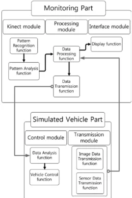
The whole system combines the master-slave remote control robotic system (the motion simulator and joystick/haptic interface device), the virtual reality system

Inclusion and Inclusiveness: Shared Vision of Youth for Local, National, and Global Village Inclusion at large stands for embracing populations with disabilities and

웹 표준을 지원하는 플랫폼에서 큰 수정없이 실행 가능함 패키징을 통해 다양한 기기를 위한 앱을 작성할 수 있음 네이티브 앱과

It is impossible to change the voltage across a capacitor by a finite amount in zero time, for this requires an infinite current through the capacitor.. (A capacitor resists

The index is calculated with the latest 5-year auction data of 400 selected Classic, Modern, and Contemporary Chinese painting artists from major auction houses..