◎ 논 문 ISSN (Print): 1226-9883
Performance Measurement of a Tubular Type Turbine System for Small Hydropower by Field Test
Yeong-Ho Hwang * , Young-Ho Lee ** , Young-Do Choi ***
현장시험에 의한 소수력발전용 튜블러수차시스템 성능계측
황영호 *
*ㆍ이영호**
**ㆍ최영도***
***Key Words : Small hydropower(
소수력발전), Tubular type turbine(
튜블러수차), Performance measurement(
성능계측), Field test(
현장시험) ABSTRACT
Recently, small hydropower attracts attention because of its renewable, clean and abundant energy resources to develop.
Therefore, a tubular type hydro turbine is proposed for small hydropower in this study because the turbine has relatively simple structure and high possibility of applying to small hydropower. The purpose of this study is to investigate the performance characteristics of the turbine by field test. Field test iss conducted using one tubular turbine system as well as serial arrangement system by two tubular turbines taking into consideration of actual operation conditions. The results show that efficiency of test turbine changes considerably by the runner vane angle. Best efficiency of one turbine arrangement is higher than that of two turbine serial arrangement.
†
†
1. Introduction
Recently, small hydropower attracts attention because of its renewable, clean and abundant energy resources to develop. However, suitable turbine type is not determined yet in the range of small hydropower and it is necessary to study for the effective turbine type
(1-9)
. Moreover, relatively high manufacturing cost by the complex structure of the turbine is the highest barrier for developing the small hydropower turbine. Therefore, a tubular turbine is adopted because the turbine has relatively simple structure and high possibility of applying to small hydropower.This study mainly deals with the performance characteristics of the tubular turbine by field test.
Even though the field test has some restrictions against the experimental range of head and flow rate in
* Shinhan Precision Co. Ltd.
** Korea Maritime University
*** Mokpo National University(Corresponding Author)
† 교신저자, E-mail : [email protected]
comparison with those of laboratory test, actual performance of the test turbine can be confirmed in detail under the test conditions at the test field.
2. Test Tubular Turbine and Experimental Setup
Figure 1 shows the inlet and outlet of a tubular turbine for field test. Flow rate, head, and rotational speed at the designed point are determined to
Q
=0.3m3
/s,H
=12m, andN
=1800min-1
. The number of runner blade isZ
=5 and the outer diameter of runner vane isd
=280mm.The runner vane angle is changed from
θ
=10 to 26 degrees in order to examine the influence of the runner blade angle. Guide vanes are installed in front of the runner blade in the flow passage and the guide vane angle is fixed at an optimum angle. All the materials of runner vane, guide vane, shaft and casing are made of stainless steel.Figure 2 shows the experimental setup of the test
(a)
(b)
Fig. 3 Measuring points of one tubular turbine arrangement for field test : (a) actual arrangement and (b) schematic view of test facility (a)
(b)
Fig. 1 (a) Turbine inlet and (b) turbine outlet of test tubular hydro turbine for field test
Fig. 2 Schematic view of experimental setup of test turbine system at test field
turbine arrangement.
All the measurements for the test turbine system are conducted with reference to the standards of JEC-4001
(10)
and JEC-4002(11)
.Pressure measurement points of P11, P12, and P13 are located at the regions of test turbine inlet, turbine casing at the runner vane and the turbine draft tube outlet. In order to acquire performance data from the test turbine, unit output power (
P u
=P
/H 3/2
,P
: output power), unit flow rate (Q u
=Q
/H 1/2
), and unit rotational speed (N u
=N
/H 1/2
) by the variation of electrical load, flow rate and runner vane angle are measured.Fig. 4 Serial arrangement of two tubular turbines for field test
Fig. 5 Performance curves by the condition of runaway speed
Fig. 6 performance curves by the variation of runner vane angle
Moreover, serial arrangement system by two tubular turbines is also tested as shown in Fig. 4 in view of higher head condition in comparison with that of the designed head of test turbine.
3. Results and Discussion
3.1. Performance curves by runaway speed condition
Figure 5 shows the performance curves by the condition of runaway speed. Test turbine is designed to be operated up to the maximum rotational speed of 2.3 times the rated rotational speed. Under the operating condition of runaway speed at the test field, rotational speed increases up to the 1.9 times the rated rotational speed.
The result of decreasing tendency of the rotational speed by the increased runner vane angle is reasonable because, as the runner vane angle increases, flow passage area between the runner vane increases. And thus, flow rate increase in proportion to the runner vane angle but rotational speed decrease in reverse proportion to the runner vane angle.
3.2. Performance curves by the variation of runner vane angle
Figure 6 hows the pressure distribution by the variation of runner vane angle. Electrical load is fixed to 30kW, which almost corresponds to the maximum value of one test turbine output power. As the vane angle
θ
increases, unit rotational speedN u
decreases gradually. Moreover, local pressure is measured at the measuring points of test turbine inlet (P11), turbine casing at the runner vane (P12), and the turbine draft tube outlet (P13).Measured pressures at each point reveal that as the runner vane angle increases, pressures increases at P11 and P12 accordingly but P13 shows almost constant values regardless of the runner vane angle variation.
Measured pressure at the turbine casing at the measuring point of test turbine inlet (P11) shows relatively higher value than that of the pressure at the runner vane (P12). However, pressure at the turbine draft tube outlet (P13) shows almost does not change regardless of runner vane angle variation.
Pressure difference between the measuring points
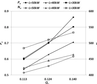
Fig. 7 Performance curves by the variation of flow rate Fig. 8 Performance curves by the variation of electrical load
shows that difference value between P12 and P13 is considerable in comparison with the value between P11 and P12. This result implies that almost pressure at P12 is converted to output torque when flow passes to the passage between the points of P12 and P13.
3.3. Performance characteristics curve by flow rate variation
Figure 7 shows the performance curves by the variation of flow rate when runner vane angle is fixed.
It is remarkable that as flow rate increases, unit output power
P u
and unit rotational speedN u
increase accordingly.The increased value of rotational speed is almost proportional to the electrical load when flow rate is fixed to a value. However, in actual case, each rotational speed by the variation of electrical load may become same value because the influence of the electrical load is disappeared when the turbine system is connected to an electric power grid, which means that, in actual grid system, electrical load is constant.
In case of output power, the increasing tendency of output power value at each electrical load is not proportional to the value of flow rate, especially at the high electrical load range over 50kW in this study.
Moreover, output power by electrical load
L
=30kW is higher than that ofL
=40kW.This result implies that output power is not dependent on the electrical load when flow rate changes because
best efficiency locates only at the region of designed operation condition of the test turbine. If the electrical load changes, the operating condition and performance of the turbine changes as well. However, as mentioned above, electrical load is constant in actual grid system.
3.4. Performance curve by the variation of electrical load
Figure 8 shows the performance curves by the variation of electrical load. When the output power is used for a restricted local area without connection to electrical power grid, turbine performance will be varied from the designed condition by load. Therefore, dependence of the turbine performance on the load is examined in this study.
According to the experimental results from the field test, as the load
L
increases, unit output powerP u
reveals lowest value at the load of
L
=40kW in all cases of runner vane angle but almost similar value at the loadL
=30kW and 50kW. Unit flow rateQ u
decreases by gentle slopes in all cases of runner vane angle when the load increases. However, unit rotational speedN u
decreases remarkably when the load increases.
Test result suggests that rotational speed is almost in inverse proportion to the variations of runner vane angle and electrical load. However, output power is not proportional to the electrical load, even though the output power is proportional to the variation of runner vane angle.
Fig. 9 Performance curves by serial arrangement of two tubular turbines
Fig. 10 Comparison of efficiencies by one turbine arrangement and two turbine serial arrangement
3.5. Performance by serial arrangement of two tubular turbines
Figure 9 indicates performance curves by serial arrangement of two tubular turbines. Subscript letters A and B in the figure mean the front and rear turbines.
As the runner vane angle
θ
increases, flow rate increases gradually. Especially, output power of rear turbine B shows higher value compared with that of front turbine A at almost range of runner vane angle. It is conjectured that this result is originated from the higher pressure in the front turbine A than the designed pressure and thus, the output power of front turbine A is lower in comparison with that of turbine B.3.6. Comparison of efficiencies by one turbine with two turbines serial arrangement
Figure 10 compares efficiencies by the cases of one turbine arrangement and two turbines serial arrangement.Best efficiency locates at the runner vane angle
θ
=16 degrees in case of one turbine arrangement.When the runner vane angle is below
θ
=12 degrees, serial arrangement of two turbines have higher efficiency than that of one turbine arrangement. However, when the runner vane angle is overθ
=14 degrees, one turbine arrangement shows higher efficiency than that of serial arrangement of two turbines.4. Conclusions
From the field test for a tubular turbine system, performance characteristics are examined. Under the operating condition of runaway speed at the test field, rotational speed increases up to the 1.9 times the rated rotational speed. Efficiency of test turbine changes considerably by the runner vane angle. As flow rate increases, unit output power
P u
and unit rotational speedN u
increase accordingly. Rotational speed is almost in inverse proportion to the variations of runner vane angle and electrical load.Moreover, according to the comparison of turbine system performances between one tubular turbine system and two turbine serial arrangement system, best efficiency of one turbine arrangement is higher than that of two turbine serial arrangement. However, lower efficiency is found in case of one turbine arrangement than that in case of two turbines serial arrangement when runner vane angle is below