Ⅰ. Introduction
In these days, surface permanent magnet synchronous motors (SPMSMs) are widely used due to its various advantages such as high efficiency, high power density, and fast dynamic control capability. To drive the SPMSMs, the current vector control scheme has been generally employed in industries because it shows a good dynamic control performance. However, the current vector controller requires high precision phase- current sensing units and a micro-controller supporting a fast calculation. Therefore, the implementation cost of the current vector controlled SPMSM drives is becoming an obstacle in low-cost applications.
For SPMSM drives used in low-cost applications, a current sensor-less vector control scheme was proposed in [1], wherein phase currents of SPMSM are estimated using a voltage equation. Although phase-current sensing units are not used in [1], a current estimator and a current vector control function should be executed at every pulse-width modulation (PWM) period in motor control software and thus a microprocessor with a fast computation speed is needed for its implementation. The single-shunt based phase- current sensing strategy can be considered for low-cost applications [2, 3]. However, it also requires a high-performance micro-controller for its implementation because voltage vectors should be modulated at every half PWM switching
Voltage Angle Control of Surface Permanent Magnet Synchronous Motor for Low-Cost Applications
Kwang-Woon Lee
*★, Guechol Kim
*Abstract
This paper presents a voltage angle control strategy for surface permanent magnet synchronous motor (SPMSM) drives used in low-cost applications, wherein a current vector control is not employed. In the proposed method, the current vector control scheme, which requires high precision phase-current sensing units and a fast calculation capability of a motor drive controller, is replaced with the voltage angle controller. The proposed voltage angle controller calculates a d-axis voltage command to make the d-axis current zero by using a simple equation obtained from the voltage equation of SPMSM. The proposed method shows performance similar to the current vector controlled SPMSM drive during steady-states and its structure is very simple and thus it can be easily implemented with a low-cost microcontroller. The effectiveness of the proposed method is verified through simulations and experiments.
Key words: SPMSM, Current Vector Control, Voltage Angle Control, Inverter, PLL
* Dept. of Electronic Engineering, Mokpo National Maritime University
★ Corresponding author
E-mail:[email protected], Tel:+82-61-240-7269
※ Acknowledgment
This work was financially supported in part by VCTech. Co., Ltd.
Manuscript received Sep. 7, 2018; revised Sep. 11, 2018; accepted Sep. 12. 2018
This is an Open-Access article distributed under the terms of the Creative Commons Attribution Non-Commercial License (http://creativecommons.org/licenses/by-nc/3.0) which permits unrestricted non-commercial use, distribution, and reproduction in any medium, provided the original work is properly cited.
195
period for the single-shunt based current sensing.
In addition, it should be noted that much effort is required in designing a printed circuit board (PCB) pattern for the single-shunt based current sensing because its performance is very sensitive to inverter noises.
In the low-cost applications such as fan motor and actuators used in a small-capacity personal transport, good dynamic control performance is relatively less important and the current vector control does not have to be used. It means that a voltage angle control strategy without the current vector control function can be considered for low-cost SPMSM drives. A conventional approach using the voltage angle control has been implemented based on a look-up table wherein the voltage angles at various operating points are saved [4]. The key point demanded in the look-up table based voltage angle control method is that the voltage angle should be deliberately chosen so as to the d-axis current should remain zero. Otherwise, excessive d-axis currents can be supplied to SPMSM and result in an efficiency decrease of SPMSM drive. It should be noted that making a voltage angle look-up table that shows satisfactory results over the entire operating ranges of SPMSM is not easy and it requires a time-consuming effort.
To cope with this problem, this paper presents a simple voltage angle control strategy wherein a d-axis voltage command to make the d-axis current zero is obtained by using an equation derived from the voltage equation of SPMSM.
The main advantage of the proposed method is that it shows performance similar to the current vector controlled SPMSM drive during steady- states if electrical parameters’ variation of SPMSM is negligible. In addition, the structure of the proposed voltage angle controller is very simple and thus it can be easily implemented with a low-cost microcontroller.
To prove the effectiveness of the proposed voltage angle controller for SPMSM drives,
simulations and experiments have been performed using SPMSM. The simulation and experimental results show that the d-axis current of SPMSM is controlled near zero during steady-states by the proposed voltage angle control method.
Ⅱ. Proposed Voltage Angle Control Strategy
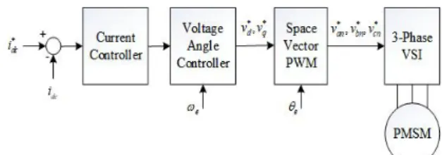
Figure 1 shows a conventional structure of the current vector controlled PMSM drive. As described in introduction, the current vector control scheme requires phase-current sensing units and a high-performance microcontroller for its implementation and thus it becomes less competitive in terms of cost. The voltage angle controlled PMSM drive does not use phase- current sensing units as shown in Fig. 2 and the d-q axes currents are not directly controlled.
Instead, the d-axis current is controlled to zero through the voltage angle control strategy and the q-axis current is regulated by the q-axis voltage command, produced by a speed controller in the case of Fig. 2.
Fig. 1. The structure of the current vector controlled PMSM drive.
Fig. 2. The structure of the voltage angle controlled
PMSM drive in speed control mode.
The voltage equations of SPMSM are given as follows:
d
d s d s e s q
v r i L di L i
dt w
= + - (1)
q
q s q s e s d e PM
v r i L di L i
dt w w l
= + + + (2)
where v
dand v
qare the d-q axis stator voltages, i
dand i
qare the d-q axis stator currents, r
sis the
stator resistance, L
sis the stator inductance, w
eis
the electrical angular velocity of the rotor, and l
PMis the permanent magnet flux linkage, respectively.
From (1) and (2), following equation can be derived.
(
2 2 2)
22
s d e s q
s e s d e s PM
d q
s s e s
r v L v
r L i L
di di
r L L
dt dt
w
w w l
w +
= + +
+ +
(3)
Ignoring derivative terms in (3) yields that
(
2 2 2)
2s d e s q s e s d e s PM
r v + w L v = r + w L i + w l L (4) From (4), the d-axis voltage command to make the d-axis current zero can be derived as follows:
(
2 *)
* e s PM e s q
d
s
L L v
v r
w l - w
= (5)
where v
*dand v
*qare the d-q axis stator voltage commands, respectively. To limit the q-axis voltage command under output voltage saturation condition, the q-axis voltage command has to satisfy the following condition.
2
( )
* * 2
3
q dc d
v £ æ ç v ö ÷ - v
è ø (6)
It should be noted that parameter uncertainties and voltage errors due to the dead-time of voltage source inverter (VSI) are not considered in (5). It means that the d-axis current cannot be exactly regulated to zero under parameter uncertainty conditions. However, considering the conventional look-up table based method, the d-axis voltage regulation method expressed in (5) can show appropriate performance in low- cost SPMSM drives wherein a high-performance control does not significantly affect the overall efficiency of the system.
When an input current to SPMSM drive has to be controlled, the input current can be measured at a relatively low-cost through a low-pass filtering of the inverter dc-link current. In this case, although an instantaneous input current control is impossible, the proposed voltage angle control method can be applied as shown in Fig. 3 to control the d-axis current to be zero and a similar effect as the minimum copper loss control can be obtained at steady-states.
Ⅲ. Simulation and Experimental Results
3.1 Simulation Study
To see the effect of the proposed voltage angle control strategy, a simulation study using the machine parameters listed in Table I was performed.
For the simulation, the control structure of SPMSM drive was configured as the same as Fig. 3. It means that the dc-link current command is given and the average dc-link current is obtained through the low-pass filtering
Variable Name Value[unit]
Stator resistance 0.01945 [Ω]
Stator inductance 0.00008 [H]
PM flux linkage 0.0168 [Wb]
Number of poles 10
DC-link voltage 68 [V]
Table 1. SPMSM parameters.
of the dc-link current. The current controller in Fig. 3 is implemented using a conventional proportional-integral (PI) type controller and it outputs the q-axis voltage command necessary to track the dc-link current command. The voltage angle controller in Fig. 3 calculates the d-axis voltage command using the equation (5) and the maximum value of the q-axis voltage command is limited as the equation (6). The pole voltage of the inverter is obtained from the d-q
axis voltage commands using a conventional space vector pulse-width modulation (SVPWM) strategy. For the simulation, the PWM frequency of VSI was set to 12 kHz and a mechanical load proportional to the rotor speed of SPMSM was employed.
Figure 4 shows simulation results when the dc-link current command was set to 20[A]. It is seen from Fig. 4 that the d-axis current command is controlled to be zero at steady- states. However, when the magnitude of the d-q axis voltage command is very small such as a starting condition in Fig. 4, it is observed that the d-axis current deviates from zero; this is due to the dead-time effect in VSI. Therefore, it can be stated that the practical limit of the proposed voltage angle control method is observed from Fig. 3. The structure of the voltage angle controlled
PMSM drive in the dc-link current control mode.
0 1000 2000 3000
Wm_rpm
0 -20 -40 20 40
Ia
0 -10 -20 10 20 30
Id Iq
0 10 20
Vd_cmd Vq_cmd
0 0.2 0.4 0.6 0.8 1
Time (s) 0
400 800 1200
Tem_PMSM31*Wm_samp Mechanical speed [r/min]
a-phase current [A]
d-q axis current [A]
d-q axis voltage command [V]
Mechanical output [W]
d-axis current q-axis current
d-axis voltage q-axis voltage
Fig. 4. Simulation results when the dc-link current command was set to 20[A].
0K 2K 4K
Wm_rpm
0
-40 40
Ia
0 20 40
Id Iq
0 -10 10 20 30 40
Vd_cmd Vq_cmd
0 0.2 0.4 0.6 0.8 1
T ime (s) 0
1000 2000 3000
Tem_PMSM31*Wm_samp Mechanical speed [r/min]
a-phase current [A]
d-q axis current [A]
d-q axis voltage command [V]
Mechanical output [W]
d-axis current q-axis current
d-axis voltage q-axis voltage
Fig. 5. Simulation results when the dc-link current
command was set to 50[A].
Fig. 4. However, because the conventional look-up table based method can also suffer from the same problem, the practical application of the proposed method does not matter.
Figure 5 shows simulation results when the dc-link current command was set to 50[A].
Unlike Fig. 4, it is observed from Fig. 5 that the transient response of the d-axis current was improved. This is because the voltage error due to the dead-time is reduced at higher d-q axis voltage commands. From Figs. 4 and 5, it is clear that the proposed voltage angle control method can regulate the d-axis current to be zero at steady-states.
Figure 6 shows simulation results considering parameter uncertainties, wherein it is assumed
that the stator inductance and the PM flux linkage decrease 5 [%] from the nominal values listed in Table I. It is clearly seen from Fig. 6 that the d-axis current is not controlled to be zero due to the parameter errors. It means that the proposed method is sensitive to the parameter variations and further study is necessary to solve this problem.
3.2 Experimental Verification
To prove the proper operation of the proposed method, an experimental setup was configured as shown in Fig. 7. For the implementation of the proposed method, a low-cost microprocessor, AC33M4064 manufactured by ABOV semiconductor, was used [5]. The parameters of PMSM shown in Fig. 7 are the same as those of listed in Table I. The PWM frequency of the inverter system shown in Fig. 7 was set to 12 [kHz] and control functions for generating PWM gating signals were implemented at every 6 [kHz]. The whole control structure of the experimental setup is the same as Fig. 3. Because AC33M4064 does not support floating-point math operations in hardware, the control functions were implemented only using fixed-point math operations.
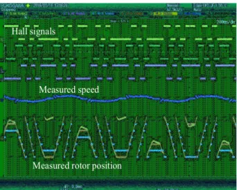
Three hall sensors were used for sensing of PMSM’s rotor position. Three external interrupt functions and one internal timer of AC33M4064 were used for the processing of three hall signals.
When the inverter operates, the output of hall signals can be affected by the switching noises of the inverter. For stable operation of hall signal based PMSM drive, the filtering of hall signals is
0K 2K 4K
Wm_rpm
0
-40 40
Ia
0 -20 20 40 60
Id Iq
0 -10 10 20 30 40
Vd_cmd Vq_cmd
0 0.2 0.4 0.6 0.8 1
Time (s) 0
1000 2000 3000
Tem_PMSM31*Wm_samp Mechanical speed [r/min]
a-phase current [A]
d-q axis current [A]
d-q axis voltage command [V]
Mechanical output [W]
d-axis current q-axis current
d-axis voltage q-axis voltage
Fig. 6. Simulation results considering electrical machine parameter errors when the dc-link current command was set to 50[A].
Inverter System
PMSM Load
Machine
Fig. 7. Experimental setup.
necessary. For this purpose, an additional phase- ocked-loop (PLL) function was programmed for the purpose of filtering hall signals and speed measurement [6]. Figure 8 shows experimental results related with hall signal processing. In Fig. 8, the waveforms of the measured speed and rotor position were obtained using the digital-to- nalog converter interfaced with AC33M4064. It is seen from Fig. 8 that the hall signal processing routine works properly.
The inverter system used in experiments does not support phase current sensing and thus the d-q axis currents cannot be monitored from the inverter system. Instead of monitoring the d-q axis currents, we observed the measured rotor position and the measured a-phase current to see how many d-axis currents are supplied to PMSM. It should be noted that a-phase current’s zero-crossing point (ZCP) exactly overlap with the ZCP of the measured rotor position when the d-axis current is controlled to be zero. Figure 9 shows the experimental results, obtained at steady- tates, when the proposed voltage angle control method was applied. It is seen from Fig. 9 that the ZCP of a-phase current nearly overlaps with the ZCP of the measured rotor position. Therefore, it can be stated from Fig. 9 that the proposed method properly works at actual condition.
a-phase voltage command
a-phase current Rotor position
ZCPs of voltage, current, and rotor position
Rms (C1) 14.35 [A] Freq (C1) 172 [Hz]
![Fig. 4. Simulation results when the dc-link current command was set to 20[A].](https://thumb-ap.123doks.com/thumbv2/123dokinfo/4670108.500090/4.892.476.771.585.1137/fig-simulation-results-dc-link-current-command-set.webp)
![Figure 5 shows simulation results when the dc-link current command was set to 50[A].](https://thumb-ap.123doks.com/thumbv2/123dokinfo/4670108.500090/5.892.111.410.156.713/figure-shows-simulation-results-link-current-command-set.webp)