Superconductivity and Cryogenics Vol.14, No.2, (2012), pp.12~15
```
Abstract-- This paper presents simulation and small-scale experimental tests of a fault current controller. Smart fault controller as proposed and proven conceptually in our previous work is promising technology for the smart power grid where distributed and even stochastic generation sources are prevalent and grid operations are more dynamic. Existing protection schemes simply limiting the fault current to the pre-determined set values may not show best performance and even lead to coordination failures, potentially leading to catastrophic failure. Thus, this paper designs fault current controller with a full bridge thyristor rectifier, embedding a superconducting coil for which the controller is electrically invisible during normal operation because the loss due to the coil is near-zero. When a fault occurs and the resulting current through the superconducting coil exceeds a certain value set intelligently based on the current operating condition of the grid, the magnitude of the fault current is controlled to this desired value by adjusting the firing angles of thyristors such that the overall system integrity is successfully maintained. Detailed time-domain simulations are performed and lab-scale testing circuits are built to demonstrate the desired functionality and efficacy of the proposed fault current controller
1. INTRODUCTION
T O overcome many problems of the current electric power grid, Smart Grid is envisioned, and enabling components of the Smart Grid are being actively investigated. The Smart Grid, understood as the overlaying of a unified communications and control system on the existing power delivery infrastructure, has significant positive impact on enhancing the energy efficiency and the customer service in a variety of ways. Its advanced two-way communications infrastructure allows the information transfer or exchange necessary to monitor operating status of the components, faults and power quality. Utilities can also locate problematic areas, inform customers, and restore service more quickly. Increasing distributed generation (DG) is also one of the noteworthy characteristics of the Smart Grid. This paper is in particular focused on DG’s stochastic contribution to the fault current levels, which may possibly break the existing protection coordination for fault current and result in catastrophic grid
* Corresponding author: [email protected]
failure. Note that existing protection devices operate with predetermined operating scenarios and may fail for the operating scenarios and the operating conditions not considered in the planning stage. Unpredictable nature of the emerging renewable energy and controllable loads may increase the complexity of the adequate protections. Fault current limiter must be an attractive solution to the increasing fault current levels. However, excessive limitation using fault current limiter (FCL), deterministic in nature, can delay the operation of the circuit breaker connected in series and harm the protection coordination.
The Smart Grid requires more adaptive and intelligent protection scheme.
Motivated by the aforementioned situation, smart fault current controller (FCC) was proposed and its functional efficacy was conceptually proven in our earlier work.
Unlike the FCL, FCC, employing a full bridge thyristor rectifier, maintains the fault current level at proper value by changing the firing angle of the thyristors [1]. By taking advantage of the advancing IT technology, system operators should be able to monitor the grid status accurately and make informed-decisions promptly for ensuring the system security. The control center should be informed on the adequate fault current levels at the critical locations where FCCs are deployed, and update the proper firing angle online. When a fault occurs, firing angle gate signals are applied to the relevant FCC and the fault current is regulated to the target current value and maintains the system integrity.
In this paper, a small scale FCC system is designed using a full bridge thyristor rectifier including a superconducting coil, and a thyristor control circuit. We perform short circuit tests simulating fault conditions, and verify its functional feasibility. The test results are compared with the simulation results and by doing these comparison, we verify feasibility of the FCC. It should be noticed that the goal of this paper is to perform small scale short circuit test and verify correct operation of the FCC circuit. Control and operations strategies are beyond the scope of this paper.
2. OPERATING PRINCIPLE AND STRUCTURE OF FCC
FCC consists of a full bridge thyristor rectifier embedding a superconducting coil, a thyristor control
Performance evaluation on Fault Current Controller System for the Applications of Smart Grid
Jae Young Jang
1, Woo Seung Lee
1, Jiho Lee
1, Young Jin Hwang
1, Hyun Chul Jo
1, Min Cheol Ahn
2, Kyeon Hur
1, Tae Kuk Ko
1,*1
School of Electrical and Electronic Engineering, Yonsei University, Korea
2
Department of Electrical Engineering, Kunsan National University, Gunsan
Received 14 March 2012; accepted 8 May 2012
Jae Young Jang, Woo Seung Lee, Jiho Lee, Young Jin Hwang, Hyun Chul Jo, Min Cheol Ahn, Kyeon Hur, and Tae Kuk Ko
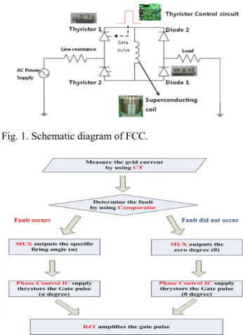
circuit which outputs the gate pulse signals when a fault occurs. Fig.1 presents the schematic of FCC system.
Before fault occurs, applied firing angle is zero and superconducting coil current is rectified through two thyristors, two diodes and large inductor fabricated by a superconducting coil. Therefore, AC loss at the superconducting coil is nearly zero [2]. After fault occurs at the grid, load is separated from the grid and fault current increases. The current transformer (CT) sensor installed at the superconducting coil detects the fault current and the phase angle control IC outputs the specific firing angle gate pulses to thyristor 1 and thyristor 2 alternatively. That is, phase angle control IC outputs the gate pulse to thyristor 1 at ω t = π + α and thyristor 2 at ω t = π + α . Therefore, thyristor 1 is turned on at ω t = π + α and thyristor 2 is turned on at ω t = π + α . The differential equation which represents fault state is as follows.
(1) for
) (
sin ω α < ω < π + α
=
+ Ri V t t
d
L di
L mt L
The complete response of this equation is,
(2) for
Ke ) - t
sin( ω θ +
-RLα < ω < π + α
= t
Z
i
LV
m t) (
0
sin( )
ωα
θ
α
LRL m
e
Z I V
K
− −
=
= +
=
−R L L
R
Z
2( ω )
2, θ tan
1ω
where, i
Lis the fault current, α is the thyristor firing angle, V
mis the magnitude of the input AC voltage, R is the resistance and L is the inductance of the superconducting coil [3]. From the equation (1) and (2), we verify the relationship between the firing angle and fault current. That is, fault current is adjusted by controlling the firing angle of the thyristors. Then, we can set up the proper firing angle which maintains the fault current at target value.
To prevent drastic increase of the fault current at first half cycle, large inductor is required in the FCC system.
However, large inductor fabricated by the normal conductor leads to the huge joule heating and voltage drop.
To solve this problem, superconducting coil is required because it can prevent the sudden increase of the fault current without joule heating loss. In this research, the high temperature superconducting (HTS) coil is employed to function as a large inductor.
3. EXPERIMENTAL SETUP
In this research, we perform the FCC short circuit tests.
To operate the FCC correctly, thyristor control circuit and superconducting coils are required. Experimental setups of these two components are introduced below.
3.1. The thyristor control circuit
To apply the gate pulse signal to thyristor with respect to the specific firing angle automatically, thyristor control circuit is needed. Fig. 2 shows the flow chart of the control circuit algorithm and Fig. 3 presents the whole control circuit diagram. Table 1 summarizes the model numbers of all devices used for designing the control circuit.
Fig. 1. Schematic diagram of FCC.
Fig. 2. Flow chart of the FCC control circuit.
Fig. 3. Schematic for FCC control circuit.
TABLE I
M
ODEL NUMBERS OF THE FCC CONTROL CIRCUIT DEVICES.
Device Model number
Comparator LM 311
D Flip-Flop 74LS74
Multiflexer ADG 409
Phase Control IC TCA 785
Bipolar Junction Transistor 2N3904
Thyristor
Diode SKKT 250/16E
SKKD 212/16
Thyristor control circuit is composed of phase control IC,
CT, comparator, D flip-flop, multiflexer (MUX) and
Bipolar junction transistor (BJT). Thyristor control
algorithm is as follows. By using the CT, current at grid is
measured as voltage signal and this signal is compared with
13
Performance evaluation on Fault Current Controller System for the Applications of Smart Grid
reference signal which means reference fault current. If CT output is larger than reference signal, comparator outputs 5V and this means that fault occurs. Comparator output is connected with D flip-flop. Due to the D- flip-flop, fault state can be maintained. MUX has two source inputs and control inputs. One source input means zero degree and the other input means specific firing angle. Then, D flip-flop output determines the control voltage of the MUX. Based on the truth table, MUX selects output. That is, MUX outputs the zero degree before fault and the specific firing angle after fault. Output of the MUX which means the gate firing angle is control input of the Phase control IC.
This device outputs the gate pulse to the thyristors with respect to the gate firing angle. BJT is connected to the phase control IC output and amplifies the gate pulse. Pulse transformer insulates the control circuit from the thyristor.
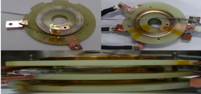
3.2. Superconducting Coil
To prevent sudden increase of the fault current, HTS coil is required. HTS coil consists of the 3 pancake coils connected in parallel and each pancake coil is wound with BSCCO tape. The fabricated 3 pancake coils are stacked each other and the magnetic field generated by each coil is mutually linked. By doing this, total coil inductance can be maintained as the single coil inductance despite the 3 coils were connected in parallel. The inner radius of a pancake coil bobbin is 54 mm and the number of turns is 50. The total inductance of HTS coil is 0.1 mH. Fig. 4 shows the fabricated HTS coil.
4. EXPERIMENTS AND ANALYSIS To verify the feasibility of the FCC system, short circuit tests with respect to the phase angle are performed. Test circuit diagram is presented in Fig. 5. When a fault occurs, fault switch (SW) is closed and load is separated from the AC Power Supply (P/S). Therefore, large current is applied to the FCC.
Note again that the purpose of the FCC is to maintain the fault current at proper level under the dynamic operating conditions where the fault current level changes. Thus, we perform the short circuit tests by varying the line resistance.
Table 2 shows the specifications of the short circuit tests.
To verify the FCC system, proper phase angle of the thyrisor is pre-calculated through the Simulink simulation as presented in Fig. 6. Then, short circuit test of the FCC is conducted by using the calculated phase angles obtained through the simulation. Simulation results demonstrate the
Fig. 4. Schematics of the fabricated HTS coil.
Fig. 5. Circuit diagram of the FCC short circuit test.
Fig. 6. Simulation model of the FCC.
Fig. 7. Calculated peak current data at 6-cycle after fault through simulation.
TABLE 2
S
PECIFICATION OF SHORT CIRCUIT TEST.
Specification Value
Input Voltage 30 V
peak,60 Hz Line resistance 0.25 Ω, 0.5 Ω
Load resistance 5Ω
Phase angle 0°, 60°, 100°, 115°, 130°, 145°, 160°, 180°
functional feasibility of the FCC. Fig. 7 shows the calculated peak current at 6-cycle after the fault with respect to the phase angle. To reduce the fault current to 25 A, phase angle of the FCC should be 130° and 145° for the line resistance of 0.5 Ω and 0.25 Ω, respectively. Based on the simulation results, short circuit experiments are carried out. Fig. 8 provides the fault current waveform at 0.5 Ω with respect to the phase angle.
14
Jae Young Jang, Woo Seung Lee, Jiho Lee, Young Jin Hwang, Hyun Chul Jo, Min Cheol Ahn, Kyeon Hur, and Tae Kuk Ko
(a) (b)
(c) (d)
Fig. 8. Fault current waveform when phase angle is (a) 0°, (b) 60°, (c) 115°, (d) 160°.
3.86 3.88 3.90 3.92 3.94 3.96 3.98 4.00 4.02 -40
-20 0 20 40 60 80 100
Cu rre nt [A ]
Time [s]
Line Current
(a)
3.24 3.26 3.28 3.30 3.32 3.34 3.36 3.38 3.40 -40
-20 0 20 40 60 80 100
Cu rre n [A ]
Time [s]
Line Current
(b)
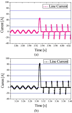
Fig. 9. Fault current waveform of (a) 130° at 0.5 Ω, (b) 145° at 0.25 Ω.
As clarified in Fig. 9, fault current converges to 25 A for those two cases (130° at 0.5 Ω, 145° at 0.25 Ω).
The whole graph which shows relation between the peak current and phase angle through both simulation and experiment is shown at Fig. 10. From Fig.10, similarity between the simulation result and experiment result was confirmed.
From Fig. 8, it is verified that the current waveform is more distorted and reduced as phase angle increase.
Fig. 10. Relation between peak current and phase angle through both simulations and experiments.
However, first peak fault current is not limited because of detecting time of the control circuit. Fig. 9 shows that both current waveform at 6-cycle after fault of two cases converge to 25 A, though first peak current of two cases are different.
This means that fault current can be reduced to the target value under the different conditions and experimental results are almost same with the simulation results.
Through these results, we can verify the controllability and feasibility of the FCC system.
5. CONCLUSION
As a new method of dealing with fault currents, FCC employing the superconducting coil was proposed. FCC control the fault current by adjusting the phase angle of the thyristor. From the simulation and experimental results performed by us, we can verify that the fault current is reduced to the target value according to the phase angle calculated by simulink simulation.
For the practical use of FCC system, it is needed to develop the auto controller which monitors all parts of the power grid and predicts the fault current and proper phase angle of the FCC to control the fault current. We confirmed the feasibility of proposed FCC system in this paper.
ACKNOWLEDGMENT
This work was supported by the National Research Foundation of Korea (NRF) grant funded by the Korea government (MEST) (No. 2011-0020401).
REFERENCES
[1] M. C. Ahn, T. K. Ko, “Proof-of-concept of a Smart Fault Controller with a Superconducting coil for the Smart Grid,” IEEE Trans. Appl.
Supercond., vol. 21, no. 3, pp. 2201-2204, Jun. 2011.
[2] M. C. Ahn, H. Kang, D. K. Bae, D. K. Park, Y. S. Yoon, S. J. Lee, and T. K. Ko,.”The Short-Circuit Characteristics of a DC reactor Type Superconducting Fault Current Limiter with Fault Detection and Signal Control of the Power Converter,” IEEE Trans. Appl.
Supercond., vol. 15, no. 2, pp. 2102-2105, Jun. 2005.